

Rockwell Automation FERROGARD GD2 Magnetically Actuated Interlock Switch User Manual [en, de, fr]
Page 1
2 3
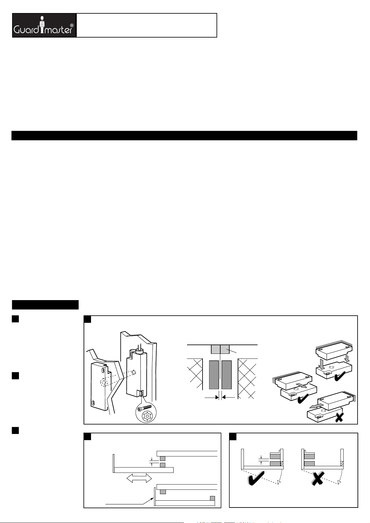
1
(d) No access to switch
thus preventing attempts
to defeat the interlock
(a) Where possible mount on non-ferrous materials
otherwise operating distances may be affected.
Einbauanleitung
(c) Installation Instructions Notice d'installation
Deutsch /
Français
RETAIN THESE INSTRUCTIONS
Installation must be in accordance with the following steps and must be
carried out by suitably competent personnel.
Whilst the Ferrogard complies with the requirements of EN 1088 it may not be
suitable for certain types of machinery or environments. Where magnetic
materials are present or if it is foreseeable that Ferrogard operation by
magnets other than the supplied actuator is possible then the use of an
alternative Guardmaster switch is recommended. Alternatively, additional
measures may be taken to prevent the Ferrogard being easily bypassed.
Consideration should be given to the recommended installation example given
in these instructions and those in EN 1088.
This device is intended to be part of the safety related control system of a
machine. Before installation, a risk assessment should be performed to
determine whether the specifications of this device are suitable for all
foreseeable operational and environmental characteristics of the machine to
which it is to be fitted.
At regular intervals during the life of the machine check whether the
characteristics foreseen remain valid and inspect this device for evidence of
accelerated wear, material degradation or tampering. If necessary the device
should be replaced . Guardmaster cannot accept responsibility for a failure of
this device if the procedures given in this sheet are not implemented or if it is
used outside the recommended specifications in this sheet.
The interlock switch is not to be used as a mechanical stop.
Guard stops and guides must be fitted.
Exposure to shock and/or vibration in excess of those stated in
IEC 68 part: 2-6/7 should be prevented.
Adherence to the recommended inspection and maintenance instructions
forms part of the warranty.
DIESE ANLEITUNG AUFBEWAHREN
Die Installation muß unter Einhaltung der nachstehend beschriebenen Schritte,
und durch geeignetes, fachlich qualifiertes Personal erfolgen.
Während Ferroguard den Anforderungen nach EN 1088 entspricht, ist diese
Vorrichtung eventuell nicht für gewisse Maschinentypen oder Umfelder
geeignet. Bei vorhandenen ferromagnetischen Materialien, oder bei einer
vorhersehbaren möglichen Funktion des Ferroguard mit Hilfe anderer
Magnete als dem mitgelieferten Betätiger, wird die Verwendung eines
alternativen Guardmaster-Schaltelementes empfohlen. Es können ferner
andere Maßnahmen ergriffen werden, die eine evtl. mögliche Umgehung des
Ferroguard verhindern. In diesem Sinne sollte das in dieser Anleitung
empfohlene Installationsbeispiel sowie die entsprechenden Vorgaben in EN
1088 berücksichtigt werden.
Diese Vorrichtung ist als Teil des sicherheitsrelevanten Kontrollsystems einer
Maschine beabsichtigt. Vor der Installation sollte eine Risikobewertung zur
Festlegung dessen erfolgen, ob die Spezifikationen dieser Vorrichtung für alle
vorhersehbaren betrieblichen und umweltbezogenen Eigenschaften der
jeweiligen Maschine geeignet sind, an der sie installiert werden soll.
Zu regelmäßigen Abständen während der Lebensdauer der Maschine ist zu
überprüfen, ob die vorhergesehenen Eigenschaften weiterhin gültig sind, und ob
Anzeichen von vorzeitigem Verschleiß, Materialermüdung oder unbefugten
Eingriffen erkennbar sind. Falls erforderlich, sollte die Vorrichtung ausgetauscht
werden. Guardmaster kann keinerlei Verantwortung für ein Versagen dieser
Vorrichtung übernehmen, wenn die in diesem Datenblatt gegebenen
Verfahrensweisen nicht implementiert wurden, oder wenn sie außerhalb der auf
diesem Schriftblatt empfohlenen Spezifikationen verwendet wird.
Der Magnet-Schalter darf nicht als mechanische Arretierung benutzt werden.
Schutztürarretierungen und Führungen sind anzubringen .
Eine Aussetzung an Stoßbelastungen und/oder Vibrationen, die überhalb den
in IEC 68, Teil 2-6/7 angegebenen Werten liegen, sollte verhindert werden.
Die Einhaltung der empfohlenen Inspektions- und Wartungsvorschriften formt
Teil der Garantie.
GARDEZ EN MÉMOIRE CES INSTRUCTIONS :
L’installation devra suivre les étapes suivantes et sera effectuée par du
personnel compétent et qualifié.
Bien que le Ferrogard soit conforme à la EN 1088, il n’est pas adapté à
certains environnements. Lorsque des matériaux magnétiques sont présents
ou lorsque la fraude du Ferrogard par un autre aimant est possible, il est alors
recommandé d’utiliser un autre interrupteur Guardmaster. En outre, des
mesures complémentaires peuvent être appliqué pour éviter la fraude facile
du Ferrogard. On examinera les exemples présentés dans la notice d’une part,
et ceux décrits dans la norme 1088 d’autre part.
Ce système est conçu pour être implanté dans la partie sécurité du système de
commande d’une machine. Avant l’installation, il faut effectuer une
appréciation des risques pour vérifier que les caractéristiques de cet appareil
sont appropriées aux critères d’utilisation et d’environnement de la machine.
Pendant toute la vie de la machine, en respectant des périodes de vérifications
régulières, Assurez-vous que l’appareil conserve ses performances, inspectez
le montage du dispositif pour déceler les traces éventuelles d’usure, de
dégradation ou de fraudes. Si nécessaire, remplacez l’appareil. Guardmaster
n’accepte pas la responsabilité d’une panne de cet appareil si les procédures
décrites dans la présente notice n’ont pas été respectées ou si l’appareil est
utilisé en dehors des recommandations décrites.
Cet interverrouillage ne doit pas servir de butée mécanique d’arrêt.
La porte doit être équipée de guides et de butées mécaniques.
Evitez d’exposer l’appareil à des chocs et/ou des vibrations supérieurs à ceux
définis dans la norme CEI 68 part. 1-6/7.
Le respect des périodes de vérifications régulières, des instructions relatives au
contrôle et à l’entretien font parties intégrantes de la garantie.
2mm
(b) Door closed
(e) Door open covering switch
(b) If required by a risk assessment, reduce the possibility of the switch being
defeated by preventing access to the switch when the guard door is open.
SLIDING DOOR
(a)
SLIDING GUARDS/SCHIEBBARE SCHUTZTÜREN/
PANNEAUX DE PROTECTION
(a)
HINGED GUARDS
Mount switch at opening edge of guard door
SLIDING DOOR
2mm
FERROGARD GD2
MAGNETICALLY ACTUATED INTERLOCK SWITCH
BERÜHRUNGSLOSER MAGNET-SCHALTER
INTERRUPTEUR DE SÉCURITÉ MAGNÉTIQUE INOX SANS CONTACT
(b) Description
The Ferrogard GD2 range of magnetically actuated, non-contact
safety interlock switches are used to stop machine power when a
guard is opened. When the stop signal is applied and the guard is
opened, the action of the actuator being removed from the switch
isolates the machine contactor control power. If redundancy and
monitoring is required, the Guardmaster Minotaur range of
monitoring units should be considered.
Note: All Ferrogards have internal non-resettable overload protection.
They should be protected by an external fuse rated as shown at
step 6.
Beschreibung
Die magnetisch betätigten, berührungslosen Magnet-Schalter der
Typenreihe Ferroguard GD2 werden zur Trennung der
Stromversorgung an eine Maschine bei Öffnung einer Schutztür
verwendet. Wenn das Stopsignal ausgelöst, und die Schutztür
geöffnet wird, wird der Betätiger durch die Türbewegung vom Schalter
entfernt, und dadurch die Steuerstromzufuhr zum Schaltschütz der
Maschine getrennt. Für evtl. gewünschte Redundanz- und
Überwachungsfunktionen sollten die Überwachungsschalter der
Typenreihe Guardmaster Minotaur in Betracht gezogen werden.
Anmerkung: Alle Ferroguard-Schaltelemente haben einen internen,
nicht-rückstellbaren Überlastungsschutz, und sollten deshalb durch
eine externe Sicherung mit den unter Schritt 6 angegebenen
Nennwerten geschützt werden.
Description
Le « Ferrogard GD2 » est un capteur magnétique de sécurité sans
contact pour porte de machine en acier inoxydable. Il coupe
l’alimentation électrique dès que celle-ci est ouverte. Quand la porte
est ouverte, le bloc contact du Ferrogard, séparé de son aimant, ouvre
le circuit du contacteur de puissance. Si un circuit redondant et autocontrôlé est nécessaire, il suffit de connecter les appareils de la
gamme Ferroguard avec ceux de la famille des blocs logiques
Minotaur ( voir Guardmaster pour le choix des appareils ).
NOTE : Chaque Ferroguard est équipé d’une protection contre les
surcharges. Cette protection assure la sécurité de l’opérateur par
destruction d’un composant non remplaçable. Il doit donc être protégé
par un fusible externe dont le calibre est défini au paragraphe 6.
Operation: target face to target face
Einbauposition: Kontaktflächen gegenüberliegend
Utilisation: face cible contre face cible
Guard Stops
Recommended gap between sensor and actuator.
Empfohlener Abstand zwischen Sensor und Betätiger.
Ecart préconisé entre le récepteur et l’émetteur.
NOTE: ACTUATOR MUST NOT STRIKE SENSOR
ANMERKUNG: DER BETÄTIGER DARF DEN SENSOR
NICHT BERÜHREN
REMARQUE: L’ÉMETTEUR NE DOIT PAS HEURTER LE RÉCEPTEUR
2mm
(a)
1
(b)
(d)
(e)
(c)
(a) Nach Möglichkeit nur auf nicht-
ferritischen Materialien montieren, um
eine Beeinflussung der
Funktionsabstände zu vermeiden /
Si possible, installer le Ferrogard sur
des supports non magnétiques, afin de
ne pas diminuer les distances de détection
(c) Schutztürarretierungen /
Butées du panneau de protection
2
(b) Tür geschlossen /
Porte fermée
(c) SCHIEBETÜR /
Porte coulissante
(d) Kein Zugang zum Schalter, dadurch
keine Umgehungsmöglichkeit der
Sicherheitsverriegelung /
Pas de possibilité d'accéder à l’appareil
pour le frauder
(e) Tür geöffnet, kein Zugang zum Schalter
/
Porte ouverte couvrant l’interrupteur
(c)
3
(a) SCHWENKBARE SCHUTZTÜREN
Schaltermontage an der Öffnungsseite
der Schutztür /
PORTES OU PROTECTEURS À CHARNIÈRES
Monter l’interrupteur sur le bord ouvrant
de la porte de protection
(b) Falls während der Risikobewertung
entsprechend festgestellt, muß eine
mögliche Umgehung des Schalters
durch Zugangsverwehrung bei
geöffneter Schutztür verhindert werden
/
Si cela est imposé lors de l'appréciation
du risque, limiter la neutralisation
de l’interrupteur lors de l’ouverture
du protecteur
Page 2
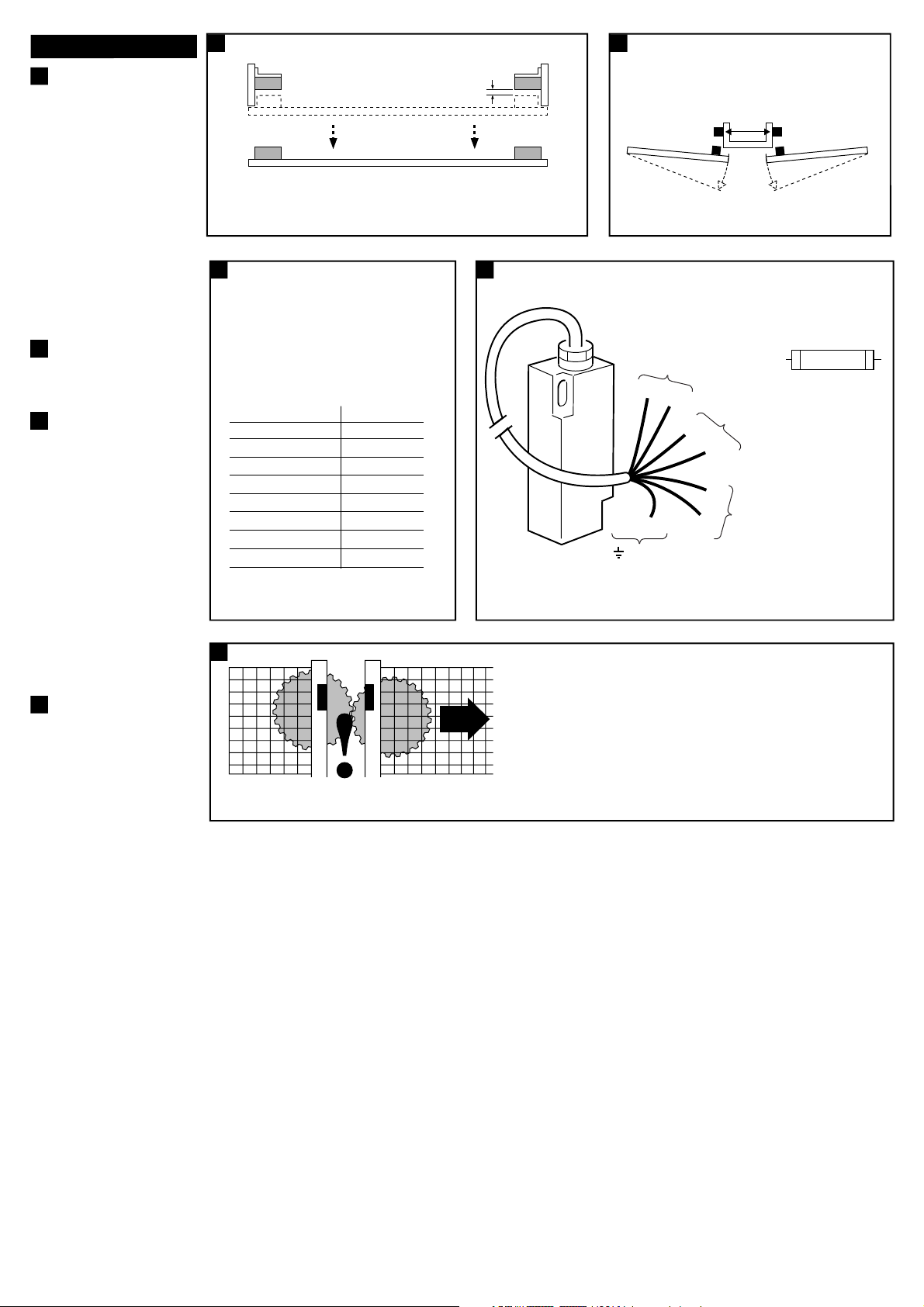
4 5
6
(a) GD2 external fuse rating
(safety contacts) /
Sicherungs-Nennwerte für GD2
(Schutzkontakte) /
Curant nominal du fusible GD2
(contacts de sécurité)
7
(a) CONNECTION / ELEKTRISCHE ANSCHLÜSSE / CONNEXION
Deutsch /
Français
(b) If required by a risk assessment, reduce the possibility of the switch being
defeated by preventing access to the switch when the guard door is open.
(c) Ensure that the switch can not be actuated unless the guard is in its intended position.
(a)
LIFT OFF GUARDS
2mm
≥ 50mm
(c) Actuator
Actuator
Switch
(b) Switch
Important / Wichtig / Important
(b) Ferrogard GD2 type Fuse type
1AC ≤ 1.6A quick blow
1DC ≤ 800mA quick blow
2AC ≤ 1.6A quick blow
2DC ≤ 800mA quick blow
20AC ≤ 1.6A quick blow
20DC ≤ 800mA quick blow
21AC ≤ 1.6A quick blow
21DC ≤ 800mA quick blow
(n) Quick Blow
(o) Fuse each safety
circuit externally (see 6)
AUXILIARY (types 2, 21)
EARTH (types 1, 2, 20, 21)
GREEN
YELLOW
YELLOW/GREEN
IMPORTANT
WICHTIG
IMPORTANT
8
After installation check all of the interlocked doors to ensure that
the machine is isolated and stopped whenever the guard is not closed.
Nach erfolgter Montage an allen abgesicherten Türen prüfen, ob die
Stromversorgung zur Maschine getrennt, und die Maschine abgeschaltet wird, wenn
die Schutztür nicht geschlossen ist.
Après installation, manoeuvrez chaque porte pour vous assurer de
l'arrêt de la machine tant que chaque protecteur n'est pas fermé.
BOND ALL UNUSED WIRES TO EARTH / ALLE UNBELEGTEN KABEL ERDEN /
METTRE TOUS LES FILS INUTILISÉS A LA TERRE
BLACK
SAFETY 1 (types 1, 2, 20, 21)
SAFETY 2 (types 20, 21)
WHITE
RED
BLUE
4
(a) ABNEHMBARE SCHUTZABDECKUNGEN
/
PORTES OU PROTECTEURS AMOVIBLES
(b) Falls während der Risikobewertung
entsprechend festgestellt, muß eine
mögliche Umgehung des Schalters
durch Zugangsverwehrung bei
entfernter Schutzabdeckung verhindert
werden /
Si cela est imposé lors de
l'appréciation du risque, limiter la
neutralisation de l’interrupteur lors de
l’ouverture du protecteur
(c) Sicherstellen, daß der Schalter nur
dann betätigt werden kann, wenn die
Abdeckung angebracht ist /
S'assurer
que les conatcts ne peuvent pas être
activés tant que le protecteur n'est pas
dans sa position définitive
5
(b) Schalter /
Interrupteur
(c) Betätiger /
Emetteur
(a)
6
(b) Ferrogard Typ GD2 Sicherungstp
1 AC ≤ 1,6 A Flinksicherung
1 DC ≤ 800 mA Flinksicherung
2 AC ≤ 1,6 A Flinksicherung
2 DC ≤ 800 mA Flinksicherung
20 AC ≤ 1,6 A Flinksicherung
20 DC ≤ 800 mA Flinksicherung
21 AC ≤ 1,6 A Flinksicherung
21 DC ≤ 800 mA Flinksicherung
/
Type Ferrogard GD2 Type de fusible
1 c. alternatif ≤Fusible instantané = 1,6A
1 c. continu≤Fusible instantané = 800mA
2 c. alternatif≤Fusible instantané = 1,6A
2 c. continu≤Fusible instantané = 800mA
20 c. alternatif≤Fusible instantané = 1,6A
20 c. continu≤Fusible instantané = 800mA
21 c. alternatif≤Fusible instantané = 1,6A
21 c. continu≤Fusible instantané = 800mA
(b)
(c)
(i)
(j)
(h)
(g)
(f)
(e)
(d)
(k)
(m)
(l)
7
(c) SCHUTZSCHALTUNG 1
(Sicherungstyp 1, 2, 20, 21) /
Sécurité (types 1, 2, 20, 21)
(d) ROT /
ROUGE
(e) BLAU /
BLEU
(f) SCHWARZ /
NOIR
(g) WEISS /
BLANC
(h) GRÜN /
VERT
(i) GELB/GRÜN /
JAUNE/VERT
(j) GELB /
JAUNE
(k) ERDE (Sicherungstypen 1, 2, 20, 21) /
Terre (types 1, 2, 20, 21)
(m) HILFSKONTAKTE (Typen 2, 21) /
AUXILIAIRES (TYPES 2, 21)
(n) Flinksicherung /
Déclenchement
instantané
(o) Jeden Schutzschaltkreis extern sichern
(siehe 6) /
Munir chaque circuit de
sécurité d’un fusible extérieur (voir 6)
(a)
Page 3

Conforming to standards EN1088, EN292, EN60204-1
Safety contact arrangement
Types 1AC, 2AC , for AC circuits only 1N/C special safety reed - 250VAC 2A max
(fuse externally 1.6A quick blow)
Types 20AC, 21AC, for AC circuits only 2N/C special safety reed - 250VAC 2A max
(fuse externally 1.6A quick blow)
Types 1DC, 2DC, for DC circuits only
1N/C special safety reed - 24V DC 1amp max
(fuse externally 800mA quick blow)
Types 20DC, 21DC, for DC circuits only
2N/C special safety reed - 24V DC 1amp max
(fuse externally 800mA quick blow)
Safety contact operating distance Make 12mm - Break 23mm
Auxiliary contact operating distance
Types
2 & 21 Break 10mm - Make 13mm
Reed contacts Safety Auxiliary
Closing time 3.0mS 0.5mS
Drop out time 2.1mS 0.3mS
Bounce time 0.7mS 0.7mS
Shock 50G 100G
Vibration 7-15G’s, 10 to 200Hz
Initial contact resistance 15mΩ 1OmΩ
Initial capacitance, terminals 0.65 pF 0.2pF
Initial insulation res. terminals 1 x 10
6
OHMS 1 x 10⁶ OHMS
Min. initial b/down voltage 600VAC RMS 600VAC RMS
Auxiliary contact arrangement
Types
2, 21 1N/O
300VDC, 250VAC (RMS) 0.5A INC.
INRUSH. 15VA/10W. for AC/DC circuits
Case material Stainless Steel BS3146 Pt 2 Anc 4BFC
Protection IP68
Operating temperature –25°C to 125°C
Fixing M4 tamper resistant
Mounting configuration Any position
Mechanical life 10 x 10
6
Electrical life 1 x 10
6
Colour Silver
Cleaning May be high pressure steam cleaned
Cable Stranded 7 core. Flexible thermoplastic
elastomer sheathed 7/0.5mm
NOTE: The safety contacts of the Guardmaster switches are described as
normally closed (N/C) i.e. with the guard closed, actuator in place and the
machine able to be started.
(d) Technical Specifications
16
11.50
8
7
19.5
7
7
7
4.4
39.2539.25
78.5
16.75
16.75
16.75 16.75
33.5
62.5
11.5
5
62.5
19.5
33.5
78.50
4.4
8
6
(a) SWITCH
16
5
(b) ACTUATOR
9
39.2539.25
8
7
Normative Auslegung entsprechend: EN 1088, EN 292, EN 60204-1
Schutzkontaktanordnung
Typen 1AC, 2AC - nur für AC-Schaltkreise 1 Spezial-Reed-Schutzkontakt -
250 V AC, 2 A max (Ruhekontakt).
(Mit externer Flinksicherung 1,6 A sichern)
Typen 20 AC, 21 AC - nur für 2 Spezial-Reed-Schutzkontakte AC-Schaltkreise 250 V AC, 2 A max (Ruhekontakte).
(Mit externer Flinksicherung 1,6 A sichern)
Typen 1 DC, 2DC - nur für DC-Schaltkreise 1 Spezial-Reed-Schutzkontakt -
24 V DC, 1 A max (Ruhekontakt).
(Mit externer Flinksicherung 800 mA sichern)
Typen 20 DC, 21 DC - nur für 2 Spezial-Reed-Schutzkontakte DC-Schaltkreise 24 V DC, 1 A max (Ruhekontakt).
(Mit externer Flinksicherung 800 mA sichern).
Schutzkontakt-Funktionsdistanz EIN = 12 mm, AUS = 23 mm
Hilfskontakt-Funktionsdistanz
Typen 2 und 21 AUS = 10 mm, EIN = 13 mm
Reed-Kontakte Schutzkontakt Hilfskontakt
Schließzeit 3,0 ms 0,5 ms
Abfallverzögerung 2,1 ms 0,3 ms
Prellzeit 0,7 ms 0,7 ms
Stoß 50 G 100 G
Vibration 7 - 15 G, 10 - 200 Hz
Anfängl. Kontaktwiderstand 15 mΩ 10 mΩ
Anfängl. Kapazität, Klemmen 0,65 pF 0,2 pF
Anfängl. Isolierwiderstand, Klemmen 1 x 10 Ω 1 x 10 Ω
Min. anfängl. Durchschlagsspannung 600 V AC eff. 600 V AC eff.
Hilfskontakt-Auslegung
Typen 2, 21 1 Schließkontakt
300 V DC, 250 V AC (eff.), 0,5 A INKL.
EINSCHALTSTROM, 15 VA/10 W für
AC/DC-Schaltkreise
Gehäusematerial Rostfreier Stahl BS 3146 Teil 2 Anc 4 BFC
Schutzklasse IP 68
Betriebstemperatur -25°C bis 125°C
Montage M4, eingriffsicher
Montageanordnung In beliebiger Position
Mechanische Lebendauer 10 x 10
Elektrische Lebensdauer 1 x 10
Farbgebung Silber
Reinigung Kann mit Hochdruckdampf erfolgen
Kabel Verseilt, 7-adrig. Abschirmung
Thermoplastik-Elastomer 7/0,5 mm
ANMERKUNG: Die Schutzkontakte der Guardmaster-Schalter werden als
Ruhekontakte beschrieben, d.h. bei geschlossener Schutztür, Betätiger in
Position, und startbereiter Maschine.
Technische Daten
Conforme aux normes suivantes EN 1088, EN 292, EN 60204-1
Disposition des contacts de sécurité
Types 1 c. alternatif, 2 c. alternatif 1 commutateur à lames spécial N/F pour circuits c. alternatif seulement 250 V c. alternatif 2A maximal
(fusible externe : 1,6A instantané)
Types 20 c. alternatif, 21 c. alternatif 2 commutateurs à lames spécial N/F pour circuits c. alternatif seulement 250 V c. alternatif 2A maximal
(fusible externe : 1,6A instantané)
Types 1 c. continu, 2 c. continu 1 commutateur à lames spécial N/F pour circuits c. continu seulement Voyant 24 V c. continu 2A maximal
(fusible externe : 800mA instantané)
Types 20 c. continu, 21 c. continu 2 commutateurs à lames spécial N/F pour circuits c. continu seulement Voyant 24 V c. continu 2A maximal
(fusible externe : 800mA instantané)
Distance de service du contact de Contact : 12 mm
sécurité Coupure : 23 mm
Distance de service du contact auxiliaire
Types 2 et 21 Contact : 10 mm Coupure : 13 mm
Contacts des lames Sécurité Auxiliaire
Temps de fermeture 3,0 ms 0,5 ms
Temps de désexcitation 2,1 ms 0,3 ms
Temps de saut 0,7 ms 0,7 ms
Décharge 50 G 100 G
Vibration 7 - 15 G, 10 - 200 Hz
Résistance de contact initiale 15 mΩ 10 mΩ
Capacité initiale, bornes 0,65 pF 0,2 pF
Isolation initiale, bornes rés. 1 x 10 Ω 1 x 10 Ω
Tension minimum initiale de 600V c. alternatif efficace
coupure
Disposition des contacts auxiliaires
types 2, 21 1 N/O
300V c. continu, 250V c. alternatif
(efficace) 0,5A inc. d’entrée,
15VA/10W pour circuits DC
Matériau du boîtier Inox BS3146 Pt 1 Anc 4BFC
Protection IP68
Température de service -25°C à 125°C
Fixation M4 infraudable
Configuration de montage Toutes positions
Durée de vie mécanique 10 x 10
Durée de vie électrique 1 x 10
Couleur Argent
Nettoyage Peut être nettoyé à la vapeur haute
pression
Câble Toronné 7 conducteurs, gaine
élastomère thermoplastique souple
7/0,5 mm
REMARQUE : les contacts de sécurité des interrupteurs Guardmaster sont
décrits comme étant normalement fermés (N/F) ; autrement dit, avec porte
de protection fermée, émetteur en place et machine en mesure de démarrer.
Spécifications Techniques
9
(a) SCHALTER /
Récepteur
(b) BETÄTIGER /
Emetteur
6
6
6 6
6 6
6
6
Page 4

Security screwdriver
Replacement security key
Replacement actuators are available by arrangement.
Note: Access to spare actuators should be restricted to
authorised personnel to prevent bypassing of the safety function
Sicherheits-Schraubendreher
Sicherheits-Ersatzschlüssel
Austauschbetätiger sind nach Vereinbarung lieferbar.
Anmerkung: Der Zugang zu Austauschbetätigern sollte auf autorisierte
Personen beschränkt werden, um Umgehungen der Schutzfunktion zu
verhindern.
Tournevis de sécurité
Clé de sécurité de rechange
Aimants de rechange disponibles.
Note : l’accès aux aimants de rechange doit être strictement réduit
au personnel autorisé pour éviter la fraude de la fonction de sécurité
.
ZUBEHÖR
(e) ACCESSORIES ACCESSOIRES
WARTUNG
(f) MAINTENANCE ENTRETIEN
Every Week
Inspect the switch casing & actuator for damage or distortion. Check
for correct alignment, see step 1. Replace or adjust where necessary.
Also check operation of the switching circuit.
Chaque semaine :
Inspecter le boîtier et l’aimant pour détecter les dommages et
vérifier les alignements (voir étape 1). Remplacer ou ajuster si
nécessaire. Tester le bon fonctionnement du circuit.
Wöchentlich
Schaltergehäuse und Betätiger auf Beschädigung oder Verziehung
überprüfen. Korrekte Ausrichtung prüfen, siehe Schritt 1. Falls
erforderlich, austauschen oder neu justieren. Ebenso die Funktion des
Schaltkreises überprüfen.
REPARATUR
(g) REPAIR RÉPARATIONS
If there is any malfunction or damage, no attempts should be made
to repair it. The switch should be replaced before machine operation
is allowed.
DO NOT DISMANTLE THE UNIT.
En cas de dysfonctionnement ou de dégradation, ne pas attendre
pour réparer. L'interrupteur doit être remplacé immédiatement avant
le démarrage de la machine.
DANS TOUS LES CAS, NE DISLOQUEZ PAS L'APPAREIL.
Falls Fehlfunktionen oder Schäden auftreten, keine Versuche zur
Reparatur unternehmen. Der Schalter muß ersetzt werden, bevor die
Maschine wieder gestartet wird.
GERÄT DARF NIEMALS GEÖFFNEN WERDEN!
(h) TROUBLESHOOTING
Symptom
Safety circuit fails to close
Auxiliary circuit fails to open
Safety circuit fails to open
Cause
Actuator misaligned
External fuse blown
Internal fuse blown (incorrect installation)
Actuator misaligned
External wiring fault
Remedy
Adjust alignment
Determine cause of overcurrent & remedy
Replace switch - fit external fuse.
Install as steps 1 & 2
Determine cause of fault & remedy. If the
fault is foreseeable, consider the use of dual
channel techniques with a Guardmaster
Minotaur monitoring safety relay.
Drg No: 37613 / Issue No: 0
Symptom
Öffnerkreis schließt nicht
Hilfskontaktkreis schließt nicht
Öffnerkreis öffnet nicht
Ursache
Betätiger verschoben
Externe Sicherung angesprochen
Interne Sicherung angesprochen
(nicht korrekt angeschlossen)
Betätiger verschoben
Fehler in der externen Verdrahtung
Beseitigung
In Linie montieren
Ursache feststellen und beseitigen
Schalter ersetzen - Externe Sicherung
montieren
Nach Schritt 1 und 2 montieren
Fehler voraussehbar ist, den Einsatz von 2kanaligen Techniken mit einem RelaisSicherheitsbaustein von GUARDMASTER
erwägen.
FEHLERSUCHE
Symptôme
Le circuit de sécurité ne se ferme pas
Le circuit auxiliaire ne s’ouvre pas
Le circuit de sécurité ne s’ouvre pas
Cause
L’émetteur n’est pas aligné
Le fusible externe a sauté
Le fusible interne a sauté (mauvaise installation)
Emetteur non aligné
Défaut de câblage interne
Solution
Ajuster l’alignement
Déterminer la cause de la surintensité et
rectifier
Remplacer l’interrupteur - Monter un
fusible externe
Installer conformément aux points 1 et 2
Déterminer la cause et rectifier. Si ce
défaut était imprévisible, envisager
l’utilisation de techniques à deux canaux
avec un relais de sécurité de contrôle
Guardmaster Minotaur.
DÉPISTAGE DES DÉFAUTS
R
 Loading...