

Page 1

Installation
Manual
FD86N
Drive Systems
Enclosure
Hardware
Page 2

Important User
Information
The illustratio ns shown in thi s guide are intended sole ly for purposes of e xample. Since
there are many variables and requirements associated with any particular installation,
Rockwell Automation Drive Systems does not assume responsibility or liability (to
include intell ectual prope rty liabil ity) for a ctual use ba sed upon th e examples show n in
this publication.
Reproduction of the contents of this copyrigh ted publication, in whole or i n part, without
written permission of Rockwell Automation is prohibited.
Throughout this manual we use notes to make you aware of safety considerations:
ATTENTION:
that can lead to pe rs ona l injury or death, prope rt y damage, or economic
!
Attention statements help you:
identify a hazard
•
avoid the hazard
•
recognize the consequenc es
•
Important: Identifies information that is critical for successful application and
CENTERLINE
Torx is a trademark of Text ron Inc.
loss.
understanding of the product.
is a trademark of Rockwell International or its subsidiaries.
Identifies i nformation about pr actices or circ umstances
Page 3

Publication S-3062 – November 1997
Table of Contents
Preface
Who Should Use this Manual
. . . . . . . . . . . . . . . . . . . . . . . . . . . . . .
P-1
Purpose of this Manual
. . . . . . . . . . . . . . . . . . . . . . . . . . . . . . . . . . .
P-1
Safety Precautions
. . . . . . . . . . . . . . . . . . . . . . . . . . . . . . . . . . . . . .
P-1
How to Use this Manual
. . . . . . . . . . . . . . . . . . . . . . . . . . . . . . . . . .
P-2
Contents of this Manual
. . . . . . . . . . . . . . . . . . . . . . . . . . . . . . . . . .
P-2
Related Documentation
. . . . . . . . . . . . . . . . . . . . . . . . . . . . . . . . . .
P-3
Conventions Used in this Manual
. . . . . . . . . . . . . . . . . . . . . . . . . . .
P-3
Drive Systems Receiving
. . . . . . . . . . . . . . . . . . . . . . . . . . . . . . . . .
P-3
Rockwell Automation Drive Systems Support
. . . . . . . . . . . . . . . . . .
P-4
Local Product Support
. . . . . . . . . . . . . . . . . . . . . . . . . . . . . . . . .
P-4
Technical Product Assistance
. . . . . . . . . . . . . . . . . . . . . . . . . . .
P-4
Chapter 1
Overview of the FD86N
Enclosure
Introduction
. . . . . . . . . . . . . . . . . . . . . . . . . . . . . . . . . . . . . . . . . . . .
1-1
What is the FD86N Enclosure?
. . . . . . . . . . . . . . . . . . . . . . . . . . . . .
1-1
Standard Features of the FD86N Enclosure
. . . . . . . . . . . . . . . . . . .
1-1
Standard Options of the FD86N Enclosure
. . . . . . . . . . . . . . . . . . . .
1-2
Bulletin 2300 MCC Compatibility
. . . . . . . . . . . . . . . . . . . . . . . . . . .
1-2
Chapter 2
Installing the FD86N Enclosure
Introduction
. . . . . . . . . . . . . . . . . . . . . . . . . . . . . . . . . . . . . . . . . . . .
2-1
Before You Begin
. . . . . . . . . . . . . . . . . . . . . . . . . . . . . . . . . . . . . . .
2-1
Unpackin g the Enclosure
. . . . . . . . . . . . . . . . . . . . . . . . . . . . . . . . .
2-1
Handling the Enclosure
. . . . . . . . . . . . . . . . . . . . . . . . . . . . . . . . . . .
2-1
Storing the Enclosure
. . . . . . . . . . . . . . . . . . . . . . . . . . . . . . . . . . . .
2-1
Site Planning
. . . . . . . . . . . . . . . . . . . . . . . . . . . . . . . . . . . . . . . . . . .
2-2
Space Requirements
. . . . . . . . . . . . . . . . . . . . . . . . . . . . . . . . . .
2-2
Support Requirements
. . . . . . . . . . . . . . . . . . . . . . . . . . . . . . . .
2-2
Entry and Exit Provisions for Wiring
. . . . . . . . . . . . . . . . . . . . . .
2-2
Lifting the Enclosure
. . . . . . . . . . . . . . . . . . . . . . . . . . . . . . . . . . . . .
2-3
Anchoring and Mounting the Enclosure
. . . . . . . . . . . . . . . . . . . . . .
2-5
Joining Control Enclosure Sections
. . . . . . . . . . . . . . . . . . . . . . . . .
2-5
Joining Control Enclosures to Bulletin 2100 MCCs
. . . . . . . . . . . . .
2-6
Protecting Ventilated Control Enclosure Equipm ent
During Installation
. . . . . . . . . . . . . . . . . . . . . . . . . . . . . . . . . . . . .
2-7
Removing Lifting Angles
. . . . . . . . . . . . . . . . . . . . . . . . . . . . . . . . . .
2-7
Installing Conduit
. . . . . . . . . . . . . . . . . . . . . . . . . . . . . . . . . . . . . . .
2-7
Installing a Typical Bus Bar Assembly
. . . . . . . . . . . . . . . . . . . . . . .
2-8
Installing a Pull Box to a Bus Bar Enclosure
. . . . . . . . . . . . . . . . . . .
2-9
Installing an Equipment Enclosure to the FD86N Enclosure
. . . . .
2-10
Installing an Air Conditioning Unit to the FD86N Enclosure
. . . . . .
2-11
Installing a Mechanical Door Interlock Link between
FD86N Enclosures
. . . . . . . . . . . . . . . . . . . . . . . . . . . . . . . . . . .
2-12
Page 4

toc–ii
Table of Contents
Publication S-3062 – November 1997
Chapter 3
Joining Bus Bar Assemblies
Introduction
. . . . . . . . . . . . . . . . . . . . . . . . . . . . . . . . . . . . . . . . . . . .
3-1
Before You Begin
. . . . . . . . . . . . . . . . . . . . . . . . . . . . . . . . . . . . . . . .
3-1
Splicing Single Bus Bar Assemblies
. . . . . . . . . . . . . . . . . . . . . . . . .
3-1
Splicing Parallel Bus Bar Assemblies
. . . . . . . . . . . . . . . . . . . . . . . .
3-2
Installing Bus Bar Tabs for Incoming Power
. . . . . . . . . . . . . . . . . . .
3-3
Making Connections to Drop Tabs
. . . . . . . . . . . . . . . . . . . . . . . . . . .
3-5
Joining Bus Bar Enclosures
. . . . . . . . . . . . . . . . . . . . . . . . . . . . . . . .
3-7
Installing DC Bus Bar Connections to a Bulletin2100 MCC
. . . . . . .
3-8
Installing DC Bus Bar Adapter Connections to an
SA3000 or SB3000
. . . . . . . . . . . . . . . . . . . . . . . . . . . . . . . . . . . .
3-9
Installing the Ground Cables between FD86N Enclosures
. . . . . . .
3-10
Connecting the Incoming Ground Bus
. . . . . . . . . . . . . . . . . . . . . . .
3-11
Chapter 4
Maintenance
Introduction
. . . . . . . . . . . . . . . . . . . . . . . . . . . . . . . . . . . . . . . . . . . .
4-1
Protecting Ventilated Control Enclosures Du ring Mai ntena nce
. . . . .
4-1
Cleaning the Filter
. . . . . . . . . . . . . . . . . . . . . . . . . . . . . . . . . . . . . . .
4-1
Replacing Cabinet Light Bulbs
. . . . . . . . . . . . . . . . . . . . . . . . . . . . . .
4-1
Page 5

Publication S-3062 – November 1997
Table of Illustratio ns
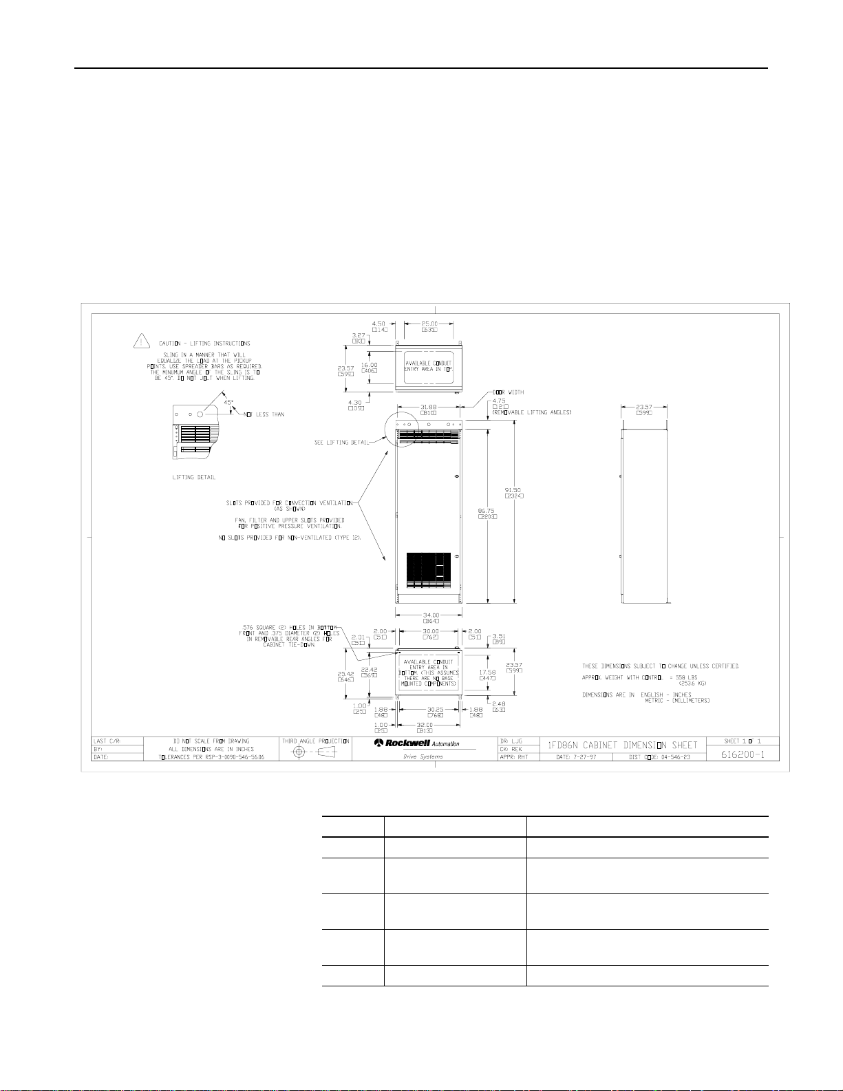
Figure P.1
Typical Dimension Sheet
. . . . . . . . . . . . . . . . . . . . . . . .
P-2
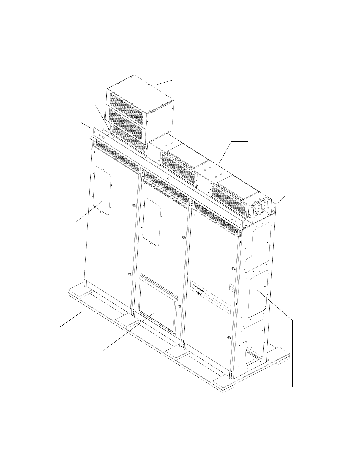
Figure 1.1
Typical 3FD86N Enclosure with Standard Options
. . . . .
1-3
Figure 2.1
Minimum Sling Angle Requirement
. . . . . . . . . . . . . . . . .
2-3
Figure 2.2
Typical Lifting (End View)
. . . . . . . . . . . . . . . . . . . . . . . .
2-4
Figure 2.3
Typical Lifting (Front Views)
. . . . . . . . . . . . . . . . . . . . . .
2-4
Figure 2.4
Joining Enclosure Sections (End Panel Outside Views)
.
2-5
Figure 2.5
FD86N Enclosure with End Plates for Connection
to a Bulletin 2100 MCC
. . . . . . . . . . . . . . . . . . . . . . . . . .
2-6
Figure 2.6
Installing a Bus Bar Assembly to an FD86N Enclosure
.
2-8
Figure 2.7
Installing a Pull Box to a Bus Bar Enclosure
. . . . . . . . . .
2-9
Figure 2.8
Installing an Equipment Enclosure to the
FD86N Enclosure
. . . . . . . . . . . . . . . . . . . . . . . . . . . . .
2-10
Figure 2.9
Installing an Air Conditioner to the Left or Right End of the
FD86N Enclosure
. . . . . . . . . . . . . . . . . . . . . . . . . . . . .
2-11
Figure 2.10
Installing a Mechanical Door Interlock Link between
FD86N Enclosures
. . . . . . . . . . . . . . . . . . . . . . . . . . . .
2-12
Figure 3.1
Splicing Single Bus Bar Assemblies
. . . . . . . . . . . . . . . .
3-1
Figure 3.2
Splicing Parallel Bus Bar Assemblies
. . . . . . . . . . . . . . .
3-2
Figure 3.3
Typical Installation of Incoming AC Bus Bar
Tabs (Staggered)
. . . . . . . . . . . . . . . . . . . . . . . . . . . . . .
3-3
Figure 3.4
Typical Installation of Incoming AC Bus Bar Tabs (Inline)
3-3
Figure 3.5
AC Bus Bar Tab Hardware Orientation
. . . . . . . . . . . . . .
3-4
Figure 3.6
Typical 4
Drop Tab Connections
. . . . . . . . . . . . . . . . . .
3-5
Figure 3.7
Typical 6
Drop Tab Connections
. . . . . . . . . . . . . . . . . .
3-6
Figure 3.8
Installing a Sheet Metal Joiner for Bus Bar Enclosures
(FD86N to FD86N)
. . . . . . . . . . . . . . . . . . . . . . . . . . . . .
3-7
″
″
Page 6

toi-ii
Table of Illustrations
Publication S-3062 – November 1997
Figure 3.9
Installing a Sheet Metal Joiner on an Overhead Cable
Routing Box (FD86N to SA3000 or SB3000)
. . . . . . . . . .
3-7
Figure 3.10
Installing DC Bus Bar Connections from the
FD86N Enclosure to an MCC
. . . . . . . . . . . . . . . . . . . . . .
3-8
Figure 3.11
Installing the DC Bus Bar Adapter Connections between an
SA3000 or SB3000 and a DC Bus Bar Assembly
on the FD86N Enclosure
. . . . . . . . . . . . . . . . . . . . . . . . .
3-9
Figure 3.12
FD86N Enclosure to FD86N Enclosure Ground Cable
Location and Hardware Orientation
. . . . . . . . . . . . . . . .
3-10
Figure 3.13
Connecting Incoming Ground Bus Bar Assembly Cables
to the FD86N Enclosure
. . . . . . . . . . . . . . . . . . . . . . . . .
3-11
Figure 3.14
Grounding Hardware Connections
. . . . . . . . . . . . . . . . .
3-12
Page 7

Publication S-3062 – November 1997
Preface
Preface
Please read this preface to familiarize yourself with the rest of this
Who Should Use this Manual
Purpose of this Manual
Safety Precautions
manual. This preface describes:
who should use this manual
•
the purpose of this manual
•
safety precautions
•
how to use this manual
•
contents of this manual
•
conventions used in this manual
•
drive system rece iving informatio n
•
how to contact Rockwell Automation support
•
Use this manual if you are responsible for installing or handling the
FD86N enclosure.
This manual provides installation instructions for the FD86N
enclosure, including instruction on:
unpacking, handling, lifting, and storage
•
site planning
•
installing equipment such as pull boxes and equipment enclosures
•
joining bus bar assemblies
•
maintaining the enclosure
•
These general precautions apply to the FD86N enclosure and its
respective drive systems.
ATTENTION:
system, the products used in the system, and the
!
associated machinery should plan or implement the
installation, startup, and maintenance of the system.
Failure to comply can result in personal injury and/or
equipment damage.
Only those familiar with the drive
Page 8
P-2
Preface
Publication S-3062 – November 1997
How to Use this Manual
This manual presents i nformation in the order in which it is typically needed
Contents of this Manual
Figure P.1
Typical Dimension Sheet
Chapter
Title
Contents
Preface
Purpose, background, and scope of this manual
1
Overvi ew of the F D86N
Enclosure
General information about the FD86N enclosure
2
Installing the FD86N
Enclosure
Procedures for installing the FD86N enclosure
3
Joining Bus Bar Assemblies
Procedures for installing bus splices and ground
cables
4
Maintenance
Procedures for maintaining the FD86N enclosure
during installation.
Occasionally , t his manual requires you t o refer to your wiring sc hematic or
Dimension Sheet for information specific to your system. Check your
wiring package for these drawings. A sample Dimension Sheet is shown in
Figure P.1.
Page 9

Preface
P-3
Publication S-3062 – November 1997
Related Documentation
Conventions Used in
this Manual
Throughout this manual, these methods of showing information are used:
Drive Systems Receiving
For
Read This Document
Document Number
Additional information on joining
and splicing together Bulletin 2100
CENTERLIN
E™
MCCsInstructions—Joining and
Splicing Vertical Sections
2100-5.1
Details on receiving, handling, and
storing Bulletin 2100
CENTERLINE MCC
s
Instructions—Receiving,
Handling, and Storing Motor
Control Centers
2100-5.5
Details on joining and splicing
together Bulletin 2300 products
(Bulletin 2300 products are
packaged by Drive Systems in
Bulletin 2100
MCCs)Bulletin 2300 Family of Drive
Systems Hardware Installation
Manual
2300-5.1
Articles on
NEMA
standards for
motor control centers
Instructions for the Handling,
Installation, Operation, and
Maintenance of Motor Control
Centers
ANSI/NEMA
ICS-
2.3
Articles on safety procedures and
installation of machines and the
wiring between component
machines
National Electrical Code
ANSI/NFPA
70-1993
Bulleted li sts, such as this one, pr ovide information, not procedures.
•
Numbered lists provide procedures in sequential steps.
•
Other documents or sections to which you are referred are in italics.
•
This symbol followed by the word “ATTENTION” indicates
•
circumstances th at can lead t o personal i njury, death, property damage,
or economic loss:
!
The word “Important” indicates information that is critical for
•
successful application and understanding of the product.
The prefix of th e FD86N part number—1, 2, or 3—indicates how many
•
bays are in the cabinet.
Y ou, the cus tomer, are r esponsible for thoroughly i nspecting the equipment
before accepting t he shipment from the frei ght company. Check the items
that you receive against your purchase order. If any items are damaged, it
is your responsibility to refuse delivery until the freight agent has noted the
damage on the freight bill. Should you discover any concealed damage
during unpacking, you are responsible for notifyi ng the freight agent. Lea ve
the shipping contai ner intact and request that t he freight agent make a visual
inspection of the equipment.
Page 10

P-4
Preface
Publication S-3062 – November 1997
Rockwell Automation Drive
Systems Support
Rockwell Automation offers support services worldwide, with Sales/
Local Product Support
Technical Product Assistance
Support Offices, authorized distributors, and authorized Systems
Integrators located throughout the United States, plus Rockwell
Automation representatives in every major country in the world.
Contact your local Rockwell Automation representative for:
sales and order support
•
product technical training
•
warranty support
•
support service agreements
•
If you need to cont act Rockwell Automation for tec hnical assistance, please
review the product information in the appropriate product manual first.
Then call your local Rockwe ll Automation repres entative. F or the quickes t
possible response, have the catalog numbers of your products available
when you call.
Page 11

Publication S-3062 – November 1997
Chapter
1
Overview of the FD86N Enclosure
Introduction
What is the FD86N Enclosure?
Standard Features of the
FD86N Enclosure
This chapter provides general information about the FD86N enclosure.
The control enclosure described in this manual is a Rockwell
Automation Drive Systems product.
The FD86N enclosure is of deadback construction and can consist of
one or more encl osures fastened together . Enclosures f astened together
form a rigid, free-standing enclosure lineup assembly designed to
accommodate a drive system.
Standard overhead AC or DC bus distribution assemblies can be
mounted on the FD86N enclosure. Pull boxes can be mounted on the
distribution or bus bar assembly for user conduit entry.
The cabinet meets or exceeds the requi reme nts of the latest publ i shed
standards , including:
UL 50
•
UL 508
•
UL 508A
•
CAN/CSA C22.2 No. 14
•
NEMA 250
•
The Type 12 cabinet has been tested and approved by UL.
A typical FD86N enclosure is shown in 1.1.
FD86N enclosure features include:
bolt-together construction
•
enclosure color ANSI 49 medium light gray
•
a white control panel
•
padlockable door latches
•
hinged, removable doors
•
dimensionally aligns with Bulletin 2100 CENTERLINE motor
•
control center (MCC) design
grounded doors
•
Page 12

Overview of the FD86N Encl osure
1-2
Publication S-3062 – November 1997
Standard Options of the
FD86N Enclosure
FD86N enclosures can include:
Bulletin 2100 MCC Compatibility
electrical door interlocks
•
mechanical door interlocks
•
air conditioning (end panel mounted)
•
hood mounted equipment enclosure
•
provisions for standard overhead AC and DC bus assemblies
•
a safety ground bus
•
interior lighting
•
The FD86N enclosure connects to any Bulletin 2100 motor control
center that:
is at least 20 ″ deep with a power bus and control bus (if supplied)
•
mounted at a depth of 16.94″ from the front of the cabinet
has 1.5″ high base channels (total MCC height is 91.5″)
•
To connect to a Bulletin 2100 MCC, the FD86N must have the end panel
with cutouts for connection to another MCC.
Page 13
Overview of the FD86N Encl osure
1-3
Publication S-3062 – November 1997
Figure 1.1
Typical 3FD86N Enclosure with Standard Options
Conduit Cover
Lifting Angle
Operator Interface
Skid
Filter
Pull Box
Lifting Angle
Panels
Bus Bar Assembly
Ventilation Slots
(Convection and Positive
Pressure Only)
End Panel Cutouts
(Pattern shown here is for
connection to another FD86N
enclosure)
(Positive Pressure Only)
Page 14

Overview of the FD86N Encl osure
1-4
Publication S-3062 – November 1997
This page intentionally left blank.
Page 15

Publication S-3062 – November 1997
Chapter
2
Installing the FD86N Enclosure
Introduction
Before You Begin
Unpacking the Enclosure
Handling the Enclosure
Storing the Enclosure
This chapter provides procedures for unpacking and installing the
FD86N enclosure. It also pro vides procedures for fastening enclo sures
together, installing conduit , an d installing bus assemblies, pull boxe s,
equipment enclosures, and air conditioning units to the enclosure.
Before you begin enclosure installation, be sure to have:
3
⁄
For skid hardware: Socket or box wrenches for ″ hardware.
•
For all enclosure hardware: Drive bit for recessed 6-lobe, Torx™
•
type screw.
Do not remove the encl osure’s protective wra ppin g until it reaches its
final installation site. If packing must be removed for acceptance
inspection, reinstall and reseal the packing after inspection.
8
Note: When removing the protective wrapping, avoid marring the
enclosure surfac e.
While removing packing materials, find and save the packing slip.
FD86N enclosures are shipped on individual skids that have forklift
access. Do not remove skids until the equipment reaches its final
installation site and is ready to be lifted into position for anchoring.
ATTENTION: Ensure that the load rating of the
lifting devic e is suf f icien t to safely hand le the loa d.
!
The FD86N enclosure must be kept upright and under protectiv e cover .
Shipping cov erings are not suit able for outdoo r or unprotected sto rage.
!
Refer to the shipping weights on the packing slip.
ATTENTION: If the enclosure is rem oved from
the skids for storage , brace and block the enclo sure
until it is permanently secured.
Page 16

2-2
Installing the FD86N Enclosure
Publication S-3062 – November 1997
Site Planning
When preparing the installation site for the enclosure, you must provide:
Space Requirements
Support Requirements
Entry and Exit Provisions for Wiring
Adequate space for the enclosure and associated equipment.
•
Adequate support for the enclosure and associated equipment.
•
Entry and exit provisions for the wiring.
•
You must have enough clearance around the enclosure to provide
unrestricted v entilation and room t o service the equi pment. Recommended
clearance requirements are:
Front: 36″ (914.4 mm)
•
Back: None
•
Ends: 18″ (457.2 mm)
•
T op (including installed equ ipment, such as pull boxes): 12 ″ (304.8 mm)
•
Adhere to the requir ements of National Electrical Code Arti cle 110-16 and
any local regulations or codes when determining appropriate clearances.
If your install ation does not pro vide t he minimum cl earance s liste d abo ve,
contact Rockwell Automation Drive Systems, especially if you plan to
mount control enclosures end-to-end or if the end will be against a wall.
Additional cooling might be required.
Forced-ventilated enclosures require space for unrestricted movement of
air at the inlet and exhaust openings. Non-ventilated enclosures require
space for con vective c ooling at the exposed surfac es. Where space is critical,
discuss the requirements with Rockwell Automation Drive Systems.
Control enclosures must be firmly fastened to a rigid struc ture or
foundation. The structure must be able to support the weight of the
equipment and rigid enough to preve nt excessive resonant vib ration. Mating
surfaces must be smooth and even to avoid deformation or stress.
See your Dimension Sheet for conduit entry and exit locations.
Page 17

Installing the FD86N Encl osure
2-3
Publication S-3062 – November 1997
Lifting the Enclosure
For lifting instructions, see the Dimension Sheet for your enclosure and
Figure 2.1
Minimum Sling Angle Requirement
45° Minimum
Sling
Lifting Angle
Enclosure
Figures 2.1, 2.2, and 2.3.
ATTENTION:
the enclosure can be top-heavy. Exercise caution.
!
When lifting the enclosure:
Use slings for pickup points.
•
Use slings with load-rated safety hooks or shackles.
•
Use the proper s lings to ensure t hat the load is equalized at all lift points.
•
Use spreader bars (see Figure 2.3) and padding to prevent damage to
•
the enclosure and enclosed equipment.
Do not pass ropes or cables through the lifting angle support holes.
•
Use rigging lengths that compensate for any unequal weight di stribution
•
of the load and that support the enclosure in an upright position.
The angle between the riggi ng and enclos ure must be at least 45°. This
•
reduces tension on the slings and compression on the lifting angles.
Keep enclosure upright.
•
Do not jolt the enclosure.
•
ATTENTION:
the skids, brace and block the enclosure until it is
permanently secured.
When detaching skids, be aware that
When the enclosure is removed from
ATTENTION:
equalized at the pickup points. Use spreader bars as
!
required. Minimum sling angle is 45°.
ATTENTION:
damage the enclosure, especially if it encloses heavy
equipment.
Lift the sling so that the load is
Tilting the FD86N enclosure can
Page 18

2-4
Installing the FD86N Enclosure
Publication S-3062 – November 1997
Figure 2.2
Typical Lifting (End View)
Sling
Typical End View
Lifting Angle
Figure 2.3
Typical Lifting (Front Views)
4 Point Pickup
6 Point Pickup
8 Point Pickup
Sling
Lifting Angle
Sling
Lifting Angle
Sling
Lifting Angle
Sling
Spreader Bar
Page 19

Installing the FD86N Encl osure
2-5
Publication S-3062 – November 1997
Anchoring and Mounting the
Enclosure
Before final anchoring of the enclosure, make sure the equipment is level
Joining Control
Enclosure Sections
Figure 2.4
Joining Enclosure Sections (End Panel Outside Views)
Left End
Right End
Back
Front
Front
Back
: Preferred Joining Locations
and fully supporte d at all anchor points . Use s teel s hims as neces sary. If it
is not lev el and supported, the enclosure or controls can be distorted, caus ing
wiring stresses, broken components, or improper environmental sealing.
Refer to your Dimension Sheet to determine mounting requirements and
mounting hole locations.
For multi-enclosure control lineups, you might need to join enclosure
sections in the field. Holes are provided in the end panels for this pur pose.
T o join th e enclosure sect ions, install M6×16 or ¼-20×½″ thread-forming
screws in at least ten holes as equally spaced around the perimeter of the
end panel as is practical. Note which holes are clearance holes and which
holes are thread -forming holes to determin e which way to insert the screws.
See Figure 2.4 for preferred joining configuration.
If you are joining Type 12 enclosures, apply a bead of general purpose
rubber sealant aro und the per ime ter of the cutou ts betwe en th e enclo sures
before installing the fasteners. Install fasteners around the cutouts, using
all available hole locations.
Page 20

2-6
Installing the FD86N Enclosure
Publication S-3062 – November 1997
Joining Control Enclosures to
Bulletin 2100 MCCs
For multi-enclosure control lineups, you might need to join enclosure
Figure 2.5
FD86N Enclosure with End Plates for Connection to a
Bulletin 2100 MCC
: Preferred Joining Locations
Left End
Right End
Back
Front
Front
Back
Note: The Bulletin 2100
MCC
must
have 1.5
high base channels.
sections in the field. Holes are provided in the end panels for this pur pose.
T o join the enclosu re sections, install M6 × 16 or ¼-20×½″ thread-forming
screws in at leas t twelve holes as equally sp aced around the perimeter of
the enclosure as is pra ctical. Join enclos ures by insert ing fasten ers through
the clearance holes of the FD86N into the thread-forming holes in the MCC
enclosure. See Figure 2.5 for preferred joining configuration.
Refer to publications 2300-5.1, 5100-5.1, and 2100-5.5 for MCC
installation information .
″
Page 21

Installing the FD86N Encl osure
2-7
Publication S-3062 – November 1997
Protecting Ventilated Control
Enclosure Equipment
During Installation
During installation and maintenance, the enclosure doors will be open,
Removing Lifting Angles
Installing Conduit
which could allow airborne particles into the enclosure. Ensure that the
environment is clean and free of airborne particles. If there are airborne
particles, co ver the encl osure to prot ect the elect rical contro l equipment in
the enclosure.
During normal operation with the doors closed and covers installed,
enclosures with pos itive pressure ventilation and filters protect equipment
from airbor ne particles.
Lifting angles can be remo ved when installati on is complete. Lifting angles
are secured with ½-13x1-½″, Grade 5 hex head cap scr e ws, l ock w a shers,
and flat washers. Remove the hardware and discard the lifting angles if
desired. Replace all hardware into the hood of the control enclosure.
ATTENTION:
hardware that secures the lifting angles has sealant
!
Your Dimension Sheet shows where conduit can be installed.
If you need to drill or cut openings in the enclosure, take care to prevent
damage to internal components or the enclosure itself.
!
under the flat washer. If you remove the lifting angles
on T ype 12 enclosur es, apply a gen eral purpo se rubber
sealant under al l of the fla t washers when the hardw are
is reinstalled.
ATTENTION:
from debris (metal chips) ca used b y dril ling or sa wi ng.
ATTENTION:
interior of the cont rol enclosur e must be va cuumed out
and wiped clean with a dry cloth.
If the enclosure is Type 12, the
Internal electro nics must be protected
When installation is complete, the
Page 22

2-8
Installing the FD86N Enclosure
Publication S-3062 – November 1997
Installing a Typical
Bus Bar Assembly
Hardware needed:
Figure 2.6
Installing a Bus Bar Assembly to an FD86N Enclosure
Front View
Rear View
Bus Bar Assembly
FD86N Enclosure Hood
Bus Bar Assembly
FD86N Enclosure
Hood
Lift Points (for Bus Bar
Assembly Only)
Typical 4 per Assembly
Five M6 or ¼-20 thread-forming screws per enclosure bay.
•
To install a bus bar assembly to the FD86N enclosure:
1. Place the bus bar assembly over the cutouts on the top of the FD86N
enclosure. Use the lifting points shown in Figure 2.6. Do not lift the
bus bar assembly using a hook in the bus bar holes.
2. Align the mounting holes. Refer to Figure 2.6.
3. Fasten the bus bar assembly to the FD86N enclosure using the M6 or
¼-20 thread-forming screws.
Page 23

Installing the FD86N Encl osure
2-9
Publication S-3062 – November 1997
Installing a Pull Box to a
Bus Bar Enclosure
Hardware needed:
Figure 2.7
Installing a Pull Box to a Bus Bar Enclosure
Split Access Cover
Top Access Cover
Bus Bar Enclosure
Typical 27
High Pull Box
Typical 9
High Pull Box
Typical 18
High Pull Box
Cutout
Typical Pull Box
(Access Covers
Removed)
Split Access Cover
Six M6 or ¼-20 thread-forming screws.
•
To install a pull box to the bus bar enclosure:
1. Remove the split or top access cover from the pull box. Refer to
Figure 2.7.
2. Place the pull box on the bus bar enclosure over the cutout.
3. Align the mounting holes. Refer to Figure 2.7.
4. Fasten the pull box to the b us bar enclosure using the M6 or ¼-20 thread-
forming screws.
5. Reinstall the access covers.
″
″
″
Page 24

2-10
Installing the FD86N Enclosure
Publication S-3062 – November 1997
Installing an Equipment
Enclosure to the
FD86N Enclosure
Hardware needed:
Figure 2.8
Installing an Equipment Enclosure to the FD86N Enclosure
Split Access Cover
Top Access Cover
FD86N Enclosure Hood
Typical 27
High
Equipment Enclosure
Typical 9
HIgh
Equipment Enclosure
Typical 18
High
Equipment Enclosure
Cutout
Typical Equipment
Enclosure (Access Covers
Removed)
Split Access Cover
Eight M6 or ¼-20 thread-forming screws.
•
To install an equipment enclosure to the FD86N enclosure:
1. Remove the split or top access cover from the equipment enclosure.
Refer to Figure 2.8.
2. Place the equipment enclosure on the FD86N enclosure over the
appropriate cutout.
3. Align the mounting holes. Refer to Figure 2.8.
4. Fasten the equipment enclosur e to the FD86N enclosu re using the M6
or ¼-20 thread-forming screws.
5. Reinstall the access covers.
″
″
″
Page 25

Installing the FD86N Encl osure
2-11
Publication S-3062 – November 1997
Installing an Air Conditioning
Unit to the FD86N Enclosure
To install an air conditioning unit on the FD86N enclosure:
Figure 2.9
Installing an Air Conditioner to the Left or Right End of the
FD86N Enclosure
FD86N Enclosure
Air Conditioning
Unit
Power Cord
Feed-Through Hole
1. Cut the plug from the power cord. Strip the wires as needed.
2. Run the power cord through the feed-through hole in the end panel.
3. Mount the air conditioner using the 16 pie ces of hardw are supplied on
the FD86N enclosure. Refer to Figure 2.9.
4. Connect the air conditioning wiring to the terminal board provided in
the FD86N enclosure. See your wiring schematic for connections.
Page 26

2-12
Installing the FD86N Enclosure
Publication S-3062 – November 1997
Installing a Mechanical Door
Interlock Link between
FD86N Enclosures
To install a mechanical door interlock link between FD86N enclosures,
Figure 2.10
Installing a Mechanical Door Interlock Link between
FD86N Enclosures
Connector Block
Square Shaft
M5-8 Hex Head Screw
(Supplied)
refer to Figure 2.10.
Page 27

Publication S-3062 – November 1997
Chapter
3
Joining Bus Bar Assemblies
Introduction
Before You Begin
Splicing Single Bus Bar Assemblies
Figure 3.1
Splicing Single Bus Bar Assemblies
Flat Washer, Conical
Washer, and Nut
Bolt and Flat Washer
Splice Bar
Bus Bar
Splice Bar
Front of FD86N Bus Bar Enclosure
Top Down View
This chapter pr ovides the in structions fo r splicing b us bars, joining bus
bar assemblies, and connecting ground buses and cables.
Before you begin this procedure, be sure to have these tools:
Socket and box wrenches for ½″ hardware.
•
Torque wrench with ½″ socket.
•
Drive bit for recessed 6-lobe, Torx type screws (M6 x 16).
•
T orque all spl ice connections to be tween 45 and 55 lb-ft (61 to 75 Nm).
To splice single bus bar assemblies together:
1. V erify that this spl ice hardwar e is present. Al l hardware is grade 5.
½-13 hex nuts
•
½″ conical washers
•
½″ flat washers
•
½-13 x 1-¾ hex head cap screws
•
ATTENTION: Use the hardware supplied with the
bus bar splice assembly.
!
2. Verify that contact surfaces are free of dirt and debris.
3. See Figure 3.1 for installation.
Page 28

3-2
Joining Bus Bar Assemblies
Publication S-3062 – November 1997
Splicing Parallel Bus Bar
Assemblies
To splice parallel bus bar assemblies together:
Figure 3.2
Splicing Parallel Bus Bar Assemblies
Flat Washer, Conical
Washer, and Nut
Bus Bar
Splice Bar
Bolt and Flat Washer
Splice Bars
Front of FD86N Bus Bar Enclosure
Top Down View
1. Verify that this splice hardware is p resent. All h ardware is grade 5.
½-13 hex nuts
•
½″ conical washers
•
½″ flat washers
•
½-13 x 2-¼ hex head cap screws
•
ATTENTION: Use the har dware furnished with the
bus bar splice assembly.
!
2. Verify that contact surfaces are free of dirt and debris.
3. See Figure 3.2 for installation.
Page 29

Joining Bus Bar Assembli es
3-3
Publication S-3062 – November 1997
Installing Bus Bar Tabs for
Incoming Power
Incoming bus b ar tabs might hav e been mounted upside do wn for shipment.
Figure 3.3
Typical Installation of Incoming AC Bus Bar Tabs (Staggered)
Figure 3.4
Typical Installation of Incoming AC Bus Bar Tabs (Inline)
Typical Incoming Bus Bar T ab
Flat Washer, Conical
Washer, and Nut
Bus Bar
Bolt and Flat Washer
Front of FD86N Enclosure
Typical Incoming Bus Bar T ab
Flat Washer, Conical
Washer, and Nut
Bus Bar
Bolt and Flat Washer
Front of FD86N Enclosure
Reinstall bus bar tabs in the upright position as sho wn in Figures 3.3 and 3.4.
Important: Use the hardware furnished with the bus bar tabs.
To install bus bar tabs for incoming power connections:
1. Verify that contact surfaces are free of dirt and debris.
2. See Figure 3.5 for installation and for correct bolt orientation.
Page 30

3-4
Joining Bus Bar Assemblies
Publication S-3062 – November 1997
Figure 3.5
AC Bus Bar Tab Hardware Orientation
Typical Bus Bar Tab
Flat Washer, Conical
Washer, and Nut
Bolt and Flat Washer
Bus Bar
Front of FD86N Enclosure
Side View
Page 31

Joining Bus Bar Assembli es
3-5
Publication S-3062 – November 1997
Making Connections to
Drop Tabs
To make connections to drop tabs:
Figure 3.6
Typical 4
Drop Tab Connections
Drop Tabs
-16 Hex Head
Cap Screw
Front
Drop Tab
Single Hole
Connector Strap
Front
Front View
Single Hole
Connector Straps
Flat Washer
″ Flat Washer
″ Lock Washer
″ Hex Nut
-16 Hex Head
Cap Screw
Flat Washer
″ Flat Washer
″ Lock Washer
″ Hex Nut
1. Verify that contact surfaces are free of dirt and debris.
2. For 4″ drop tabs, see Figure 3.6 for installation and correct bolt
orientation.
For 6″ drop tabs, see Figure 3.7 for installation and correct bolt
orientation.
″
3
⁄
8
3
⁄
8
3
⁄
8
3
⁄
8
″
3
⁄
8
3
⁄
8
″
3
⁄
8
3
⁄
8
3
⁄
8
3
⁄
8
Page 32

3-6
Joining Bus Bar Assemblies
Publication S-3062 – November 1997
Figure 3.7
Typical 6
″
Drop Tab Connections
Drop Tabs
-16 Hex Head
Cap Screw
Drop Tab
Double Hole
Connector Strap
Front View
Wire Lug
Connection
Flat Washer
″ Flat Washer
″ Hex Nut
-16 Hex Head
Cap Screw
Flat Washer
″ Flat Washer
″ Lock Washer
″ Hex Nut
″ Lock Washer
3
⁄
3
⁄
8
″
3
⁄
3
⁄
8
3
⁄
8
3
⁄
8
3
⁄
8
″
3
⁄
8
8
8
3
⁄
8
3
⁄
8
Page 33

Joining Bus Bar Assembli es
3-7
Publication S-3062 – November 1997
Joining Bus Bar Enclosures
Hardware needed: M6 or ¼-20 thread-forming screws.
Figure 3.8
Installing a Sheet Metal Joiner for Bus Bar Enclosures (FD86N to FD86N)
Figure 3.9
Installing a Sheet Metal Joiner on an Overhead Cable Routing Box
(FD86N to SA3000 or SB3000)
Bus Bar Enclosure
Sheet Metal Joiner
Bus Bar Enclosure
M6 or ¼-20
Thread-Forming Screw
FD86N Overhead Cable
Routing Box
Sheet Metal Joiner
SA3000 or SB3000
Bus Bar Enclosure
M6 or ¼-20
Thread-Forming Screw
T o join bus bar enclosures from an FD86N enc losure to FD86N enclosure,
see Figure 3.8.
To join bus bar enclosures from an FD86N enclosure to an SA3000 or
SB3000, see Figure 3.9.
Page 34

3-8
Joining Bus Bar Assemblies
Publication S-3062 – November 1997
Installing DC Bus Bar
Connections to a
Bulletin 2100 MCC
To join DC bus bars to an MCC:
Figure 3.10
Installing DC Bus Bar Connections from the FD86N Enclosure to an MCC
Bolt and Flat Washer
Flat W asher , Coni cal
Washer, and Nut
Bus Bar
Top Down View
Bus Tab
MCC
FD86N Enclosure
Front of Enclosures
Note: Bus depth in the
MCC
must be 16.94
from the front of the cabinet.
1. Remove the supplied hardware from the bus tab.
2. Make the bus connection between the FD86N enclosure and MCC.
3. Reinstall the hardware, oriented as shown in Figure 3.10.
″
Page 35

Joining Bus Bar Assembli es
3-9
Publication S-3062 – November 1997
Installing DC Bus Bar Adapter
Connections to an SA3000 or
SB3000
To join DC bus bar adapters to an SA3000 or SB3000:
Figure 3.11
Installing the DC Bus Bar Adapter Connections between an SA3000 or SB3000 and
a DC Bus Bar Assembly on the FD86N Enclosure
Top Down View
Front View
Supplied Hardware
Supplied Hardware
Supplied
Hardware
SA3000 or SB3000
FD86N Enclosure
SA3000 or SB3000
Overhead Bus Bar (+)
SA3000 or SB3000
Overhead Bus Bar (–)
Straps from
MCC
1. Remove the supplied hardware from the bus bar. Refer to Figure 3.11.
2. Make the bus bar adapter con nection between SA3000 and SB3000 and
the FD86N enclosure.
3. Reinstall the hardware, oriented as shown in Figure 3.11.
Important: Figure 3.11 sho ws connecti ons to a parallel b us bar.
If you hav e a single bus b ar, i nstall the single bus bar
between the bars of the adapter.
Page 36

3-10
Joining Bus Bar Assemblies
Publication S-3062 – November 1997
Installing the Ground Cables
between FD86N Enclosures
To install the ground cables between FD86N enclosures, see Figure 3.12
Figure 3.12
FD86N Enclosure to FD86N Enclosure Ground Cable Location and
Hardware Orientation
Bolt and Flat Washer
Flat Washer, Conical
Washer, and Nut
Ground Cables
for ground cable loc ation and har dwar e orienta tion. The con trol encl osure
ground bus can be mounted at the top or the bottom of the control panel.
Page 37

Joining Bus Bar Assembli es
3-11
Publication S-3062 – November 1997
Connecting the Incoming
Ground Bus
To connect the incoming ground bus, see figures 3.13 and 3.14.
Figure 3.13
Connecting Incoming Ground Bus Bar Assembly Cables to the FD86N Enclosure
Ground Cables
Pull Box
Control Mounting Panel
(Front of Cabinet)
Ground Bus
Note: Use the jumper and hardware fu rnished with the bus bar assembly.
Page 38

3-12
Joining Bus Bar Assemblies
Publication S-3062 – November 1997
Figure 3.14
Grounding Hardware Connections
Flat Washer
Nut
Ground Cable
Lock Washer
Flat Washer
Bolt
Bolt
Control Mounting Panel
Lock Washer
Flat Washer
Ground Cable
Grounding Washer
Ground Bus
Page 39

Publication S-3062 – November 1997
Chapter
4
Maintenance
Introduction
Protecting Ventilated Control
Enclosures During Maintenance
Cleaning the Filter
Maintenance of the FD86N enclosure consists of protecting the
enclosures during installation and cleaning the filter periodically.
During maintenance, the enclosure doors will be open, which could
allow airbo rne particles into the enclosur e. Ensure that the envi ronment
is clean and free of airb orne particles. If there are airborne particles,
cover the enclosure to protect the electrical control equipment.
During normal operation with the doors closed and covers installed,
enclosures with positive pressure ventilation and filters protect
equipment from airborne particles.
ATTENTION: If the cabinet includes forced
ventilation and filters, the filters must be cleaned or
!
replaced periodic ally to ensure proper ven tilation of the
contained equipment. The air f ilt ers are was hable. The
filter media functions in dry form— do not apply oil or
adhesive sprays t o the filter.
Replacing Cabinet Light Bulbs
1. Remove the filter from the cabinet.
2. If the filter is contaminat ed by oily or greasy su bstances, cle an the
filter with a detergent soluti on. A void use of stro ng alkali solutions.
3. Flush the filter thoroughly with clea n water. You can flush the f ilter
by either :
Immersing the filter in clean water.
•
Spraying the filter with a fine spray. Spray the filter in the
•
direction opposite of air flow.
4. Shake excess water from the filter.
5. Replace the filter in the cabinet.
Replacement filters can be ordered from your local Rockwell
Automation Drive Systems parts source. Request part number
616209-3FLT.
Replace cabinet light b ulbs with b ulbs of 60W or lowe r power tha t are
sized for the supplied voltage.
Page 40

4-2
Maintenance
This page intentionally left blank.
Publication S-3062 – November 1997
Page 41

Index
A
air conditioning unit
B
C
D
E
F
G
H
I
L
M
N
P
S
installing, 2-11
anchoring enclosure, 2-5
ground
bus, 3-11
cables, 3-10
bus bar
enclosure
installing a pull box, 2-9
installing
adapter connections to
SA3000, 3-9
SB3000, 3-9
assembly, 2-8
joining
assemblies, 3-1
enclosures, 3-7
splicing
parallel assemblies, 3-2
single assemblies, 3-1
tabs
installing for incomi ng
power, 3-3
conduit, installing, 2-7
control enclosures
joining sec tions, 2-5
joining to MCCs, 2-6
handling, 2-1
installing, 2-1
interlock link, installing, 2-12
lifting, 2-3
angle, 2-3
removing, 2-7
sling angle requirements, 2-3
MCC, 2-6
mechanical door interlock link
installing, 2-12
mounting, 2-5
multi-enclosure control
line-ups, 2-5, 2-6
National Electrical Code
requirements, 2-2
dimension sheet sample, P-2
drop tabs, connections to, 3-5
equipment enclosure,
installing, 2-10
filter
cleaning, 4-1
replacement, 4-1
pull box, installing to a bus bar
enclosure, 2-9
SA3000, 3-9
SB3000, 3-9
space requirements, 2-2
non-ventilated enclosure, 2-2
ventilated enclosure, 2-2
storing, 2-1
support requirements, 2-2
Publication S-3062 – November 1997
Page 42

I-2 Index
T
U
V
W
Type 12 enclosures, 2-5, 2-6, 2-7
unpacking, 2-1
ventilated enclosures
protecting, 2-7, 4-1
wiring
entry and exit provisions, 2-2
Publication S-3062 – November 1997
Page 43

Page 44

Rockwell Automation helps its customers receive a superior return on their investment by bringing
together leading brands in industrial automation, creating a broad spectrum of easy-to-integrate
products. These are supported by local technical resources available worldwide, a global network of
system solutions providers, and the advanced technology resources of Rockwell.
Worldwide representation.
Argentina • Australia • Austria • Ba hrain • Belgium • Bolivia • Brazil • B ulgaria • Canada • Chile • China, People’s Republic of • Colombia • Costa Rica • Croa tia • Cyprus
Czech Republic • Denmark • Dom inican Republic • Ecuador • Egypt • El Salvador • Finland • France • Ger many • Ghana • Greece • Guatemala • Honduras • Hon g Kong
Hungary • Iceland • India • Indonesia • Iran • Ireland • Israel • Italy • Jamaica • Japan • Jordan • Korea • Kuwait • Lebanon • Macau • Malaysia • Malta • Mexico
Morocco • TheNetherlands • New Zealand • Ni geria • Norway • Oman • Pakistan • Panama • Peru • Philippines • Poland • Portugal • Puer to Rico • Qatar • Romania • Russia
Saudi Arabia • Sin gapore • Slovakia • South Africa, Republic of • Spain • Sweden • Switzerland • Taiwan • Thailand • Trinidad • Tunisia • Turkey • United Arab Emirates
United Kingd om • United States • Ur u guay • Venezuela
Rockwell Automation Headquarters, 1201 South Second Street, Milwaukee, WI 53204-2496 USA, Tel: (1) 414 382-2000, Fax: (1) 414 382-4444
Rockwell Automation Drive Systems, 6400 West Enterprise Drive, Mequon, WI 53092 USA, Tel: 414 512-8200
Rockwell Automation Drive Systems, 24703 Euclid Avenue, Euclid, OH 44117-1786 USA, Tel: 216 266-7000
Publication S-3062 — November 1997 S-3062
©1997 Rockwell International. All Rights Reserved. Printed in USA
 Loading...