

Page 1
INTEGRATED PRODUCTION & PERFORMANCE SUITE
Alarms and Events
SYSTEM CONFIGURATION GUIDE
PUBLICATION FTAE-RM001A-EN-E–May 2009
Page 2

Contact Rockwell Te chnical Support Telephone — 440-646-3434
Te chnical Support Fax — 440-646-5801
World Wide Web — www.rockwellautomation.com
Copyright Notice © 2009 Rockwell Automation Technologies, Inc. All rights reserved. Printed in USA.
This document and any accompanying Rockwell Software products are copyrighted by Rockwell
Automation Technologies, Inc. Any reproduction and/or distribution without prior written consent from
Rockwell Automation Technologies, Inc. is stri ctly prohibited. Please refer to the license agreement for
details.
Trademark Notices Allen-Bradley, ControlLogix, Entek, eProcedure, FactoryTalk, PLC-2, PLC-3, PLC-5, Rockwell
Automation, Rockwell Software, RSLinx, RSView, and the Rockwell Software logo, are registered
trademarks of Rockwell Automation, Inc.
The following logos and products are trademarks of Rockwell Automatio
FactoryTalk Batch, FactoryTalk Historian for Batch,
RSMACC, FactoryTalk AssetCentre, ProcessLogix, RSLogix, PhaseManager, RSLogix Emulate,
RSOPC Gateway
Data Highway Plus, DH+, RSView, FactoryTalk V
RSView Machine Edition, and RSView ME Station
FactoryTalk Activation , FactoryTalk Administration Console, FactoryT
FactoryTalk Automation Platform, Fa ctoryTalk Services Platform, FactoryTalk Audit, FactoryTalk Data
Model, FactoryT alk Diagnostics, FactoryTalk Directory, FactoryTalk Live Data, FactoryT alk Messenger,
RSAssetSecurity, FactoryTalk Security, FactoryTalk Metrics, RSSql, FactoryTalk Transaction Manager,
FactoryTalk Integrator EE, FactoryTalk Portal, and FactoryTalk Unified Plant Model
MicroLogix, RSLinx Classic, RSLinx
, and FactoryTalk Gateway
Enterprise, SLC 5, SLC 500, and SoftLogix
and FactoryTalk Historian Classic
iew, RSView Studio, FactoryTalk View Studio,
n, Inc.:
alk Alarms and Events,
Other Trademarks ActiveX, Microsoft, Microsoft Access, SQL Server, Visual Basic, V isual C++, Visual SourceSafe,
Windows, Windows ME, Windows NT, Windows 2000, Windows Server 2003, and Windows XP are
either registered trademarks or trademarks of Microsoft Corporation in the United States and/or other
countries.
Adobe, Acrobat, and Reader are either registered
Incorporated in the United States and/or other countries.
ControlNet is a registered trademar
DeviceNet is a trademark of the Open DeviceNet Ve
Ethernet is a registered trademark of Digital Equipment Corporation, I
OLE for Process Control (OPC) is a registered tr
Oracle, SQL*Net, and SQL*Plus are registered trademarks of Oracle C
All other trademarks are the property of their respective holders and ar
k of ControlNet International.
trademarks or trademarks of Adobe Systems
ndor Association, Inc. (ODVA)
ntel, and Xerox Corporation
ademark of the OPC Foundation.
orporation.
e hereby acknowledged.
Warranty This product is warranted in accordance with the product license. The product’s performance may be
affected by system configuration, the application being performed, operator control, maintenance and
other related factors. Rockwell Automation is not responsible for these intervening factors. The
instructions in this document do not cover all the details or variations in the equipment, procedure, or
process described, nor do they provide directions for meeting every possible contingency during
installation, operation, or maintenance. This product’s implementation may vary among users.
of
This document is current as of the time of release
may have changed since the release. Rockwell Automation, Inc. reserves the right to change any
information contained in this document or the software at anytime without prior noti ce. It is your
responsibility to obtain the most current information available from Rockwell when installing or using
this product.
the product; however, the accompanying software
Version: 2.20 (CPR 9 Service Release 2)
Modified: April 9, 2009 5:47 pm
Publication Number: FTAE-RM001A-EN-E April 2009
Page 3

Contents
Contents. . . . . . . . . . . . . . . . . . . . . . . . . . . . . . . . . . . . . . . . . . .iii
Preface What you need to get started . . . . . . . . . . . . . . . . . . . . . . . . . . . . 1
Required
Recommended hardware and supported operating systems. . . . . . . . . . 2
How to get the information you need . . . . . . . . . . . . . . . . . . . . . . . . 4
Special considerations for using this release of FactoryTalk Alarms and
Chapter 1 Overview of FactoryTalk Alarms and Events services . . . . . . . . . . . . 5
Choosing between HMI Tag Alarm Monitoring and FactoryTalk Alarms and
Where to start . . . . . . . . . . . . . . . . . . . . . . . . . . . . . . . . . . . . . . . 8
FactoryTalk Alarms and Events components. . . . . . . . . . . . . . . . . . . . 9
About monitoring for alarm conditions . . . . . . . . . . . . . . . . . . . . . . 11
software . . . . . . . . . . . . . . . . . . . . . . . . . . . . . . . . . . . . 1
Logix5000 controllers . . . . . . . . . . . . . . . . . . . . . . . . . . . . . . . . 3
Compatible firmware . . . . . . . . . . . . . . . . . . . . . . . . . . . . . . . . 3
Older controllers . . . . . . . . . . . . . . . . . . . . . . . . . . . . . . . . . . . 4
Events . . . . . . . . . . . . . . . . . . . . . . . . . . . . . . . . . . . . . . . . . . 4
Events . . . . . . . . . . . . . . . . . . . . . . . . . . . . . . . . . . . . . . . . . . 6
About software-based alarm monitoring. . . . . . . . . . . . . . . . . . . 11
About device-based alarm monitoring . . . . . . . . . . . . . . . . . . . . 12
Choosing between tag-based and device-based alarm monitoring . . . . 14
Graphic objects in FactoryTalk Alarms and Events . . . . . . . . . . . . . . 14
Chapter 2 Plan your system . . . . . . . . . . . . . . . . . . . . . . . . . . . . . . . . . . . . 15
Decide what type of application you are building . . . . . . . . . . . . . . . 15
Decide what type of alarm monitoring you need. . . . . . . . . . . . . . . . 16
What you need. . . . . . . . . . . . . . . . . . . . . . . . . . . . . . . . . . . . . . 16
Follow these steps . . . . . . . . . . . . . . . . . . . . . . . . . . . . . . . . . . . 17
Install and activate FactoryTalk software . . . . . . . . . . . . . . . . . . . . 18
Typical stand-alone system . . . . . . . . . . . . . . . . . . . . . . . . . . . 18
Install FactoryTalk software. . . . . . . . . . . . . . . . . . . . . . . . . . . 19
Install Microsoft SQL Server 2005 Express . . . . . . . . . . . . . . . . . . 19
iii
Page 4

FactoryTalk Alarms and Events System Configuration Guide
• • • • •
Chapter 3 Define device-based alarms in Logix5000 controllers . . . . . . . . . . . 21
Alarm buffering during loss of connection to the controller . . . . . . . . 21
Before you begin . . . . . . . . . . . . . . . . . . . . . . . . . . . . . . . . . . . . 22
What you need. . . . . . . . . . . . . . . . . . . . . . . . . . . . . . . . . . . . . . 22
Follow these steps . . . . . . . . . . . . . . . . . . . . . . . . . . . . . . . . . . . 23
Define a digital alarm . . . . . . . . . . . . . . . . . . . . . . . . . . . . . . . . . 24
Configure the alarm and download to the controller . . . . . . . . . . 24
Define an analog alarm . . . . . . . . . . . . . . . . . . . . . . . . . . . . . . . . 32
Configure the alarm and download it to the controller . . . . . . . . . 33
Chapter 4 Add a device server for Logix5000, PLC-5, or SLC 500 controllers . . 43
Before you begin . . . . . . . . . . . . . . . . . . . . . . . . . . . . . . . . . . . . 43
What you need. . . . . . . . . . . . . . . . . . . . . . . . . . . . . . . . . . . . . . 43
Follow these steps . . . . . . . . . . . . . . . . . . . . . . . . . . . . . . . . . . . 44
Add a device server. . . . . . . . . . . . . . . . . . . . . . . . . . . . . . . . . . . 45
Chapter 5 Add an OPC Data Server for third-party controllers . . . . . . . . . . . . 53
Before you begin . . . . . . . . . . . . . . . . . . . . . . . . . . . . . . . . . . . . 53
What you need. . . . . . . . . . . . . . . . . . . . . . . . . . . . . . . . . . . . . . 53
Follow these steps . . . . . . . . . . . . . . . . . . . . . . . . . . . . . . . . . . . 54
Add an OPC Data Server to an application . . . . . . . . . . . . . . . . . . . . 54
Chapter 6 Add a tag-based alarm server for Logix5000, PLC-5, SLC 500, or third-
party controllers57
Before you begin . . . . . . . . . . . . . . . . . . . . . . . . . . . . . . . . . . . . 57
What you need. . . . . . . . . . . . . . . . . . . . . . . . . . . . . . . . . . . . . . 57
Follow these steps . . . . . . . . . . . . . . . . . . . . . . . . . . . . . . . . . . . 58
Create an application . . . . . . . . . . . . . . . . . . . . . . . . . . . . . . . . . 59
Add a data server . . . . . . . . . . . . . . . . . . . . . . . . . . . . . . . . . . . . 61
Add a Tag Alarm and Event Server . . . . . . . . . . . . . . . . . . . . . . . . . 64
Define alarm conditions. . . . . . . . . . . . . . . . . . . . . . . . . . . . . . . . 65
Next steps. . . . . . . . . . . . . . . . . . . . . . . . . . . . . . . . . . . . . . . . . 67
iv
Page 5

Contents
Chapter 7 Set up graphic displays. . . . . . . . . . . . . . . . . . . . . . . . . . . . . . . . 69
Before you begin . . . . . . . . . . . . . . . . . . . . . . . . . . . . . . . . . . . . 69
What you need. . . . . . . . . . . . . . . . . . . . . . . . . . . . . . . . . . . . . . 69
Follow these steps . . . . . . . . . . . . . . . . . . . . . . . . . . . . . . . . . . . 70
Create a graphic display. . . . . . . . . . . . . . . . . . . . . . . . . . . . . . . . 71
Create an Alarm and Event Summary . . . . . . . . . . . . . . . . . . . . . . . 73
Create an Alarm and Event Banner display . . . . . . . . . . . . . . . . . . . 75
Create a startup macro for the Banner display . . . . . . . . . . . . . . . . . 82
Use color animation to indicate alarm state changes. . . . . . . . . . . . . 84
Next steps. . . . . . . . . . . . . . . . . . . . . . . . . . . . . . . . . . . . . . . . . 93
Chapter 8 Monitor and interact with alarms at run time . . . . . . . . . . . . . . . . 95
Before you begin . . . . . . . . . . . . . . . . . . . . . . . . . . . . . . . . . . . . 95
• • • • •
What you need. . . . . . . . . . . . . . . . . . . . . . . . . . . . . . . . . . . . . . 95
Follow these steps . . . . . . . . . . . . . . . . . . . . . . . . . . . . . . . . . . . 96
Create and then run a FactoryTalk View Client configuration . . . . . . . 97
Monitor alarms and events . . . . . . . . . . . . . . . . . . . . . . . . . . . . . 103
Security for alarms and events . . . . . . . . . . . . . . . . . . . . . . . . 103
Acknowledge an alarm . . . . . . . . . . . . . . . . . . . . . . . . . . . . . 104
Disable or enable an alarm . . . . . . . . . . . . . . . . . . . . . . . . . . 107
Suppress or unsuppress an alarm. . . . . . . . . . . . . . . . . . . . . . . 110
Chapter 9 Set up historical alarm and event logging . . . . . . . . . . . . . . . . . . 113
Before you begin . . . . . . . . . . . . . . . . . . . . . . . . . . . . . . . . . . . 114
What you need. . . . . . . . . . . . . . . . . . . . . . . . . . . . . . . . . . . . . 114
Follow these steps . . . . . . . . . . . . . . . . . . . . . . . . . . . . . . . . . . 115
Confirm that the Microsoft SQL Server software is installed . . . . . . . 116
Add a database definition to your FactoryTalk system . . . . . . . . . . . 116
Associate a database definition with an alarm server . . . . . . . . . . . 119
Create an Alarm and Event Log Viewer display. . . . . . . . . . . . . . . . 122
Create a button to open the Alarm and Event Log Viewer display . 125
Create a startup macro for the Menu Bar display . . . . . . . . . . . . . . 129
View historical alarm data in a FactoryTalk View SE Client. . . . . . . . 131
Run the application . . . . . . . . . . . . . . . . . . . . . . . . . . . . . . . 131
v
Page 6

FactoryTalk Alarms and Events System Configuration Guide
• • • • •
Appendix A Getting started with language switching . . . . . . . . . . . . . . . . . . . 137
Before you begin . . . . . . . . . . . . . . . . . . . . . . . . . . . . . . . . . . . 137
What you need. . . . . . . . . . . . . . . . . . . . . . . . . . . . . . . . . . . . . 138
Follow these steps . . . . . . . . . . . . . . . . . . . . . . . . . . . . . . . . . . 139
Create device-based alarm messages . . . . . . . . . . . . . . . . . . . . . . 139
Translate alarm messages using import and export. . . . . . . . . . . 140
Translate alarm messages in RSLogix 5000 v.16 or earlier . . . . . . 140
Translating alarm messages using RSLogix 5000 v. 17 or later. . . . 144
Create tag-based alarm messages . . . . . . . . . . . . . . . . . . . . . . . . 147
Entering text strings in FactoryTalk View Studio . . . . . . . . . . . . 147
Add languages to the application. . . . . . . . . . . . . . . . . . . . . . . . . 152
Add buttons to a graphic display to switch languages at run time . . . 153
Enter alarm messages in other languages . . . . . . . . . . . . . . . . . . . 157
Create a Display Client configuration file to test alarm messages . . . 166
Test alarm messages at run time . . . . . . . . . . . . . . . . . . . . . . . . . 170
Summary and tips for setting up language switching . . . . . . . . . . . . 172
Text that supports language switching. . . . . . . . . . . . . . . . . . . 173
Text that does not support language switching . . . . . . . . . . . . . 173
Alarm and Event Summary and Alarm and Event Banner . . . . . . . 173
Alarm and Event Log Viewer . . . . . . . . . . . . . . . . . . . . . . . . . 174
Appendix B System performance and limits . . . . . . . . . . . . . . . . . . . . . . . . . 175
Controller specifications . . . . . . . . . . . . . . . . . . . . . . . . . . . . . . 175
Tested system limits . . . . . . . . . . . . . . . . . . . . . . . . . . . . . . . . . 176
Tested topology . . . . . . . . . . . . . . . . . . . . . . . . . . . . . . . . . . . . 177
Appendix C Install FactoryTalk Alarms and Events manually. . . . . . . . . . . . . . 179
Summary of steps . . . . . . . . . . . . . . . . . . . . . . . . . . . . . . . . . . . 180
Step 1: Confirm that the FactoryTalk Services Platform is installed . . 180
Step 2: Install FactoryTalk Alarms and Events . . . . . . . . . . . . . . . . 180
vi
Page 7

Contents
Appendix D Install Microsoft SQL Server 2005 Express. . . . . . . . . . . . . . . . . . 183
Operating systems . . . . . . . . . . . . . . . . . . . . . . . . . . . . . . . . . . 183
Summary of steps . . . . . . . . . . . . . . . . . . . . . . . . . . . . . . . . . . . 184
Step 1: Open the Redist folder . . . . . . . . . . . . . . . . . . . . . . . . . . 184
Step 2: Install the .NET Framework and other prerequisite software . 185
.NET Framework . . . . . . . . . . . . . . . . . . . . . . . . . . . . . . . . . 185
MDAC 2.8 . . . . . . . . . . . . . . . . . . . . . . . . . . . . . . . . . . . . . . 185
MSXML6 . . . . . . . . . . . . . . . . . . . . . . . . . . . . . . . . . . . . . . . 186
Windows Installer 3.1 . . . . . . . . . . . . . . . . . . . . . . . . . . . . . . 186
Step 3: Run the SQL Server Install batch file (not the .exe) . . . . . . . 186
Step 4: Install Microsoft SQL Server Management Studio Express . . . . 189
Error message . . . . . . . . . . . . . . . . . . . . . . . . . . . . . . . . . . . 189
• • • • •
Step 5: Configure the Windows firewall . . . . . . . . . . . . . . . . . . . . 190
Appendix E Use an existing Microsoft SQL Server database . . . . . . . . . . . . . . 191
Supported SQL Server databases . . . . . . . . . . . . . . . . . . . . . . . . . 191
Remote connections to the SQL Server database. . . . . . . . . . . . . . . 191
Summary of steps . . . . . . . . . . . . . . . . . . . . . . . . . . . . . . . . . . . 191
Step 1: Install Microsoft SQL Server Management Tools . . . . . . . . 192
Step 2: Specify Mixed Mode authentication for the SQL Server database
193
Step 3: Configure TCP/IP protocol for the database . . . . . . . . . . 194
Step 4: Enable the SQL Server Browser service . . . . . . . . . . . . . 194
Step 5: Configure the Windows Firewall. . . . . . . . . . . . . . . . . . 195
Appendix F Alarm time stamping . . . . . . . . . . . . . . . . . . . . . . . . . . . . . . . . 197
Overview of Logix clocks . . . . . . . . . . . . . . . . . . . . . . . . . . . . . . 197
Coordinated System Time (CST) . . . . . . . . . . . . . . . . . . . . . . . 197
Coordinated Universal Time (UTC) . . . . . . . . . . . . . . . . . . . . . 198
Local Time (Wall Clock Time). . . . . . . . . . . . . . . . . . . . . . . . . 198
FactoryTalk Alarms and Events: features for alarm monitoring . . . . . 200
ALMD and ALMA alarm blocks . . . . . . . . . . . . . . . . . . . . . . . . . 200
Example . . . . . . . . . . . . . . . . . . . . . . . . . . . . . . . . . . . . . . . . . 202
vii
Page 8

FactoryTalk Alarms and Events System Configuration Guide
• • • • •
Appendix G Time synchronization. . . . . . . . . . . . . . . . . . . . . . . . . . . . . . . . 203
Coordinating multiple controllers’ wall clocks . . . . . . . . . . . . . . . . 203
Install the Logix5000 Clock Update Tool . . . . . . . . . . . . . . . . . . . . 204
Start the Logix5000 Clock Update Tool . . . . . . . . . . . . . . . . . . . . . 204
Starting the Update Tool automatically . . . . . . . . . . . . . . . . . . 204
Using the Logix5000 Clock Update Tool. . . . . . . . . . . . . . . . . . . . . 205
Create a synchronization schedule. . . . . . . . . . . . . . . . . . . . . . . . 206
Remove a synchronization schedule . . . . . . . . . . . . . . . . . . . . 207
Modify a synchronization schedule . . . . . . . . . . . . . . . . . . . . . 207
Enable or disable a synchronization schedule . . . . . . . . . . . . . . 207
Add devices. . . . . . . . . . . . . . . . . . . . . . . . . . . . . . . . . . . . . . . 208
Remove a device . . . . . . . . . . . . . . . . . . . . . . . . . . . . . . . . . 209
View details about a device. . . . . . . . . . . . . . . . . . . . . . . . . . 209
Assign devices to synchronization schedules . . . . . . . . . . . . . . . . . 210
Synchronize devices manually . . . . . . . . . . . . . . . . . . . . . . . . . . . 211
View the log file. . . . . . . . . . . . . . . . . . . . . . . . . . . . . . . . . . . . 211
Change the location of the log file . . . . . . . . . . . . . . . . . . . . . 211
Time stamps with tag-based alarms . . . . . . . . . . . . . . . . . . . . . . . 212
Supported devices . . . . . . . . . . . . . . . . . . . . . . . . . . . . . . . . . . 213
Appendix H Reference for building a distributed system . . . . . . . . . . . . . . . . 215
Installing FactoryTalk Alarms & Events software. . . . . . . . . . . . . . . 215
Typical distributed system on a network . . . . . . . . . . . . . . . . . . . . 215
Appendix I Language identifiers for language switching . . . . . . . . . . . . . . . . 217
Language identifiers . . . . . . . . . . . . . . . . . . . . . . . . . . . . . . . . . 217
viii
Page 9
What you need to get started
The FactoryT alk System Configuration Guide describes the tasks that are required to
install, configure, and use FactoryTalk Alarms and Events services as part of a
FactoryTalk-enabled automation system. This guide also includes references to
additional documentation that provides more detail.
This guide describes how to set up a Local application. However, the procedure for
setting up a Network application is similar. This guide provides information about
Network applications where it is necessary. See the Help for the individual software
products used to configure and use Alarms and Events services.
Required software
The following software is required to configure and operate FactoryTalk Alarms and
Events services:
Software Version
Preface
FactoryTalk Services Platform 2.10 or later
FactoryTalk
RSLinx Enterprise 5.00
RSLogix 5000 16.03 or later
RSLogix 500 (op
RSLogix 5 (option
Alarms and Events
tion
al)
al)
2.10 or later (included with FactoryTalk View
Site Edition and RSLinx Enterprise)
version that supports FactoryTalk Services
Platform
version that supports
2.10 or later
Platform 2.10 or later
FactoryTalk View Site Edition 5.00 or later
FactoryTalk View Studio
RSLinx Classic (used for Lo
programming)
ControlFlash 4.00.09 (used to d
SoftLogix (option
al) 16.03 or later
gix
Microsoft SQL Server
5.00 or later
2.50.20 or later
2000 (SP4), 2005, or 2005 Express (SP2).
SQL Server 2005 Express, Service Pack 2 is
provided on both the FactoryTalk View and
RSLinx Enterprise installation CDs. To install,
see “Install Microsoft SQL Server 2005
Express” on page 183 for instructions.
FactoryTalk Services
ownload firmware)
1
Page 10

FactoryTalk Alarms and Events System Configuration Guide
• • • • •
Recommended hardware and supported operating systems
The hardware and supported operating systems that are recommended to run
FactoryTalk Alarms and Events are the same hardware and operating systems that are
recommended to run FactoryTalk View Site Edition. For details, see the FactoryTalk
V iew Site Edition Installation Gui de. To open it, in FactoryTalk View Studi o, click the
Help menu, point to Online Books, and then click Installation Guide.
2
Page 11

Logix5000 controllers
The Logix5000 controllers listed in the following table, support FactoryTalk Alarms
and Events services. When you use built-in alarm instructions in Logix5000
controllers, these controllers require a firmware update to version 16.20 or later. If you
do not want to update the firmware in your controllers, use a Tag Alarm and Event
Server for software-based alarms and events. See “Decide what type of alarm
monitoring you need” on page 16
Catalog number Name
1756-L61 ControlLogix Processor
1756-L62 ControlLogix Processor
1756-L63 ControlLogix Processor
1756-L64 ControlLogix Processor
1756-5555 5555 ControlLogix Processor
1768-L43 CompactLogix L43 Controller
• • • • •
Preface
1769-L31 CompactLogix L31 Controller
1769-L32C CompactLogix L32C Controller
1769-L32E CompactLo gix L32E Controller
1769-L35CR CompactLogix L35CR Controller
1769-L35E CompactLo gix L35E Controller
1794-L34 FlexLogix L34 Controller
1756-L61S ControlLogix Safety Processor
1756-L62S ControlLogix Safety Processor
PowerFlex 700S 2 DriveLogix5370
1789-L60 SoftLogix5800
EMULATE RSLogix Emulate 5000
Compatible firmware
The controller firmware versions listed in the following table, are compatible with
FactoryTalk Alarms and Events services:
Controller Firmware version
ControlLogix
16.20 or higherCompactLogix L3x and L4x
DriveLogix
ControlLogix Redundant Systems 16.60 or higher
SoftLogix 16.03 or higher
3
Page 12

FactoryTalk Alarms and Events System Configuration Guide
• • • • •
Older controllers
These controllers also support FactoryTalk Alarms and Events services:
Logix5000 controllers that communicate with RSLinx Enterprise, using Tag
Alarm and Event Servers
PLC-5 and SLC 500 controllers that communicate with RSLinx Enterprise (or
RSLinx Classic to bridge from Ethernet to DH+ or DH-485 networks), using Tag
Alarm and Event Servers
Third-party PLCs that communicate with OPC Data Servers such as KEPWare,
using Tag Alarm and Event Servers
How to get the information you need
For more information about the products and components discussed in this guide, the
following manuals and Help files are available:
FactoryTalk Help (Start > All Programs > Rockwell Software > FactoryTalk
Tools > FactoryTalk Help)
RSLogix 5000 Online Help (for help with developing a controller project)
RSLogix 5000 Quick Start
RSLogix 5000 Online Books
FactoryTalk View Site Edition Installation Guide (Available from the Help
menu when you run FactoryTalk View Site Edition.)
FactoryTalk View Site Edition User’s Guides (Available from the Help menu
when you run FactoryTalk View Site Edition.)
RSLinx Classic Online Help (for help with configuring drivers and creating
topics)
RSLinx Classic Quick Start Guide
RSLinx Enterprise Getting Results Guide
RSLinx Enterprise Online Help
Special considerations for using this release of FactoryTalk Alarms and Events
When designing your alarms and events system, take note of the following special
considerations for this release of FactoryTalk Alarms and Events:
All servers must be installed on the same computer, as shown in “Tested
topology” on page 177.
Redundancy is not supported for Alarms and Events in this release. See “Tested
topology” on page 177.
For information about performance limits, see Appendix B, “System performance
and limits”.
4
Page 13

Chapter 1
Overview of FactoryTalk Alarms and Events services
FactoryT alk View Site Edition now supports two systems that monitor and log alarms.
HMI tag alarm monitoring is still supported to maintain compatibility with existing
applications.
FactoryTalk Services Platform and FactoryTalk V
iew Site Edition introduced a new
system of monitoring alarm and event information. You can now use FactoryTalk®
Alarms and Events, with multiple FactoryTalk products to provide a common,
consistent view of alarms and events throughout a FactoryTalk system.
FactoryTalk Alarms and Events supports two types of alarm monitoring:
Device-based alarm monitoring. Built-in alarm instructions, that are available in
RSLogix 5000 v. 16 or later, are programmed in a logic project and then
downloaded to a Logix5000 controller . The controller detects alarm conditions
and publishes event information, which can be displayed and logged.
Tag-based alarm monitoring. If you are not using Logix5000 controllers, or if
you do not want to use the built-in alarm instructions that are available with
RSLogix 5000, tag-based alarm monitoring offers the equivalent of HMI tag
alarm monitoring, but with an expanded feature set. Software-based Tag Alarm
and Event servers monitor controllers for alarm conditions through data servers
and publish event information that can be displayed and logged. Tag-based alarm
monitoring is supported for Logix5000 controllers, PLC-5, and SLC 500 devices
communicating through Rockwell Automation device servers (RSLinx
Enterprise), or for third-party controllers communicating through OPC Data
Servers.
FactoryTalk Alarms and Events:
Provides a single, integrated set of alarm information. All participating
FactoryTalk products work together to provide a consistent way to define,
manage, log, and view alarm and event information across a FactoryTalk
application.
Streamlines alarm programming and eliminates polling with device-based
alarm monitoring.
If your automation system includes Logix5000 controllers,
you can use pre-built alarm instructions, available in RSLogix 5000 v. 16 or later,
to simplify coding, and then download them to the controller. Device-based alarm
monitoring eliminates the need for duplicating alarm tags in an HMI server and
requires fewer controller communication resources by eliminating polling.
Supports other controllers in the integrated system with tag-based alarm
monitoring.
If your automation system includes other Rockwell Automation
controllers, such as PLC-5s or SLC 500s, or if you prefer not to use the new alarm
instructions with Logix5000 controllers, software-based tag servers monitor
controllers for alarm conditions and publish event information.
5
Page 14

FactoryTalk Alarms and Events System Configuration Guide
• • • • •
Monitors alarms and events from third-party controllers. Tag-based alarm
monitoring also makes it possible to monitor alarm conditions from third-party
controllers, which communicate through OPC Data Servers.
Provides accurate time stamps on alarm conditions that are generated from
Logix5000 controllers using device-based alarm monitoring. When you use
device-based alarm monitoring, timestamps are applied immediately in the
controller and are not delayed until alarms reach an HMI server . To make sure that
the timestamps on device-based alarms are accurate, synchronize the clocks of all
controllers that produce alarms. The event time is propagated throughout the
FactoryTalk Alarms and Events system, so inaccurate timestamps can affect
where alarms are displayed in the Alarm and Event Summary or the Alarm and
Event Banner as well as reports about the alarm and event history. For more
information about synchronizing controller clocks, see Appendix G, “Time
synchronization”.)
Sends process data with events and messages. You can associate up to four
tags with each alarm to include process data with event information and alarm
messages.
Secures access to alarm and event operations through integration with
FactoryTalk Security.
Generates messages for logging, including audit messages that track operator
actions, system-related diagnostic messages, and historical alarm and event
messages.
Displays alarm messages and status information at run time, from FactoryTalk
V iew graphic displays.
Choosing between HMI Tag Alarm Monitoring and FactoryTalk Alarms and Events
HMI tag alarm monitoring and FactoryTalk Alarms and Events are two separate alarm
monitoring systems and do not share alarm information with each other. FactoryTalk
tag-based and device-based alarm information can only be displayed in the
FactoryTalk alarm and event objects. FactoryTalk View HMI tag a larm information
cannot be displayed in FactoryTalk alarm and event objects.
If you are already using HMI tag alarm monitoring in exi
you require server redundancy, you can continue using it. However, to take advantage
of the new features of FactoryTalk Alarms and Events you will need to migrate your
existing alarm monitoring system to FactoryTalk Alarms and Events.
sting applications, or you if
6
Page 15

1 • Overview of FactoryTalk Alarms and Events services
Migrate to FactoryTalk Alarms and Events if you want to:
use device-based alarm monitoring. You can use a Logix5000 controller not only
to detect alarms, but also to monitor alarms. This keeps all alarm and event
processing in the controller. To use device-based alarm monitoring, add the builtin alarm instructions, available in RSLogix 5000 v. 16 or later, to a logic project
and then download the project to a Logix5000 controller. The controller detects
alarm conditions and publishes event information, which can be displayed and
logged.
use language-switching with alarm messages. Language switching is not
supported for alarm messages when you use HMI tag alarm monitoring in
FactoryTalk View Site Edition. FactoryTalk View Machine Edition supports
language-switching with alarm messages in version 5.0.
take advantage of the richer feature set offered by FactoryT alk Alarms and Events,
including:
a more configurable Alarm and Event Summary that includes the ability to
suppress alarms directly from the summary, without the use of separate
commands
• • • • •
Alarm and Event Banner, Alarm and Event Log Viewer, and Alarm Status
Explorer objects that can also be hosted in graphic displays. You can use the
Alarm Status Explorer to enable or disable alarms, suppress or unsuppress
alarms, and view operator comments.
the Alarm and Event Banner can provide a view of all alarms — system
wide — rather than just the alarms in a single HMI server exposed by the
system\AlarmBanner system tag
7
Page 16
FactoryTalk Alarms and Events System Configuration Guide
• • • • •
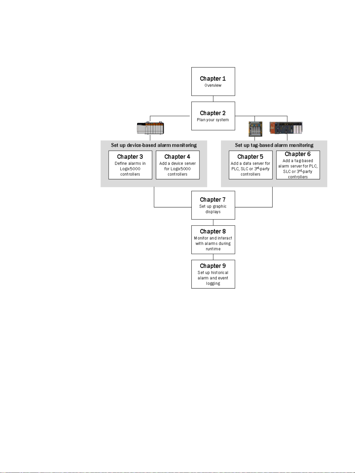
Where to start
8
Page 17
1 • Overview of FactoryTalk Alarms and Events services
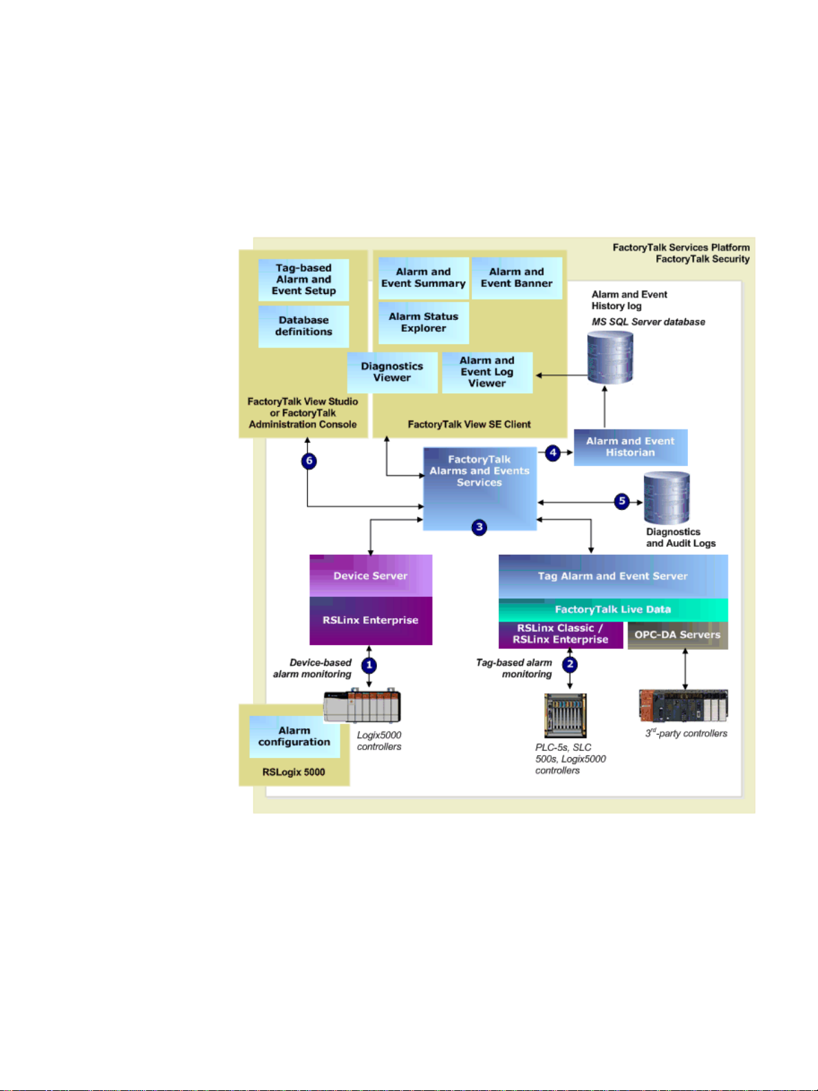
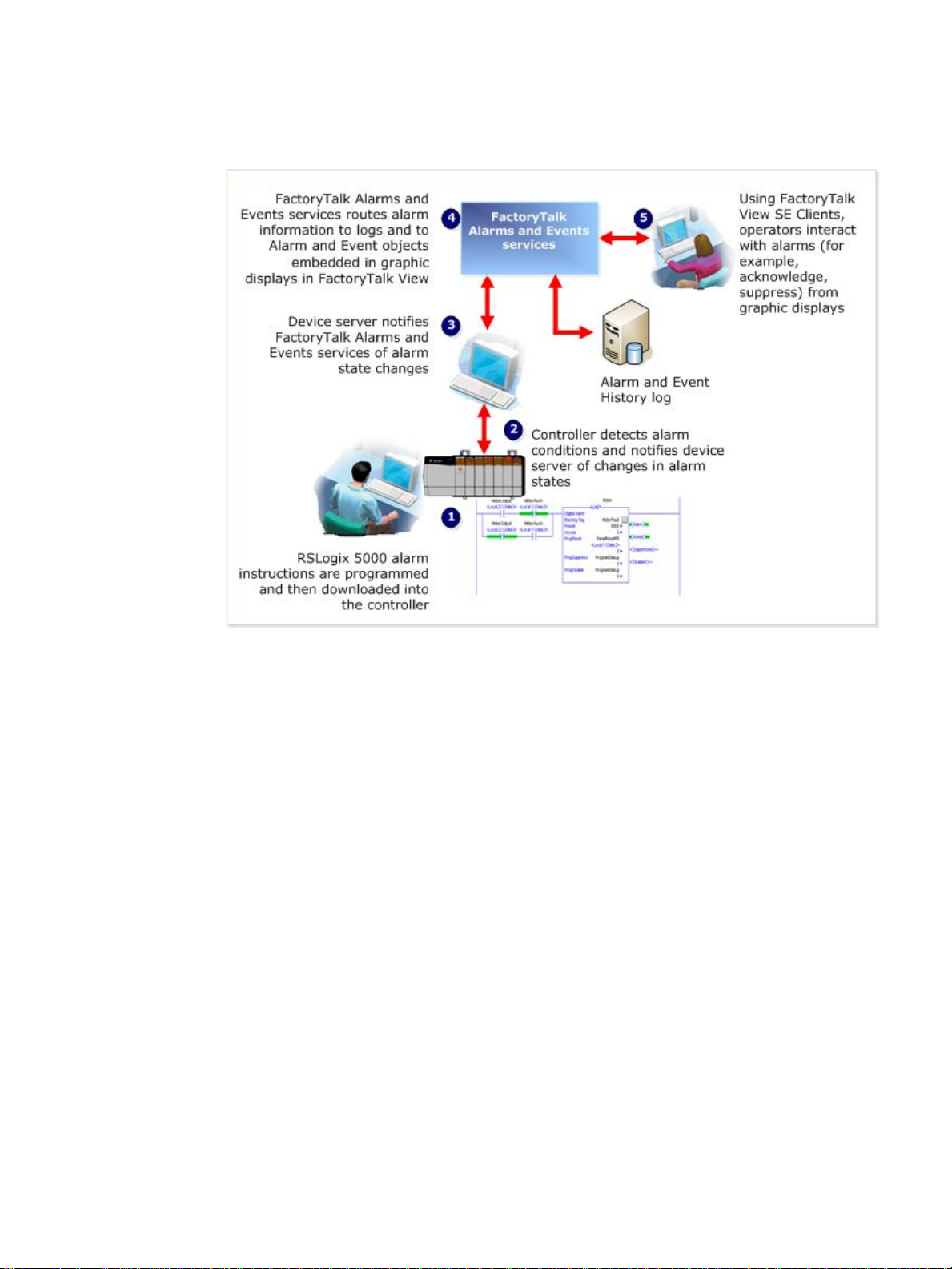
F actoryTalk Alarms and Events components
The following diagram shows a high-level view of the components of the FactoryTalk
Alarms and Events system. For more detailed information, see FactoryTalk Alarms
and Events Help (click Start, point to All Programs > Rockwell Software >
FactoryTalk Tools and then click FactoryTalk Help).
• • • • •
1. Device-based alarm monitoring
To do device-based alarm monitoring, you program alarm instructions, that are
available with RSLogix 5000 v . 16 or later , and then download them to Logix5000
controllers. The controller detects alarm conditions and notifies RSLinx
Enterprise of alarm states. A Rockwell Automation device server (RSLinx
Enterprise) extracts the alarm information and publishes it to FactoryTalk Alarms
and Events services.
9
Page 18

FactoryTalk Alarms and Events System Configuration Guide
• • • • •
Use device-based alarm monitoring with:
Logix5000 controllers, that you have programmed with RSLogix 5000 v. 16
or later software, and Rockwell Automation device servers (RSLinx
Enterprise).
2. Tag-based alarm monitoring
The Tag Alarm and Event Server uses tags to monitor programmable controllers
for alarm conditions. When an alarm condition is detected, the server publishes
the information to FactoryTalk Alarms and Events services.
Use tag-based alarm monitoring with:
PLC-5 or SLC 500 devices, and Rockwell Automation device servers
(RSLinx Enterprise).
RSLinx Classic or RSLinx Gateway.
Third-party controllers and OPC Data Servers.
Logix5000 controllers.
3. FactoryTalk Alarms and Events services
Both device-based and tag-based alarms and events are published to FactoryTalk
Alarms and Events services, which then routes the information to FactoryTalk
Alarms and Events objects hosted in FactoryTalk View, the alarm and event
history log, and to diagnostic logs and audit logs.
4. Alarm and Event Historian and Log
The Alarm and Event Historian is a logging component that installs silently as
part of the alarms and events software. It manages connections between alarm
servers and databases and logs data from each alarm server to an alarm history
database. You can use the Alarm and Event Log Viewer to view and print data
from alarm history databases. Third-party database tools can also retrieve, view,
analyze, and print alarm history information.
To use alarm and event logging, install Microsoft SQL Server 2005 Express SP2
separately, or use an existing Microsoft SQL Server 2000 SP4 or Microsoft SQL
Server 2005 database.
5. Diagnostic and audit logs
FactoryTalk Diagnostics routes messages generated by FactoryTalk Alarms and
Events to local logs on the computers hosting FactoryTalk components, and
optionally to a centralized database log. Audit messages are also routed to the
local log and to the FactoryT alk Audit Log if FactoryTalk AssetCentre is installed.
6. Alarm and event setup and monitoring
FactoryTalk Alarms and Events includes a number of software components that
allow engineers and operators to define alarm conditions, set up alarm servers,
view and interact with alarm conditions, and view and run reports on historical
alarm information.
10
Page 19

1 • Overview of FactoryTalk Alarms and Events services
Alarm and Event Summary
Use the Alarm and Event Summary object, embedded in a FactoryTalk View
graphic display, to acknowledge, disable, suppress, filter, and sort alarms at run
time.
Alarm and Event Banner
Use the Alarm and Event Banner object, embedded in a FactoryT alk View graphic
display, to monitor and respond to the most serious alarms that require immediate
attention.
Alarm Status Explorer
Use the Alarm Status Explorer object, embedded in a FactoryTalk View graphic
display, to enable or disable alarms, suppress or unsuppress alarms, and view
operator comments.
Database definitions
Use database definitions to define logging options from an alarm server to a
Microsoft SQL Server database.
• • • • •
Alarm and Event Log Viewer
Use the Alarm and Event Log Viewer object, embedded in a FactoryTalk View
graphic display, to view and filter historical alarm information stored in Microsoft
SQL Server databases.
Diagnostics Viewer
Use the Diagnostics Viewer to view, filter, and export system-generated
diagnostic messages. Run the Diagnostics Viewer from either FactoryTalk View
Studio or FactoryTalk Administration Console.
FactoryTalk Audit Log
Use the FactoryTalk Audit Log to view and manage audit messages routed by
FactoryTalk Diagnostics. To access the Audit Log, use RSMACC or FactoryTalk
AssetCentre software.
About monitoring for alarm conditions
You can monitor for alarm conditions in two ways — using software-based alarm
monitoring, or device-based alarm monitoring.
About software-based alarm monitoring
HMI tag alarm monitoring, offered by FactoryTalk View Site Edition, and tag-based
alarm monitoring, offered by FactoryTalk Alarms and Events, are both examples of
software-based alarm monitoring.
Software-based alarm monitoring is a generic way of monitoring alarms from legacy
or third-party cont
With software-based alarm monitoring, alarm de
rollers.
te
ction occurs in the controller, but
alarm monitoring is performed by software-based servers.
11
Page 20

FactoryTalk Alarms and Events System Configuration Guide
• • • • •
Tag-based alarm monitoring works like this (similar to HMI Tag Alarm
Monitoring):
This approach has several disadvantages:
Programming is required in both the controller and the HMI software or Tag
Alarm and Event Server.
Tags must be duplicated in the HMI server and mapped to the controller. For Tag
Alarm and Event Servers, controller tags must be mapped to alarms — in either
case, a tedious, error-prone process.
Alarms are detected and processed twice, first in the controller logic and then
again in the HMI software or Tag Alarm and Event Server.
Polling between the HMI server or Tag Alarm and Event Server and controller
tags increases network overhead.
Alarm time stamps are delayed because they are applied by the HMI server or Tag
Alarm and Event Server after polling and processing, rather than immediately
when they occur. Time stamps are not synchronized among multiple alarm
servers.
Alarm acknowledge and enable states are held in the computer, and not in the
controller. If the computer goes down, alarm state information is lost.
About device-based alarm monitoring
With device-based alarm monitoring, alarm detection also occurs in the controller, but
unlike software-based alarm monitoring, monitoring for alarm conditions is done in
the controller as well.
12
Page 21
1 • Overview of FactoryTalk Alarms and Events services
Device-based alarm monitoring works like this:
• • • • •
This approach has several advantages over software-based alarm detection:
Alarm instructions are programmed only once, and then downloaded to the
controller, which reduces programming effort and errors.
Alarm conditions are detected more quickly.
Alarms are detected at the same time the logic is being executed.
HMI tags or alarms in a Tag Alarm and Event Server are not required, which
reduces overhead and potential tag mapping errors.
Alarm state is managed, processed, and preserved by controllers, even if a
computer is stopped.
Data polling is eliminated and Alarm status is communicated only when state
changes, which reduces network overhead, controller processing, and improves
overall system performance.
Time stamps on alarm conditions are precise, because they are applied in the
controller, and not delayed until they reach the HMI software or Tag Alarm and
Event Server. However, all controllers that produce alarms must have their clocks
synchronized because device-based alarms are stamped with the controller’s time.
The event time is published throughout the FactoryTalk Alarms and Events
system, so inaccurate time stamps can affect where alarms are displayed in the
Alarm and Event Summary or the Alarm and Event Banner, as well as in reports
based on the alarm and event history. For more information about synchronizing
controller clocks, see Appendix G, “Time synchronization”.
13
Page 22

FactoryTalk Alarms and Events System Configuration Guide
• • • • •
Choosing between tag-based and device-based alarm monitoring
Use tag-based alarm monitoring with:
Logix5000 controllers
PLC-5, SLC 500 devices
Third-party controllers that communicate through OPC Data Servers
Use device-based alarm monitoring wi
Logix5000 controllers, using downloaded alarm instructions programmed
th:
with RSLogix 5000 v. 16 or later.
Graphic objects in FactoryTalk Alarms and Events
FactoryTalk Alarms and Events graphic objects are on the Objects menu in the
Graphics editor in FactoryTalk View Site Edition. The HMI tag alarm monitoring
objects remain available for compatibility with existing applications.
To do this
Acknowledge, disable,
suppress, filter, and sort
alarms at run time
Enable or disable alarms,
suppress or unsuppress
arms, and view operator
al
comments
In HMI tag alarm
monitor
this way
ing, you do it
HMI T ag Alarm Summary Alarm and Event
ag Alarm Summary
HMI T
(suppress only, using the
Execute feature)
SuppressOn and
SuppressOf
f commands
Suppressed list
With FactoryTalk
Alarms and Events, you
do it this way
Summary
Alarm and Event
Summary (
to unsuppress alarms, use
the Alarm Status
Explorer)
Alarm Status Explorer
suppress only;
14
Monitor and respond to
st serious alarms
the mo
that require immediate
attention
View, filter, and print
histori
cal alarm
information
Alarm system tags Alarm and Event Banner
HMI Ta g Alarm Log
Viewer
Alarms are logged to a
pr
etary format, and
opri
can be exported to an
ODBC-compliant
Alarm and Event Log
iew
er
V
Historical alarm
in
formatio
n is stored in
Microsoft SQL Server
databases.
database.
Page 23

Plan your system
Before you build and deploy FactoryTalk Alarms and Events as part of a local or
network application, consider which computer hardware and operating systems you
plan to use, as well as where to install the various hardware and software components.
The information in this chapter offers some guidelines as you begin planning. See also
“Required software” on page 1 and “Recommended hardware and supported
operating systems” on page 2.
Decide what type of application you are building
You must decide whether you are building a local application on a stand-alone
computer, or a network application distributed across multiple computers. This syst em
configuration guide discusses how to install, configure and use software on a standalone system.
FactoryTalk Alarms and Events is not supported for use with FactoryTalk View
Machine Edition.
Chapter 2
Network applications (sometimes called distributed applications) are held in a
FactoryTalk Network Directory, and organize project information from multiple
FactoryTalk products and services that are distributed across multiple computers
on a network. The applications you create in the Network Directory can be
divided into any number of areas and are available to all FactoryTalk products and
computers on a network. See “Typical distributed system on a network” on
page 215 for more information.
Local applications are suitable for self-contained, stand-alone processe s that do
not interact with other processes or systems. Local applications are held in a
FactoryTalk Local Directory, and are accessible only from the local computer
where they reside. Even if the computer is connected to a network, and even if a
network application resides on the same computer, the applications you create in
the FactoryTalk Local Directory remain self-contained and do not share data or
project elements.
Local applications do not support areas, and all application components and
participating software products are located on a single computer. See “Typical
stand-alone system” on page 18 for more information.
To use Alarms and Events with a local application, install all software on the same
computer.
15
Page 24

FactoryTalk Alarms and Events System Configuration Guide
• • • • •
Decide what type of alarm monitoring you need
FactoryTalk Alarms and Events supports two types of alarm monitoring:
Device-based alarm monitoring. Built-in alarm instructions, that are available in
RSLogix 5000 v. 16 or later, are programmed in a logic project and then
downloaded to a Logix5000 controller . The controller detects alarm conditions
and publishes event information, which can be displayed and logged.
Tag-based alarm monitoring. Software-based tag alarm and event servers
monitor controllers for alarm conditions through data servers and publish event
information, which can be displayed and logged. Tag-based alarm monitoring is
supported for Logix5000, PLC-5, and SLC 500 devices communicating through
Rockwell Automation device servers (RSLinx Enterprise), or for third-party
controllers that communicate through OPC Data Servers.
You can use a mix of both types of alarm monitoring. Choose tag-based alarm
monito
Choose tag-based alarm monitoring, if you do not want to update the firmware in
Logix5000 controllers.
ring if you do not want to change the logic in your programmable controllers.
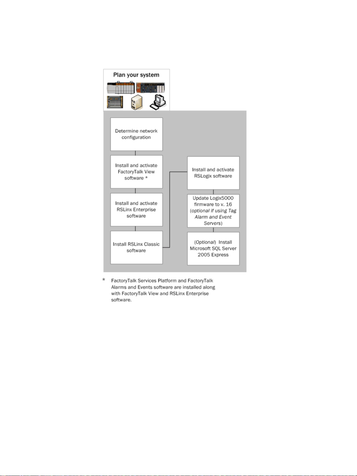
What you need
Decide what type of application you are building.
Decide what type of alarm monitoring you need.
Install and activate FactoryTalk software.
Update Logix5000 firmware to version 16 if you plan to use device-based alarm
monitoring and alarm instructions that are built into Logix5000 controllers. If you
do not plan to use device-based alarm instructions, you can skip this step and use
tag-based alarm monitoring with a Tag Alarm and Event Server instead.
16
Page 25
F ollow these steps
• • • • •
2 • Plan your system
17
Page 26
FactoryTalk Alarms and Events System Configuration Guide
• • • • •
Install and activate FactoryTalk software
Follow these procedures to install and activate the software products required for
FactoryTalk Alarms and Events.
This guide describes how to set up a local application. The procedure to set up a
network application is similar. This guide provides additional information about
Network applications where it is necessary. See also
building a distributed system”.
For more information about each software product, see that product’s Help.
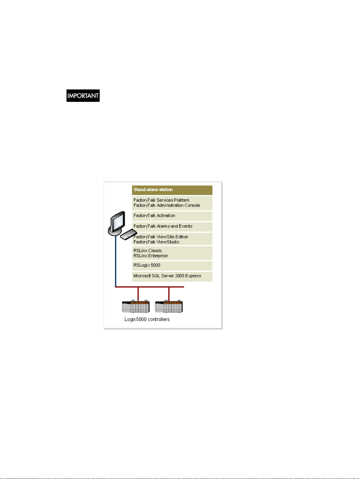
Typical stand-alone system
T o use FactoryT alk Alarms and Events with a local application as part of a stand-alone
FactoryTalk system, install all software on the same computer. Use this diagram only
as a starting point; your own system will vary.
Appendix H, “Reference for
18
Page 27

Install FactoryTalk software
For specific installation instructions, refer to the installation guide for each product.
• • • • •
2 • Plan your system
If you plan to build local applications, in
stall everything on one computer.
If you plan to build network applications distributed a
FactoryT alk Help (S tart > All Pr ograms > Rockwell Softwar e > FactoryTalk T ools
> FactoryTalk Help) for instructions.
To set up a FactoryTalk system, install this software:
FactoryTalk Services Platform
FactoryTalk Activation
FactoryTalk View Site Edition
RSLinx Enterprise
RSLinx Classic
RSLogix 5000
Update Logix5000 firmware to version 16 (if you plan to use device-based alarm
monitoring — see “Decide what type of alarm monitoring you need” on page 16)
Install Microsoft SQL Server 2005 Express
If you plan to log historical alarm and event messages to a database, you must install
Microsoft SQL Server software on the computer you want to use for logging. We
recommend that to install Microsoft SQL Server 2005 Express (SP2) you use the
batch file that is available on both the FactoryTalk View and RSLinx Enterprise
installation CDs, in the Redist folder. For installation instructions, see “Install
Microsoft SQL Server 2005 Express” on page 183
cross multiple computers, see
.
If you already have Microsoft SQL Server 2000 (SP4) or 2005 installed, you may need
to change the configuration options to log alarm and event messages. For
configuration instructions, see “Use an existing Microsoft SQL Server database” on
page 191.
19
Page 28

FactoryTalk Alarms and Events System Configuration Guide
• • • • •
20
Page 29

Chapter 3
Define device-based alarms in Logix5000 controllers
To set up device-based alarm monitoring, you program alarm instructions, that are
available with RSLogix 5000 v. 16 or later , and download them to a Logix5000
controller. The controller detects alarm conditions and notifies alarms and events
services of alarm states. Software components publish this information to a device
server, where it can be logged to a database, and viewed, acknowledged, suppressed,
enabled, or disabled from FactoryTalk View graphic displays.
FactoryTalk Alarms and Events can handle many different types of alarms. The
controller limits the al
monitors two types of alarm conditions: Level and Rate of Change. A tag-based alarm
server supports three alarm types: Digital, Level and Deviation.
arms to digital and analog. An analog alarm instruction
A digital alarm instruction is based on the input ru
alarm input (for function block). The trigger condition compares the value of the tag to
either zero or one.
An analog alarm defines a condition that evaluates a single a
four limit values (high-high to low-low) and up to two rate of change limits (positive
and negative).
If your FactoryTalk application does not include Logix5000 controllers, or if your
controllers are not programmed with the new alarm instructions included in RSLogix
5000 v. 16 or later, see Chapter 5, “Add an OPC Data Server for third-party
controllers” and Chapter 6, “Add a tag-based alarm server for Logix5000, PLC-5,
SLC 500, or third-party controllers”.
ng state (in ladder logic) or on the
nalog tag against up to
Alarm buffering during loss of connection to the controller
To receive device-based alarms, the alarm server (RSLinx Enterprise) establishes a
subscription to the alarms in the Logix controller. The controller maintains a
connection to each subscriber and monitors the status of that connection.
che
As alarm state changes occur, the controller ca
alarm state and associated tag values, and transmits the information to all of the
subscribers.
If any subscriber fails to confirm the receipt of the
connection to a subscriber is not good, the controller stores the undelivered alarm
information in a 100 KB buffer. Each subscriber has its own buffer and
communication problems with one subscriber do not interfere with alarm delivery to
other subscribers. When the buffer is full, newer alarm information is discarded and a
FactoryT alk Diagnostics message is logged. The buf fer is created when the subscriber
establishes its initial connection, and is maintained for a length of time after a
subscriber loses its connection. The length of time is specified in the Buffer Timeout
setting on each RSLinx Enterprise device shortcut. See Chapter 4, “Create a new
shortcut to the controller”.
s information such as timestamps,
alarm information, or if the
21
Page 30

FactoryTalk Alarms and Events System Configuration Guide
• • • • •
Before you begin
Review Chapter 2, “Plan your system”.
Verify that you have installed and activated the software listed next under “What
you need”.
Verify that the Logix5000 firmware has been updated to version 16.
What you need
RSLogix 5000
ControlFLASH
RSLinx Classic
22
Page 31

F ollow these steps
• • • • •
3 • Define device-based alarms in Logix5000 controllers
23
Page 32

FactoryTalk Alarms and Events System Configuration Guide
• • • • •
Define a digital alarm
Digital tags are either on or off. They have states instead of limits. The alarm trigger
condition compares the value of the tag to the configured alarm state. An alarm can be
triggered if the digital alarm is in one of these two states:
the rung evaluation or input tag is equal to zero
the rung evaluation or input tag is not equal to zero
If your FactoryTalk application does not include Logix5000 controllers, or if your
controllers are not programmed with the new alarm instructions included in RSLogix
5000 v. 16 or later, see Chapter 5, “Add an OPC Data Server for third-party
controllers” and Chapter 6, “Add a tag-based alarm server for Logix5000, PLC-5,
SLC 500, or third-party controllers”.
Configure the alarm and download to the controller
This example uses the ladder logic editor that comes with RSLogix 5000 to define a
digital alarm. You can also configure digital alarms in function blocks or structured
text.
Step 1: Start RSLogix 5000 and then create a new project
1. T o run RSLogix 5000 v. 16 or later software, click Start, point to All Programs >
Rockwell Software > RSLogix 5000 Enterprise Series and then click
RSLogix 5000.
2. On the File menu, click New to create a new project.
3. In the New Controller dialog box, enter information for the type of controller you
are using. Keep the default location in the Create-In field. For help with filling in
the dialog box, click Help.
24
4. In the Name field, type a name for the new controller. In the example above, we
West_Plant_Controller.
used
Page 33

3 • Define device-based alarms in Logix5000 controllers
5. Click OK to save the configuration and open it in RSLogix 5000, as shown here.
• • • • •
Step 2: Create a rung of logic that will trigger the alarm
1. In the left pane, expand the folders Tasks > MainTask > MainProgram, and then
double-click MainRoutine.
25
Page 34

FactoryTalk Alarms and Events System Configuration Guide
• • • • •
2. On the Language Element toolbar, click the Examine-on instruction button
(shown at left) to add it to a rung on the ladder project.
3. At the top of the Examine-on instruction, click the question mark to select it. On
the File menu, click New Component, and then click Tag.
26
Page 35

3 • Define device-based alarms in Logix5000 controllers
4. In the New Tag dialog box, type a name for the tag, choose BOOL as the data
type, and then click OK.
• • • • •
In our example, we named the tag
alarm_active.
Step 3: Add a digital alarm instruction to the rung
1. On the Language Element toolbar, click the Alarms tab, and then click the
ALMD button (shown at left). The instruction block is placed in the ladder logic.
2. Inside the alarm instruction, beside ALMD, select the question mark.
3. On the File menu, click New Component, and then click Tag.
27
Page 36

FactoryTalk Alarms and Events System Configuration Guide
• • • • •
4. In the New Tag dialog box, type a name for the digital alarm tag, and then click
OK.
In our example, we named the tag
DigitalAlarm1.
Step 4: Specify a tag for each of the digital alarm’s operands,
or just enter
0
1. Inside the alarm instruction, select the ProgAck operand.
2. On the File menu, click New Component, and then click Tag.
3. In the New T ag dialog box, type a name for th e tag, select BOOL as the data type,
and then click OK.
In our example, we named the tag
New Tag dialog box, click Help.
DigitalAlarm1_Ack. For details about using the
28
Page 37

3 • Define device-based alarms in Logix5000 controllers
4. Create tags for the ProgReset, ProgDisable, and ProgEnable operands. When you
are finished, the alarm instruction should resemble the one shown here:
• • • • •
Step 5: Configure the properties of the new digital alarm tag:
1. Inside the alarm instruction, click the Browse button (shown at left).
2. In the ALMD Properties dialog box, specify configuration settings, and then
click OK. For help with specifying configuration settings, click Help.
To create a text message with embedded variables for each alarm, click the Browse
button beside the Message box. At run time, these messages appear in Alarm and
Event graphic objects, such as the Alarm and Event Summary. The maximum length
of an alarm message is 255 characters. When importing alarm messages, RSLogix
5000 will verify the message length and display a warning if the alarm message
exceeds the character limit.
29
Page 38

FactoryTalk Alarms and Events System Configuration Guide
• • • • •
Step 6: Download the prog ram containing the ladder logic to the controller
1. If it is not already running, start RSLinx Classic to establish communications
between RSLogix 5000 v. 16, or later, and the controller.
2. On the RSLogix 5000 menu, click Communications > Who Active.
3. If it is not already highlighted, select the controller to which you want to
download the project.
In this example, use the same controller you configured for the
West_Plant_Controller project in “Start RSLogix 5000 and then create a new
project” on page 24.
30
Page 39

3 • Define device-based alarms in Logix5000 controllers
4. Click Download. At the prompt, click Download again. The controller is placed
in Program mode.
Step 7: Test the alarm instruction by switching to run mode and triggering
the alarm
• • • • •
1. On the RSLogix 5000 menu, click Communications > Run Mode. Click Yes to
switch the controller to run mode.
31
Page 40

FactoryTalk Alarms and Events System Configuration Guide
• • • • •
2. To trigger the alarm, right-click the contact on the rung (the one we named
“alarm_active”). On the context menu, click Toggle Bit. The contact should
change from a blue highlight to a green highlight.
Step 8: Finish creating alarms, and next steps
1. Define additional digital alarms or analog alarms, using either ladder logic,
function blocks, or structured text, and download the logic to the controller.
2. When you finish defining alarms, create a device-based alarm server, and then
configure it to subscribe to events detected by the Logix5000 controller. See
Chapter 4, “Add a device server for Logix5000, PLC-5, or SLC 500 controllers”
for instructions.
Define an analog alarm
An analog alarm defines a condition that evaluates a single analog tag against up to
four limit values (high-high to low-low) and up to two rate of change limits (positive
and negative).
If your FactoryTalk application does not include Logix5000 controllers, or if your
controllers are not programmed with the new alarm instructions included in RSLogix
5000 v. 16 or later, see
controllers” and Chapter 6, “Add a tag-based alarm server for Logix5000, PLC-5,
SLC 500, or third-party controllers”.
Chapter 5, “Add an OPC Data Server for third-party
32
Page 41

3 • Define device-based alarms in Logix5000 controllers
Configure the alarm and download it to the controller
This example uses the Function Block editor that comes with RSLogix 5000. You can
also configure analog alarms in ladder logic or structured text.
Step 1: Start RSLogix 5000 and then create a new project
1. Run RSLogix 5000 v. 16 or later software.
2. On the File menu, click New.
3. In the New Controller dialog box, select the required controller type from the
Type list and then type a name for the new controller in the Name0 field.
• • • • •
In this example, we used
East_Plant_Controller.
33
Page 42

FactoryTalk Alarms and Events System Configuration Guide
• • • • •
4. Click OK to save the configuration and open it in RSLogix 5000, as shown here.
Step 2: Define a new routine
1. In the left pane, expand the Tasks folder, right-click MainProgram, and then
click New Routine on the context menu.
34
Page 43

3 • Define device-based alarms in Logix5000 controllers
2. In the New Routine dialog box, type a name for the routine. We used
alarm_active.
3. In the Type list, click Function Block Diagram.
4. Select the Open Routine check box, and then click OK.
The new routine appears in the Tasks folder under MainRoutine and the routine
opens on the right side of the RSLogix 5000 window:
• • • • •
35
Page 44

FactoryTalk Alarms and Events System Configuration Guide
• • • • •
Step 3: Build the function block logic
1. To add an alarm block, go to the tabs in the center right area (Favorites, Add-On,
and so on) as shown in the following illustration. Scroll to the right, and then click
the Alarms tab.
2. On the toolbar, click the ALMA but
block, as shown in the following illustration.
ton (shown at left) to add an Analog Alarm
36
Page 45

3 • Define device-based alarms in Logix5000 controllers
3. Using the same Alarm objects on the Language Element toolbar, click the Input
Reference icon (shown at left). An Input Reference tag appears in the Function
Block editor:
• • • • •
4. Right-click the single question mark inside the symbol and then click New Tag.
37
Page 46

FactoryTalk Alarms and Events System Configuration Guide
• • • • •
5. In the New Tag dialog box, type a name for the tag and then click OK.
In this example, we used
AnalogAlarm1.
The screen should resemble the one shown in the following illustration:
38
Page 47

3 • Define device-based alarms in Logix5000 controllers
6. Connect the input reference block to the Input of the ALMA block, as shown in
the following illustration, by dragging the block’s contact point to the contact
point on the ALMA block.
• • • • •
39
Page 48

FactoryTalk Alarms and Events System Configuration Guide
• • • • •
Step 4: Configure the properties of the alarm block
1. Click the Browse button on the alarm block.
2. In the ALMA Properties dialog box, set the Input Levels as shown in the
following illustration and then click OK. To require that an operator acknowledge
the alarm at run time, make sure the Acknowledgement Required check box is
selected.
40
To enter alarm messages and add variables for analog alarms, select the Messages
tab. To create a text message with embedded variables, click the Browse button
beside the Level field, or beside the Rate of Change field. At run time, alarm
messages are displayed in Alarm and Event graphic objects suc h as the Alarm and
Event Summary.
Page 49

3 • Define device-based alarms in Logix5000 controllers
Step 5: Add a JSR instruction to the MainRoutine to run the function block:
1. Double-click MainRoutine to open it.
2. Right-click the first rung and then click Add Ladder Element on the context
menu.
3. In the Add Ladder Element dialog box, scroll down to the Program Control
folder and then double-click the folder to expand the list of controls.
• • • • •
4. Select JSR and then click OK.
5. In the JSR instruction, double-click Routine Name and then click alarm_active in
the list.
6. On the toolbar, click the Save button to save the configuration.
41
Page 50

FactoryTalk Alarms and Events System Configuration Guide
• • • • •
Step 6: Download the pro g ram to the controller
1. If it is not already running, start RSLinx Classic to establish communications
between RSLogix 5000 v. 16, or later, and the controller.
2. On the RSLogix 5000 menu, click Communications > Who Active.
3. Select the controller to which you want to download the project.
4. Click Download. At the prompt, click Download again.
5. To switch the controller to run mode, on the RSLogix 5000 menu, click
Communications > Run Mode.
Step 7: Finish creating alarms, and next steps
Define additional digital alarms or analog alarms using either ladder logic,
function block, or structured text, and download the logic to the controller.
When you finish defining alarms, create a device-based alarm server, and then
configure it to subscribe to events detected by the Logix5000 controller. See
Chapter 4, “Add a device server for Logix5000, PLC-5, or SLC 500
controllers”.
42
Page 51

Chapter 4
Add a device server for Logix5000, PLC-5, or SLC 500
controllers
To use device-based alarms in Logix5000 controllers, or tag-based alarms in PLC-5,
SLC 500, or Logix5000 controllers you must add a device server to your application.
FactoryTalk Alarms and Events supports two types of alarm monitoring:
Device-based alarm monitoring. Built-in alarm instructions, that are available in
RSLogix 5000 v. 16 or later, are programmed in a logic project and then
downloaded to a Logix5000 controller . The controller detects alarm conditions
and publishes event information, which can be displayed and logged.
Tag-based alarm monitoring. Software-based tag alarm and event servers
monitor controllers for alarm conditions through data servers and publish event
information, which can be displayed and logged. Tag-based alarm monitoring is
supported for Logix5000, PLC-5, and SLC 500 devices communicating through
Rockwell Automation device servers (RSLinx Enterprise), or for third-party
controllers that communicate through OPC Data Servers.
You can use a mix of both types of alarm monitoring. Choose tag-based alarm
nito
mo
Choose tag-based alarm monitoring, if you do not want to update the firmware in
Logix5000 controllers.
ring if you do not want to change the logic in your programmable controllers.
Before you begin
If you are using device-based alarms, define your alarms, as shown in Chapter 3,
“Define device-based alarms in Logix5000 controllers”.
If you are using tag-based alarms, you can create a controller program to detect
alarm conditions and then communicate them through tags that are monitored by
the FactoryTalk Tag Alarm and Event Server.
What you need
RSLinx Enterprise
FactoryT alk View Studio or FactoryTalk Administration Console
This guide uses FactoryTalk View Studio to define a device server. You can also use
FactoryTalk Administration Console. For more information, select Help > Contents
from the FactoryTalk Administration Console window.
43
Page 52

FactoryTalk Alarms and Events System Configuration Guide
• • • • •
F ollow these steps
44
Page 53

Add a device s erver
In this section, you will create a Rockwell Automation device server (RSLinx
Enterprise) and then configure it to subscribe to alarms that will be detected by a
Logix5000 controller.
If you are using third-party controllers, you do not need a device-based alarm
server. Instead, go to
controllers”.
Step 1: Create an application in FactoryTalk View Studio
This example shows how to create a local application.
• • • • •
4 • Add a device server for Logix5000, PLC-5, or SLC 500 controllers
Chapter 5, “Add an OPC Data Server for third-party
1. To start FactoryTalk View Studio, on the Windows Start menu, click Star
t, point
to All Programs > Rockwell Software > FactoryTalk View and then click
FactoryTalk View Studio.
2. In the Application Type Selection window, select Site Edition (Local) and then
click Continue.
FactoryTalk View Machine Edition does not support FactoryTalk Alarms and Events.
45
Page 54

FactoryTalk Alarms and Events System Configuration Guide
• • • • •
3. In the New/Open Site Edition (Local) Application dialog box click the New tab.
4. In the Application name field, type a name for the new Local application. In this
example, we named the application
My Local Site.
5. Leave the Description field blank, or type a description for the application. For
example, you can use this field to record revisions to the application, or contact
information for technical support.
6. If it is not already selected, select the default language for the application. This is
the language in which you are creating the applica tion.
7. Click Create.
8. In the Add Process Faceplates dialog box, click Clear All and then click OK.
46
If you have cleared the “Display this dialog when creating a new application” check
box, the Add Process Faceplates dialog box does not open automatically. To open it
manually, in the Explorer window right-click the HMI server and then select Add
Process Faceplates from the context menu.
Page 55

4 • Add a device server for Logix5000, PLC-5, or SLC 500 controllers
Step 2: Configure the device server
1. In the Explorer window, right-click the new application (My Local Site). On the
context menu, point to Add New Server, and then click Rockwell Automation
Device Server (RSLinx Enterprise).
• • • • •
2. In the RSLinx Enterprise Server Properties dialog box, click the General tab,
type a name for the new server, and then click Apply.
In this example, we named the server FTAE Server.
47
Page 56

FactoryTalk Alarms and Events System Configuration Guide
• • • • •
3. If you plan to use tag-based alarms, skip the rest of the steps in this section, and go
on to “Create a new shortcut to the controller” on page 49. If you are using built-in
alarm instructions in Logix5000 controllers, on the Alarms and Events tab, select
the Enable alarm and event support check box.
48
4. Clear the Enable history check box and then click OK. For information about
historical logging, see Chapter 9, “Set up historical alarm and event logging”.
The new server is added to the
My Local Site application:
Page 57

4 • Add a device server for Logix5000, PLC-5, or SLC 500 controllers
Step 3: Create a new shortcut to the controller
1. In the Explorer window, double-click the new RSLinx Enterprise server (in our
example we named it FTAE Server), and then double-click Communication
Setup.
• • • • •
2. In the Communication Setup dialog box, click the Add button, and then type a
name for the new shortcut. We used FTAE_Controller.
Some options in this dialog box might be different if you are using PLC-5 or SLC
500 controllers.
The warning icon beside the OK button indicates that changing values in this
dialog box at run time can cause unexpected results. For details, see Help.
49
Page 58

FactoryTalk Alarms and Events System Configuration Guide
Set the Buffer Timeout
setting for the length of
time (zero to 120) you
want to cache alarm
information if the
connection to the
controller is lost. To
disable alarm buffering
set the value to zero.
(See “Alarm buffering
during loss of connection
• • • • •
3. Skip this step if you do not plan to use Logix5000 controllers with built-in alarm
instructions. In the Enable list, click Yes to enable Alarms and Events:
4. On the Primary tab, expand the list of networks and devices until the controller
you plan to use is visible, and then click the controller.
50
5. To set the path to the primary controller, click the Apply button.
6. T o save the shortcut configuration and close the Communication Setup dialog
box, click OK.
Page 59

4 • Add a device server for Logix5000, PLC-5, or SLC 500 controllers
Step 4: Finish creating data servers, and next steps
1. If your FactoryTalk application includes third-party OPC-DA controllers, add an
OPC Data Server, create a tag-based alarm server, and then define alarms. See
Chapter 5, “Add an OPC Data Server for third-party controllers” and Chapter 6,
“Add a tag-based alarm server for Logix5000, PLC-5, SLC 500, or third-party
controllers”.
2. If your FactoryTalk application is communicating with PLC-5 or SLC 500
controllers, or Logx5000 controllers that are not using built-in alarm instructions,
you must add a device server (RSLinx Enterprise) to your application and then
create a tag-based alarm server and define alarms. See Chapter 6, “Add a tagbased alarm server for Logix5000, PLC-5, SLC 500, or third-party controllers”.
3. After you create data servers and alarms, add FactoryTalk Alarm and Event
objects to graphic displays. See Chapter 7, “Set up graphic displays”.
• • • • •
51
Page 60

FactoryTalk Alarms and Events System Configuration Guide
• • • • •
52
Page 61

Chapter 5
Add an OPC Data Server for third-party controllers
To monitor alarms in a third-party controller, create a controller program to detect
alarm conditions and communicate them to tags. Use an OPC Data Server (for
example, KEPWare server) to obtain tag values from the controller, and use a Tag
FactoryTalk Alarm and Event Server to monitor those tags for alarm conditions.
This chapter describes how to use RSLinx Class
situations you will use RSLinx Enterprise to communicate with a PLC-5 or SLC 500
controller.
However, you might need to use RSLinx Classic to communicate with a
controller that is bridged over Ethernet to a DH+ or DH-485 network.
Before you begin
Review Chapter 2, “Plan your system”
Verify that you have installed and activated the software listed next under “What
you need”
What you need
PLC-5, SLC 500 or third-party OPC-DA programmable controller
RSLogix 5 or RSLogix 500 software
RSLinx Classic software
RSLinx Enterprise software
FactoryT alk View Studio or FactoryTalk Administration Console
ic as an OPC Data Server
. In most
53
Page 62

FactoryTalk Alarms and Events System Configuration Guide
• • • • •
F ollow these steps
54
Add an OPC Data Server to an application
When you add a data server to an application or area, tags published by the data server
can be accessed by any client — in this case, the Tag Alarm and Event Server.
This guide uses FactoryTalk View Studio to add a data server. You can also use
FactoryTalk Administration Console. For more information, select Help > Contents
from the FactoryTalk Administration Console window.
Page 63

5 • Add an OPC Data Server for third-party controllers
Step 1: Open an existing application in FactoryTalk View Studio
1. T o run FactoryTalk View Studio on the Windows Start menu, click Start, point
to All Programs > Rockwell Software > FactoryTalk View and then click
FactoryTalk View Studio.
2. In the Application Type Selection window, select Site Edition (Local) and then
click Continue.
3. In the New/Open Site Edition (Local) Application dialog box, click the
Existing tab, and select the application you created in Chapter 4, “Add a device
server for Logix5000, PLC-5, or SLC 500 controllers” (we used My Local Site).
• • • • •
Step 2: Add a data server
1. In the Explorer window, right-click the application, point to Add New Server,
and then click OPC Data Server.
2. In the OPC Data Server Properties dialog box, type a name for the server. This
example uses My OPC Server.
3. Beside the OPC Server name (ProgID) field, click the Browse button.
55
Page 64

FactoryTalk Alarms and Events System Configuration Guide
• • • • •
4. In the A vailable OPC Data Servers dialog box, select RSLinx OPC Server, and
then click OK.
When creating a Network application, select RSLinx Remote OPC Server.
5. Click OK again to close the OPC Data Server Properties dialog box.
6. Next, add a T ag Alarm and Event Server and define alarm conditions. See Chapter
6, “Add a tag-based alarm server for Logix5000, PLC-5, SLC 500, or third-party
controllers”.
56
Page 65

Chapter 6
Add a tag-based alarm server for Logix5000, PLC-5,
SLC 500, or third-party controllers
FactoryTalk Tag Alarm and Event Servers provide software-based alarms and events.
Use tag alarm and event servers to monitor alarm conditions in Logix5000 controllers,
PLC-5, SLC 500, or third-party OPC-DA programmable controllers.
FactoryTalk Ta g Alarm and Event Servers also provide an alternative to device-based
alarms, for example, alarms provided by devices
controllers using built-in alarm instructions.
such as sensors or Logix5000
A FactoryTalk Tag Alarm and Event Server can also detect alarm conditions
party controllers. All that is required is a data server (such as KEPWare) to
communicate with the controller.
A FactoryTalk Tag Alarm and Event Server provides a link between a hardware
vice
that contains data and the FactoryTalk Directory.
de
If your FactoryTalk system does not include PLC, SLC, or third-party controllers, you
can skip this chapter.
You can create and edit:
digital alarms
level alarms
deviation alarms
For each alarm, you can also create and edit a
within the message. For details, click the Help button on the dialog box.
Before you begin
If you are using third-party controllers, you do not need a device-based alarm
server. Instead, go to Chapter 5, “Add an OPC Data Server for third-party
controllers”.
in third-
text message and embed variables
What you need
Logix5000 controllers, PLC-5, or SLC 500 devices communicating through
Rockwell Automation device servers (RSLinx Enterprise)
RSLogix 5 or RSLogix 500 software
RSLinx Enterprise, RSLinx Classic (or RSLinx Classic for bridging from
Ethernet to DH+ or DH-485 networks)
FactoryT alk View Studio or FactoryTalk Administration Console
57
Page 66

FactoryTalk Alarms and Events System Configuration Guide
• • • • •
F ollow these steps
58
Page 67

6 • Add a tag-based alarm server for Logix5000, PLC-5, SLC 500, or third-party controllers
Create an application
In this section, you will create a Rockwell Automation device server (RSLinx
Enterprise) and then configure it to subscribe to alarms that will be detected by a
Logix5000 controller. In this example, the Rockwell Automation device server
(RSLinx Enterprise) is used as a data server for tag values, not as an alarm server.
Step 1: Create an application in FactoryTalk View Studio
If you created a local application previously, you can skip this step.
Instead, open FactoryTalk View Studio, in the Application Type Selection window,
select Site Edition (Local) and then click Continue. In the New/Open Site Edition
(Local) Application dialog box, click the Existing tab, and select the application
you created.
This example shows how to create a local application.
1. To start FactoryTalk View Studio, on the Windows Start menu, click Start, point
to All Programs > Rockwell Software > FactoryTalk View and then click
FactoryTalk View Studio.
• • • • •
2. In the Application Type Selection window, select Site Edition (Local) and then
click Continue.
FactoryTalk View Machine Edition does not support FactoryTalk Alarms and Events.
59
Page 68

FactoryTalk Alarms and Events System Configuration Guide
• • • • •
3. In the New/Open Site Edition (Local) Application dialog box click the New tab.
4. In the Application name field, type a name for the new Local application. In this
example, we named the application
My Local Site.
5. Leave the Description field blank, or type a description for the application. For
example, you can use this field to record revisions to the application, or contact
information for technical support.
6. If it is not already selected, select the default language for the application. This is
the language in which you are creating the applica tion.
7. Click Create.
8. In the Add Process Faceplates dialog box, click Clear All and then click OK.
60
If you have cleared the “Display this dialog when creating a new application” check
box, the Add Process Faceplates dialog box does not open automatically. To open it
manually, in the Explorer window right-click the HMI server and then select Add
Process Faceplates from the context menu.
Page 69

6 • Add a tag-based alarm server for Logix5000, PLC-5, SLC 500, or third-party controllers
Add a data server
Step 1: Configure the device server (RSLinx Enterprise)
When you add a data server to an application or area, tags published by the data server
can be accessed by any client — in this case, the Tag Alarm and Event Server.
This guide uses FactoryTalk View Studio to add a data server. You can also use
FactoryTalk Administration Console. For more information, select Help > Contents
from the FactoryTalk Administration Console window.
In this example a device server (RSLinx Enterprise) is added to the application to act
as a data server.
• • • • •
1. In the Explorer window, right-click the application (My Local
context menu, point
to Add New Server, and then click Rockwell Automation
Site). On the
Device Server (RSLinx Enterprise).
2. In the RSLinx Enterprise Server Properties dialog box, click the General tab,
type a name for the server, and then click Apply. In this example, we named the
server FTAE Server.
The new server is added to the
My Local Site application:
61
Page 70

FactoryTalk Alarms and Events System Configuration Guide
• • • • •
Step 2: Create a new shortcut to the controller
If you already created a shortcut to the controller in a previous chapter, you can
skip this step.
1. In the Explorer window, double-click the new RSLinx Enterprise server (in our
example we named it FTAE Server), and then double-click Communication
Setup.
62
Page 71

6 • Add a tag-based alarm server for Logix5000, PLC-5, SLC 500, or third-party controllers
2. In the Communication Setup dialog box, click the Add button, and then type a
name for the new shortcut. We used FTAE_Controller.
• • • • •
Some options in this dialog box might be different if you are using PLC-5 or SLC
500 controllers.
The warning icon beside the OK button indicates that changing values in this
dialog box at run time can cause unexpected results. For details, see Help.
3. On the Primary tab, expand the list of networks and devices until the controller is
visible, and then click the controller. To set the path to the primary controller,
click the Apply button.
4. T o save the shortcut configuration and close the Communication Setup dialog
box, click OK.
63
Page 72

FactoryTalk Alarms and Events System Configuration Guide
• • • • •
Add a Tag Alarm and Event Server
T o create a server and define alarm conditions that monitor tags for PLC-5 or SLC 500
controllers, and Logix5000 controllers, complete the following steps.
These instructions apply to FactoryTalk View Studio. For help with FactoryTalk
Administratio
Start, point to All Programs > Rockwell Software > FactoryTalk Tools, and then
click FactoryTalk Help.
Step 1: Add a Tag Alarm and Event Server
1. In the Explorer window, right-click the application. On the context menu, point to
Add New Server, and then click Tag Alarm and Event Server.
2. In the Tag Alarm and Event Server Properties dialog box, click the General
tab.
n Console, see FactoryTalk Help. On the Windows Start menu, click
3. Type a name for the server, and then click OK. In this example, we used
4. On the Priorities and History tab, clear the Enable history check box.
The Priorities and History tab is used to configure alarm and event logging.
Chapter 9, “Set up historical alarm and event logging” describes how to set up
alarm logging for an Tag Alarm and Event Server.
TagAE.
64
5. To create the Tag Alarm and Event Server and close the dialog box, click OK.
Page 73

6 • Add a tag-based alarm server for Logix5000, PLC-5, SLC 500, or third-party controllers
Define alarm conditions
After you create a Tag Alarm and Event Server, you define the conditions that will
trigger alarms at run time.
This example shows how to create a digital alarm in a Tag Alarm and Event Server.
1. In the Explorer window, expand the TagAE server, and then double-click Alarm
and Event Setup.
2. In the Alarm and Event Setup dialog box, click the New button on the toolbar,
and then click Digital.
• • • • •
3. In the Digital Alarm Properties dialog box, type a name for the alarm. In this
example we used Valve1FTO.
4. T o select an Input Tag for the alarm, click the browse button, and then expand the
folder folder tree until you can select the online tag you plan to monitor.
65
Page 74

FactoryTalk Alarms and Events System Configuration Guide
• • • • •
5. Select the tag you plan to monitor and then click OK. In this example we used
Valve1FTO_alm.
6. In the Digital Alarm Properties dialog box, type a message. In this example we
typed ‘The valve failed to open.’ in the Message field.
You can also embed variables within the message. For details, click the Help
button on any tab in the Alarm Setup dialog box.
66
Page 75

6 • Add a tag-based alarm server for Logix5000, PLC-5, SLC 500, or third-party controllers
7. To close the Digital Alarm Properties dialog box, click OK.
8. To save the alarm and start monitoring for the alarm condition, click the Save
button.
Next steps
1. Define additional alarms.
2. After you define alarms, you can add FactoryTalk Alarm and Event objects to
graphic displays. See Chapter 7, “Set up graphic displays”.
• • • • •
67
Page 76

FactoryTalk Alarms and Events System Configuration Guide
• • • • •
68
Page 77

Set up graphic displays
Create graphic displays in FactoryTalk View Studio. They are containers for graphic
objects, like the FactoryTalk Alarm and Event Summary object. Add FactoryTalk
Alarm and Event objects to displays so that an operator can monitor and interact with
both device-based and tag-based alarms at run time.
Chapter 7
Other graphic objects (for example, objects representing equipment) can also
animated (to change color for example) using F
expression functions that monitor the state of alarms. See “Use color animation to
indicate alarm state changes” on page 84. Also see Help in the FactoryTalk View Site
Edition.
This section descibes how to create graphic displa
FactoryTalk Alarm and Event graphic objects, and macros that determine how the
displays open in the FactoryT alk View Site Edition Client. This section is an example
of one way you might create your graphic displays.
Before you begin
Define the alarms you plan to use, as described in Chapter 3, “Define device-
based alarms in Logix5000 controllers”.
Add the required device server, as described in Chapter 4, “Add a device server
for Logix5000, PLC-5, or SLC 500 controllers” or Chapter 6, “Add a tag-based
alarm server for Logix5000, PLC-5, SLC 500, or third-party controllers”.
What you need
RSLinx Enterprise software
actoryTalk View Site Edition
ys, crea
te and configure the
be
FactoryTalk View Studio software
69
Page 78

FactoryTalk Alarms and Events System Configuration Guide
• • • • •
F ollow these steps
70
Page 79

Create a graphic display
Create a graphic display to host FactoryTalk Alarm and Event objects, such as the
Alarm and Event Summary.
Step 1: Open an existing application in FactoryTalk View Studio
1. T o run FactoryTalk View Studio, on the W indows St art menu, click Start, point to
All Programs > Rockwell Software > FactoryTalk View and then click
FactoryTalk View Studio.
2. In the Application Type Selection window, select Site Edition (Local) and then
click Continue.
3. In the New/Open Site Edition (Local) Application dialog box, click the
Existing tab, and select the application you created in Chapter 4, “Add a device
server for Logix5000, PLC-5, or SLC 500 controllers” (we used My Local Site).
• • • • •
7 • Set up graphic displays
71
Page 80

FactoryTalk Alarms and Events System Configuration Guide
• • • • •
Step 2: Create a graphic display to host FactoryTalk Alarms and Events
objects
1. In the Explorer window, expand the Graphics folder, right-click Displays, and
then click New.
A blank display appears in the workspace. Next, add Factory Talk Alarm and
Event objects to the graphic display.
72
Page 81

Create an Alarm and Event Summary
Use the Alarm and Event Summary object to view and interact with a summary of all
the current alarms and events in an application. You can acknowledge, suppress, and
disable alarms.
You cannot use the Alarm and Event Summary to enable or turn alarm suppression
off. To enable or turn alarm suppression off, use the Alarm Status Explorer. See
“Monitor alarms and events” on page 103. To silence an alarm, use the Alarm and
Event Banner.
• • • • •
7 • Set up graphic displays
You can use FactoryTalk Security to control w
hich users can acknowledge, enable,
disable, reset, or suppress alarms at run time in an application (or, in a Network
application, in an area). To do this, right-click the application (or area) and then click
Security on the context menu. For details, see the FactoryTalk Security System
Configuration Guide.
Step 1: Add an Alarm Summary to a graphic display
1. On the Objects menu, point to Alarm and Event, click Summary (or on the
toolbar, click the Summary button, as shown at left), and then place the cursor
approximately where the object is to be on the display.
2. Hold the left mouse button down and drag it to create a rectangle the size that the
Alarm and Event Summary object should be.
3. When the object is the correct size, release the left mouse button. The Alarm and
Event Summary object is drawn on the display.
73
Page 82

FactoryTalk Alarms and Events System Configuration Guide
In any application, do not
include more than two
graphic displays that have
Cache After Displaying
and Always Updating set
because these options can
consume large numbers of
processor cycles.
• • • • •
Step 2: Change the settings of the Alarm and Event Summary display
1. Right-click anywhere in the display and then, click Display Settings on the
context menu.
74
2. In the Display Settings dialog box, on the Properties tab, make the following
changes and then click OK.
Under Cache After Displaying, click Yes and then select the Always
Updating check box.
When you set Cache After Displaying to Yes, the display stays in memory
cache when you close it. This shortens the time required to open the graphic
display the next time you do it.
When you select the Always Updating check box, the display continues to be
updated with changes in alarm states when it is cached. This shortens the time
necessary to update the Alarm and Event Summary with current alarms when
you open it again.
If Cache After Displaying is set to No, and the Always Updating check box
is cleared, every time you close the graphic display, all alarms are removed
from the Alarm and Event Summary. When you re-open the graphic display,
the Alarm and Event Summary is blank, and then begins to receive the most
recent alarms when they occur.
Clear the Title Bar check box.
Select the Size to Main Window at Runtime check box.
Select the Allow Display to be Resized check box.
Under When Resized, select the Scale check box is if it is not already
selected.
Page 83

7 • Set up graphic displays
Step 3: Save the display
1. On the File menu, click Save.
2. In the Save dialog box, type a name for the new display and then click OK.
• • • • •
We used
Alarm and Event Summary in the example shown.
3. Close the display.
Create an Alarm and Event Banner display
This section describes how to add an Alarm and Event Banner object to a graphic
display, and then create a startup macro that docks the Banner to the bottom of the
FactoryTalk View Site Edition Client window.
Step 1: Create a new graphic display
1. In the Explorer window, expand the Graphics folder.
2. Right-click Displays, and then click New on the context menu.
75
Page 84

FactoryTalk Alarms and Events System Configuration Guide
• • • • •
Step 2: Add an Alarm and Event Banner object to the display
1. On the Objects menu, point to Alarm and Event, and then click Banner (or, on
the toolbar, click the Banner button, as shown at left).
The Object drawing cursor appears in the blank display.
76
Page 85

7 • Set up graphic displays
2. Hold the left mouse button down and drag it to create a rectangle the size that the
Alarm and Event Banner should be.
• • • • •
3. When the object the correct size, release the left mouse button. The Alarm and
Event Banner object is drawn on the display.
77
Page 86

FactoryTalk Alarms and Events System Configuration Guide
• • • • •
4. Resize the graphic display so that the Banner fills the graphic display (do not
leave white space). We do this because the Banner displays no more than five
alarms at a time.
Step 3: Configure the properties of the Alarm and Event Banner
1. To open the Alarm and Event Banner Properties dialog box, double-click the
Alarm and Event Banner object. For details about all of the properties in the
dialog box, click Help in the dialog box.
2. On the General tab, click the browse button under Alarm and Event Summary
command.
78
This opens the Command Wizard where you will create a command to start the
Alarm and Event Summary graphic display from the Alarm and Event Banner.
Page 87

7 • Set up graphic displays
3. Scroll down the list of commands on the right side of the wizard, select Display,
and then click Next.
4. In the File list, click Alarm and Event Summary.
• • • • •
5. Select the Window Position check box. Scroll down the list on the right and then
click Centered on the screen.
79
Page 88

FactoryTalk Alarms and Events System Configuration Guide
• • • • •
6. Click Finish to save the Display command and add it to the Alarm and Event
Banner Properties dialog box.
7. Click OK to close the dialog box.
80
Page 89

7 • Set up graphic displays
Step 4: Change the display settings for the Alarm and Event Banner display
1. On the Edit menu, click Display Settings.
2. In the Display Settings dialog box, on the Properties tab, make the following
changes, and then click OK:
• • • • •
Clear the Title Bar check box.
Select Size to Main Window at Runtime.
Select Allow Display to be Resized.
Under When Resized, select Scale if it is not already selected.
The Alarm and Event Banner graphic display is always visible because it is
docked. You do not need to turn on Cache After Displaying, like you did for the
Alarm and Event Summary object. See “Change the settings of the Alarm and
Event Summary display” on page 74.
81
Page 90

FactoryTalk Alarms and Events System Configuration Guide
• • • • •
Step 5: Save the graph ic display
1. On the File menu, click Save.
2. In the Save dialog box, type a name for the graphic display and then click OK.
In this example, we used
Alarm and Event Banner.
3. Close the graphic display.
Create a startup macro for the Banner display
This section describes how to create a startup macro. You will use the macro when
you configure the FactoryTalk View Site Edition Client . See Chapter 8, “Monitor and
interact with alarms at run time”.
Step 1: Configure a startup macro
This startup macro docks the Banner display to the bottom of the FactoryTalk View
SE Client window.
1. In FactoryTalk View Studio, in the Explorer window, double-click Macros to
open the editor.
82
Page 91

7 • Set up graphic displays
2. T o open the Command Wi zard, double-click anywhere in the body of the macro
editor.
3. In the Command Wizard, scroll down the list of commands on the right side of the
wizard, click Display, and then click Next.
• • • • •
83
Page 92

FactoryTalk Alarms and Events System Configuration Guide
• • • • •
4. In the File list, click Alarm and Event Banner.
5. Select the Window Position check box. Scroll down the list on the right and then
select Docked to the bottom.
6. T o save the Display command and add it to the macro, click OK.
Step 2: Save the macro
1. On the File menu, click Save.
2. In the Save dialog box, type a name for the new macro and then click OK. In this
example, we used
Start Alarm and Event Banner.
Use color animation to indicate alarm state changes
In this section, you’ll use alarm expressions in FactoryTalk View to animate a
rectangle on a graphic display so that it changes color when the alarm state changes.
At run time if:
there are active unacknowledged alarms, the rectangle flashes red.
all active alarms have been acknowledged, the rectangle is a steady red.
84
there are no active alarms but there are normal unacknowledged alarms, the
rectangle is yellow.
there are no active or unacknowledged alarms the rectangle is green.
Page 93

7 • Set up graphic displays
Step 1: Create a new graphic display
1. In the Explorer window, expand the Graphics folder.
2. Right-click Displays, and then click New on the context menu.
• • • • •
Step 2: Add an Alarm and Event Summary to the graphic display
1. On the Objects menu, point to Alarm and Event, and then click Summary (or
on the toolbar, click the Summary button, as shown at left).
2. Hold the left mouse button down and drag it to create a rectangle the size that the
Alarm and Event Summary object should be.
3. When the object is the desired size, release the left mouse button. The Alarm and
Event Summary object is drawn on the display.
85
Page 94

FactoryTalk Alarms and Events System Configuration Guide
• • • • •
4. If necessary, resize either the Alarm and Event Summary object or the graphic
display to expose enough white space at the top, bottom, or on one side to add a
rectangle object that will be the alarm status indicator.
5. On the Objects menu, point to Drawing and then click Rectangle.
6. In the graphic display, hold down the left mouse button and then drag the mouse
to draw a box for the alarm status indicator.
86
Page 95

7 • Set up graphic displays
Step 3: Add an expression to animate the rectangle
1. Right-click the rectangle, point to Animation and then click Color on the context
menu.
To create an expression for the color animation, you can compose the expression
step by step, as explained in the following steps, or you can type the following
expression in the Expression box.
If AE_InAlmUnackedCount( "*" ) > 0 Then 0 Else
If AE_InAlmAckedCount( "*" ) > 0 Then 1 Else
If AE_NormalUnackedCount( "*" ) > 0 Then 2 Else 3
In the preceeding expression, “*” means include all alarms that are in the same
location (area) as the HMI server. If the preceeding expression is used in a Network
application with areas, the expression would include all alarms from the alarm
servers that are located in the same area as the HMI server.
If you want to include alarms from other areas, use the absolute path syntax. For
example, (“/AreaName::*”)
.
• • • • •
If you type the expression instead of composing it, skip to Step 4: “Set up colors
for the alarm states” on page 91 to apply colors to each state.
2. In the Animation dialog box, click Expression.
87
Page 96

FactoryTalk Alarms and Events System Configuration Guide
• • • • •
3. In the Expression Editor, click the If button and then click If to add the IF
condition.
4. In the Expression Editor, click Functions.
5. In the Functions dialog box, in the list of Function Categories, click Alarm and
Event.
The HMI Tag Alarming category contains functions that apply only to HMI tags
located in an HMI server. Because our alarm data is co ming from a control ler or a
FactoryTalk Tag Alarm and Event Server, we use the Alarm and Event
expressions.
6. In the list of functions on the right, click
AE_InAlmUnackedCount(AlarmName), and then click OK.
88
Page 97

7 • Set up graphic displays
7. In the Expression Editor, the AE_InAlmUnackedCount( ) function appears in
the Expression box, with the cursor between the parentheses. Next, type
“*” to
return a count of all alarms that are in the same location (area) as the HMI server
and are in the In Alarm and Unacknowledged state. Next, move the cursor to the
right of the closing parenthesis.
To count the number of instances of a specific alarm, you can type a tag name
instead of the asterisk.
To include alarms from other areas, use the absolute path syntax. For example,
(“/AreaName::*”).
8. Click Relational and then click > GT for greater than.
• • • • •
9. In the Expression box, type 0, click If and then click Then to add a THEN
condition.
This completes the IF condition: “If the number of In Alarm, Unacknowledged
alarms is greater than 0 . . .”
89
Page 98

FactoryTalk Alarms and Events System Configuration Guide
• • • • •
10. In the Expression box, type 0, click If and then click Else to add an ELSE
condition.
This completes the THEN condition: “If the number of In Alarm,
Unacknowledged alarms is greater than 0, then animate the rectangle to show the
colors for state 0.”
11. Follow the same process, substituting the necessary selections to add the
remaining two expressions, and then click OK.
If AE_InAlmAckedCount( "*" ) > 0 Then 1 Else (animates the rectangle to show
the colors for state 1)
If AE_NormalUnackedCount( "*" ) > 0 Then 2 Else 3 (animates the rectangle to
show the colors for state 2. If none of the conditions are true, the expression
animates the rectangle to show the colors for state 3.)
90
Page 99

7 • Set up graphic displays
Step 4: Set up colors for the alarm states
This step, describes how to set up colors for the rectangle, for each solution to the
expression.
i
1. In the Animation d
alog box, under Expression, click state A.
• • • • •
2. In the Value box, type 0.
3. Beside Background, click Blink.
4. Beside Background, make sure the colored boxes are set to red (for the
foreground color) and black (for the background color).
5. Set up the colors for the remaining states:
State B – Value = 1, Foreground = Black, Background = Red
State C – Value = 2, Foreground = Black, Background = Yellow
State D – Value = 3, Foregroun d = Black, Background = Green
6. When you are finished setting up the colors, click Apply and then click Close.
Step 5: Save the graph ic display
1. On the File menu, click Save.
2. In the Save dialog box, type a name for the graphic display and then click OK.
In this example, we used
Alarm Status Indicator.
91
Page 100

FactoryTalk Alarms and Events System Configuration Guide
• • • • •
Step 6: Test run the display
1. On the View menu, click Test Display , or click the Test Display button (shown at
left) on the toolbar.
If there are unacknowledged alarms whose alarm condition is In Alarm, the
rectangle flashes red.
2. Right-click one of the alarms, and then click Ack All on the context menu.
Because all active alarms have been acknowledged, the rectangle changes to a
steady red.
92
 Loading...