

Page 1

Technical Publications
FactoryTalk Alarms and Events System Configuration Guide
Rockwell Automation Publication FTAE-RM001M-EN-E - March 2021
Supersedes Publication FTAE-RM001L-EN-E - September 2020
Original Instructions
Page 2
FactoryTalk Alarms and Events System Configuration Guide
WARNING: Identifies information about practices or circumstances that can cause an explosion in a hazardous environment, which may lead to personal
IMPORTANT
Identifies information that is critical for successful application and understanding of the product.
BURN HAZARD: Labels may be on or inside the equipment, for example, a drive or motor, to alert people that surfaces may reach dangerous temperatures.
ARC FLASH HAZARD: Labels may be on or inside the equipment, for example, a motor control center, to alert people to potential Arc Flash. Arc Flash will
Personal Protective Equipment (PPE).
Important User Information
Read this document and the documents listed in the additional resources section about installation, configuration, and
operation of this equipment before you install, configure, operate, or maintain this product. Users are required to familiarize
themselves with installation and wiring instructions in addition to requirements of all applicable codes, laws, and standards.
Activities including installation, adjustments, putting into service, use, assembly, disassembly, and maintenance are required to
be carried out by suitably trained personnel in accordance with applicable code of practice.
If this equipment is used in a manner not specified by the manufacturer, the protection provided by the equipment may be
impaired.
In no event will Rockwell Automation, Inc. be responsible or liable for indirect or consequential damages resulting from the use
or application of this equipment.
The examples and diagrams in this manual are included solely for illustrative purposes. Because of the many variables and
requirements associated with any particular installation, Rockwell Automation, Inc. cannot assume responsibility or liability for
actual use based on the examples and diagrams.
No patent liability is assumed by Rockwell Automation, Inc. with respect to use of information, circuits, equipment, or software
described in this manual.
Reproduction of the contents of this manual, in whole or in part, without written permission of Rockwell Automation, Inc., is
prohibited.
Throughout this manual, when necessary, we use notes to make you aware of safety considerations.
injury or death, property damage, or economic loss.
ATTENTION: Identifies information about practices or circumstances that can lead to personal injury or death, property damage, or economic loss.
Attentions help you identify a hazard, avoid a hazard, and recognize the consequence.
Labels may also be on or inside the equipment to provide specific precautions.
SHOCK HAZARD: Labels may be on or inside the equipment, for example, a drive or motor, to alert people that dangerous voltage may be present.
cause severe injury or death. Wear proper Personal Protective Equipment (PPE). Follow ALL Regulatory requirements for safe work practices and for
2
Rockwell Automation Publication FTAE-RM001M-EN-E - March 2021
Page 3

Table of Contents
What you need to get started
Overview of FactoryTalk Alarms
and Events services
Plan your system
Define device-based alarms in
Logix 5000 controllers
Chapter 1
Required software ....................................................................................... 9
Recommended hardware and supported operating systems ................. 9
Logix 5000 controllers .......................................................................... 9
Compatible firmware ........................................................................... 11
Older controllers .................................................................................. 11
How to get the information you need ....................................................... 12
Chapter 2
Choose between HMI Tag Alarm Monitoring and FactoryTalk Alarms
and Events .................................................................................................. 15
Where to start ............................................................................................ 16
FactoryTalk Alarms and Events components ........................................... 16
About monitoring for alarm conditions .................................................. 20
About device-based alarm monitoring .............................................. 20
Device-based alarm monitoring workflow ................................. 20
About server tag-based alarm monitoring ......................................... 21
Server tag-based alarm monitoring workflow ............................ 21
Choose between device-based and server tag-based alarm monitoring
..................................................................................................................... 22
Graphic objects in FactoryTalk Alarms and Events .................................23
Chapter 3
Decide what type of application you are building .................................. 25
Decide what type of alarm monitoring you need ................................... 26
Follow these steps ...................................................................................... 26
What you need ........................................................................................... 27
Install and activate FactoryTalk software ................................................ 27
Typical stand-alone system ................................................................ 27
Install FactoryTalk software ............................................................... 28
Install Microsoft SQL Server .............................................................. 28
Chapter 4
Alarm buffering during loss of connection to the controller ................ 29
Before you begin ....................................................................................... 30
What you need .......................................................................................... 30
Follow these steps ...................................................................................... 30
Define a Logix tag-based alarm ................................................................. 31
Create an alarm definition .................................................................. 31
Download the program to controller and test the alarm ..................32
Define an instruction-based alarm: digital ..............................................32
Rockwell Automation Publication FTAE-RM001M-EN-E - March 2021
3
Page 4

Table of Contents
Add a device server for Logix
controllers
Add an OPC data server for
third-party controllers
Add a tag-based alarm server
or third-party controllers
Set up graphic displays
Monitor and interact with alarms
at runtime
5000, PLC-5, or SLC 500
for Logix 5000, PLC-5, SLC 500,
Configure the digital alarm and download to the controller ............32
Define an instruction-based alarm: analog .............................................. 36
Configure the analog alarm and download it to the controller ........ 36
Chapter 5
Before you begin ........................................................................................ 39
What you need ........................................................................................... 39
Follow these steps ...................................................................................... 39
Add a device server .................................................................................... 39
Chapter 6
Before you begin ........................................................................................ 47
What you need ........................................................................................... 47
Follow these steps ...................................................................................... 47
Add an OPC data server to an application ................................................ 47
Chapter 7
Before you begin ........................................................................................ 51
What you need ........................................................................................... 51
Follow these steps ...................................................................................... 51
Create an application ................................................................................. 51
Add a data server ........................................................................................ 53
Add a Tag Alarm and Event Server ........................................................... 55
Define alarm conditions ............................................................................56
Next steps .................................................................................................... 57
4
Chapter 8
Before you begin ........................................................................................59
What you need ...........................................................................................59
Follow these steps .......................................................................................59
Create a graphic display ............................................................................ 60
Create an Alarm and Event Summary ...................................................... 61
Create an Alarm and Event Banner display ............................................ 64
Create a startup macro for the Banner display ....................................... 69
Create an Automatic Diagnostic Event Summary .................................. 70
Use color animation to indicate alarm state changes ............................. 74
Next steps .................................................................................................... 81
Chapter 9
Before you begin ....................................................................................... 83
What you need .......................................................................................... 83
Follow these steps ..................................................................................... 83
Rockwell Automation Publication FTAE-RM001M-EN-E - March 2021
Page 5

Table of Contents
Set up historical alarm and
event logging
Configure redundancy for
alarms and events
Create and then run a FactoryTalk View Client configuration.............. 83
Monitor alarms and events ....................................................................... 87
Security for alarms and events ........................................................... 88
Acknowledge an alarm ........................................................................ 88
Acknowledge the selected alarm .................................................. 88
Acknowledge the selected alarm and enter a comment ............ 89
Acknowledge all of the alarms displayed on the page ................ 90
Acknowledge all of the alarms in the event list........................... 90
Disable or enable an alarm .................................................................. 91
Disable selected alarms ................................................................. 91
Enable selected alarms ................................................................. 92
Suppress or unsuppress an alarm ....................................................... 93
Suppress an alarm ........................................................................ 94
Unsuppress an alarm .................................................................... 94
Shelve or unshelve an alarm ............................................................... 96
Shelve an alarm ............................................................................. 96
Unshelve an alarm ........................................................................ 98
Chapter 10
Before you begin ...................................................................................... 101
What you need ......................................................................................... 101
Follow these steps .................................................................................... 102
Confirm that the SQL Server software is installed ................................ 102
Add a database definition to your FactoryTalk system ......................... 102
Associate a database definition with an alarm server ........................... 105
Create an Alarm and Event Log Viewer display ..................................... 107
Create a button to open the Alarm and Event Log Viewer display . 110
Create a startup macro for the Menu Bar display .................................. 114
View historical alarm data in a FactoryTalk View SE Client ................. 115
Run the application ............................................................................ 116
Start the FactoryTalk View SE Client from within FactoryTalk
View Studio .................................................................................. 116
Chapter 11
FactoryTalk server redundancy .............................................................. 119
Develop and test your application without redundancy ...................... 119
Before you begin ...................................................................................... 119
What you need .......................................................................................... 120
Follow these steps ..................................................................................... 121
Upgrade an existing device-based alarm server .................................... 121
Upgrade an existing tag-based alarm server.......................................... 123
Check the status of an alarm server ........................................................ 124
Rockwell Automation Publication FTAE-RM001M-EN-E - March 2021
5
Page 6

Table of Contents
Get started with language
switching
System performance and limits
Install FactoryTalk Alarms and
Events manually
Install SQL Server 2014 SP3
Express
Appendix A
Before you begin ...................................................................................... 127
What you need ......................................................................................... 128
Follow these steps .................................................................................... 128
Create device-based alarm messages...................................................... 128
Translate alarm messages using import and export ....................... 129
Translate alarm messages in RSLogix 5000 version 16 or earlier
....................................................................................................... 129
Translate alarm messages using RSLogix 5000 version 17 or later
....................................................................................................... 132
Create tag-based alarm messages ........................................................... 134
Enter text strings in FactoryTalk View Studio ................................. 135
Add languages to the application ............................................................ 138
Add buttons to a graphic display to switch languages at runtime ....... 139
Enter alarm messages in other languages .............................................. 143
Create a Display Client configuration file to test alarm messages ....... 152
Test alarm messages at runtime ............................................................. 154
Summary and tips for setting up language switching .......................... 157
Text that supports language switching ............................................ 157
Text that does not support language switching .............................. 157
Alarm and Event Summary and Alarm and Event Banner ............. 158
Alarm and Event Log Viewer ............................................................. 158
Appendix B
Controller specifications ......................................................................... 159
Controllers with revision 24 and later .............................................. 159
Controllers with revision 20 or earlier ............................................. 159
System sizing recommendations ............................................................ 160
Appendix C
Summary of steps .................................................................................... 163
Confirm that FactoryTalk Services Platform is installed ...................... 163
Install FactoryTalk Alarms and Events................................................... 164
Appendix D
Summary of steps .................................................................................... 165
Step 1. Open the FTView folder ............................................................... 165
Step 2. Install the .NET Framework ....................................................... 166
Step 3. Run the SQL Server Install batch file (not the .exe) ................... 166
Step 4. Configure the Windows firewall ................................................. 167
6
Appendix E
Rockwell Automation Publication FTAE-RM001M-EN-E - March 2021
Page 7

Table of Contents
Use an existing SQL Server
database
Alarm time stamping
Time synchronization
Supported SQL Server databases ........................................................... 169
Remote connections to the SQL Server database .................................. 169
Summary of steps .................................................................................... 169
Step 1. Install SQL Server Management Tools ................................. 169
Step 2. Specify Mixed Mode authentication for the SQL Server
database .............................................................................................. 170
Step 3. Configure TCP/IP protocol for the database ....................... 170
Step 4. Enable the SQL Server Browser service ............................... 170
Step 5. Configure the Windows Firewall ...........................................171
Appendix F
Overview of time keeping........................................................................ 173
Coordinated System Time (CST) ...................................................... 173
Coordinated Universal Time (UTC) .................................................. 173
Local Time (Wall Clock Time) ........................................................... 174
ALMD and ALMA alarm blocks................................................................ 175
Insert time stamps manually ............................................................ 177
Example ..................................................................................................... 177
Appendix G
Coordinate multiple controller wall clocks ............................................ 179
Install the Logix5000 Clock Update Tool ...............................................180
Start Clock Update Tool ...........................................................................180
Start the Update Tool automatically .................................................180
Use the Logix5000 Clock Update Tool ....................................................180
Synchronize devices on a schedule ......................................................... 181
Create a synchronization schedule ................................................... 181
Create a synchronization schedule............................................. 181
Remove a synchronization schedule .......................................... 182
Modify a synchronization schedule............................................ 182
Enable or disable a synchronization schedule ........................... 182
Add devices ............................................................................................... 183
Add a device ........................................................................................ 183
Remove a device ................................................................................. 184
View details about a device ................................................................ 184
Assign devices to synchronization schedules ........................................ 184
Synchronize devices manually ................................................................ 185
View the log file ........................................................................................ 185
Change the location of the log file .................................................... 186
Time stamps with tag-based alarms ....................................................... 187
Supported devices .................................................................................... 187
Rockwell Automation Publication FTAE-RM001M-EN-E - March 2021
7
Page 8

Table of Contents
Reference for building a
distributed system
Language identifiers
Glossary
Legal Notices
Index
Appendix H
When installing FactoryTalk Alarms & Events ...................................... 189
Typical distributed system on a network ............................................... 189
Appendix I
Language identifiers ................................................................................ 191
Appendix J
A - C ........................................................................................................... 195
D ................................................................................................................ 196
E - P ............................................................................................................ 197
R - T ............................................................................................................ 199
Legal Notices ........................................................................................... 203
8
Rockwell Automation Publication FTAE-RM001M-EN-E - March 2021
Page 9
Chapter 1
IMPORTANT
This guide describes how to set up a local station application. However, the procedure for
and Events services.
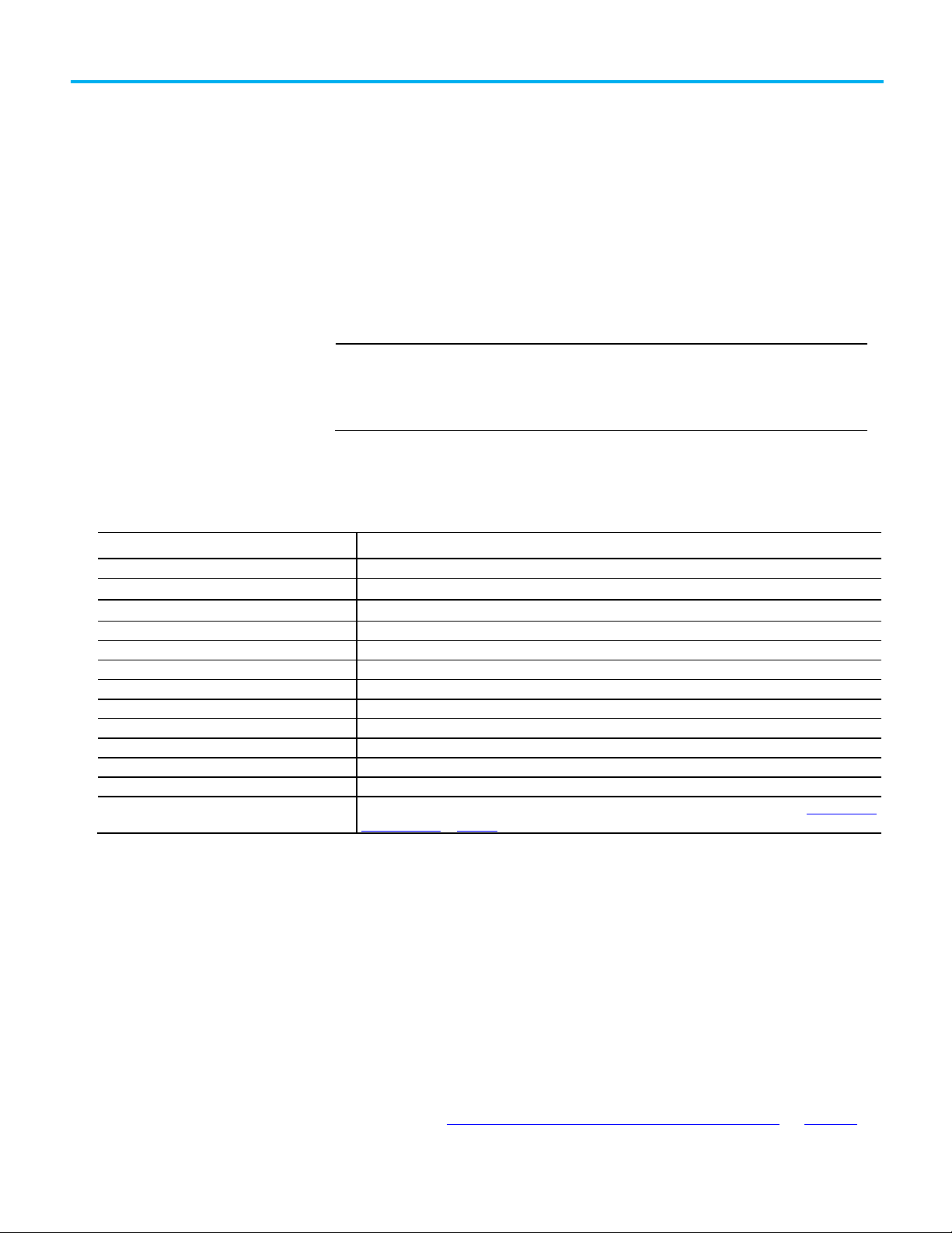
Software
Version
FactoryTalk Services Platform
2.10 or later
RSLogix 5000
16.03 or later (or the Logix Designer application version 21.00 or later)
Logix Designer
21.00 or later (or RSLogix 5000® software version 16.03 or later)
RSLogix 500
Version that supports FactoryTalk Services Platform 2.10 or later
RSLogix 5
Version that supports FactoryTalk Services Platform 2.10 or later
FactoryTalk View SE
5.00 or later
FactoryTalk View Studio
5.00 or later
RSLinx Classic (used for Logix programming)
2.50.20 or later
ControlFLASH™
4.00.09 (used to download firmware)
SoftLogix™
16.03 or later
Microsoft® SQL Server®
Version that supports FactoryTalk Alarms and Events historical logging. For more information, see Supported SQL
Server databases on page 169.
Required software
Recommended hardware
Logix 5000 controllers
What you need to get started
The FactoryTalk® System Configuration Guide describes the tasks that are
required to install, configure, and use FactoryTalk Alarms and Events services
as part of a FactoryTalk-enabled automation system. This guide also includes
references to additional documentation that provides more detail.
setting up a network station application or network distributed application is similar. This
guide provides information about the latter two applications where it is necessary. See
the Help included with the individual software products used to configure and use Alarms
T
he following software is required to configure and operate FactoryTalk
Alarms and Events services:
FactoryTalk Alarms and Events 2.10 or later (included with FactoryTalk View Site Edition and FactoryTalk® Linx™)
FactoryTalk Linx 5.00 or later
The hardware and supported operating systems that are recommended to run
and supported operating
systems
FactoryTalk Alarms and Events are the same as those recommended to run
FactoryTalk View Site Edition. For details, see the FactoryTalk View Site Edition
Installation Guide. To access the guide, in the FactoryTalk View Studio toolbar
click Help, point to Online Books, and then click Installation Guide.
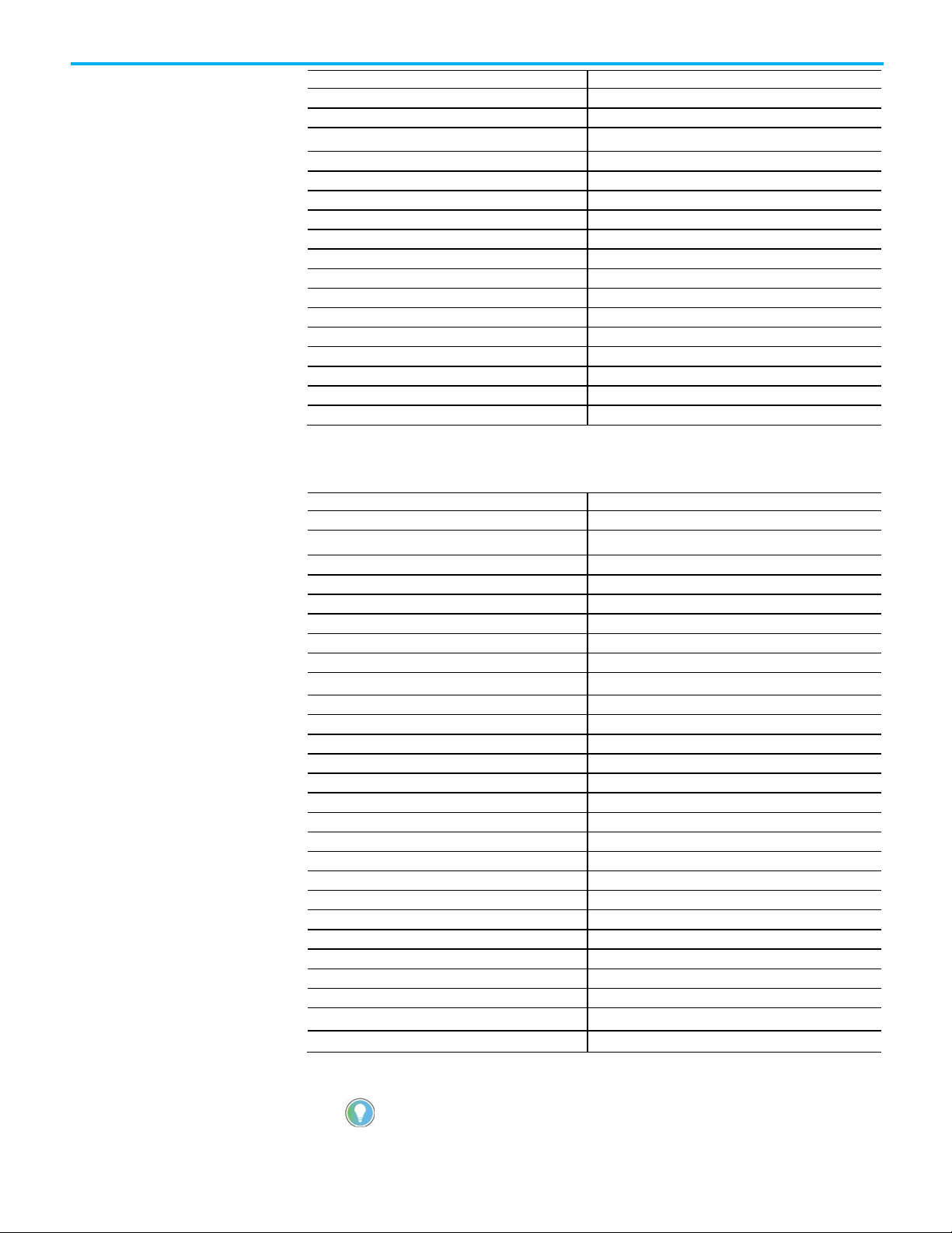
The Logix 5000 controllers listed in the following table support FactoryTalk
Alarms and Events services. When you use built-in alarm instructions in
Logix 5000 controllers, these controllers require a firmware update to revision
16.20 or later (excluding 21 to 23). If you do not want to update the firmware in
your controllers, use a Tag Alarm and Event Server for software-based alarms
and events. See Decide what type of alarm monitoring you need on page 26
.
Rockwell Automation Publication FTAE-RM001M-EN-E - March 2021
9
Page 10
Chapter 1 What you need to get started
Catalog number
Name
1756-L61
ControlLogix Processor
1756-L62
ControlLogix Processor
1756-L64
ControlLogix Processor
1756-5555
5555 ControlLogix Processor
1768-L43
CompactLogix L43 Controller
1769-L31
CompactLogix L31 Controller
1769-L32C
CompactLogix L32C Controller
1769-L32E
CompactLogix L32E Controller
1769-L35CR
CompactLogix L35CR Controller
1769-L35E
CompactLogix L35E Controller
1794-L34
FlexLogix L34 Controller
1756-L61S
ControlLogix Safety Processor
1756-L62S
ControlLogix Safety Processor
PowerFlex 700S 2
DriveLogix5370
1789-L60
SoftLogix5800
EMULATE
RSLogix Emulate 5000
Catalog number
Name
ControlLogix 1756-L71 Series B
ControlLogix Processor
ControlLogix 1756-L72 Series A
ControlLogix Processor
ControlLogix 1756-L72 Series B
ControlLogix Processor
GuardLogix 1756-L72S Series B
ControlLogix Safety Processor
ControlLogix 1756-L73 Series A
ControlLogix Processor
ControlLogix 1756-L73 Series B
ControlLogix Processor
ControlLogix 1756-L73XT Series B
ControlLogix Processor
GuardLogix 1756-L73SXT Series B
ControlLogix Safety Processor
ControlLogix 1756-L74 Series A
ControlLogix Processor
ControlLogix 1756-L74 Series B
ControlLogix Processor
ControlLogix 1756-L75 Series A
ControlLogix Processor
ControlLogix 1756-L75 Series B
ControlLogix Processor
CompactLogix 1769-L16ER-BB1B
CompactLogix L16ER-BB1B Controller
CompactLogix 1769-L18ER-BB1B
CompactLogix L18ER-BB1B Controller
CompactLogix 1769-L18ERM-BB1B
CompactLogix L18ERM-BB1B Controller
CompactLogix 1769-L24ER-QB1B
CompactLogix L24ER-QB1B Controller
CompactLogix 1769-L24ER-QBFC1B
CompactLogix L24ER-QBFC1B Controller
CompactLogix 1769-L27ERM-QBFC1B
CompactLogix L27ERM-QBFC1B Controller
CompactLogix 1769-L30ER
CompactLogix L30ER Controller
CompactLogix 1769-L30ER-NSE
CompactLogix L30ER-NSE Controller
CompactLogix 1769-L30ERM
CompactLogix L30ERM Controller
CompactLogix 1769-L33ER
CompactLogix L33ER Controller
CompactLogix 1769-L33ERM
CompactLogix L33ERM Controller
SoftLogix 1789-L60
SoftLogix5800
Tip: Firmware revisions 21 to 23 do not support the new alarms functionality.
1756-L63 ControlLogix Processor
The following controllers with firmware revision 24 and later support
FactoryTalk Alarms and Events services:
ControlLogix 1756-L71S Series B ControlLogix Safety Processor
GuardLogix 1756-L73S Series B ControlLogix Safety Processor
CompactLogix 1769-L36ERM CompactLogix L36ERM Controller
10
Rockwell Automation Publication FTAE-RM001M-EN-E - March 2021
Page 11
Chapter 1 What you need to get started
Catalog number
Name
ControlLogix 1756-L81E
ControlLogix Processor
ControlLogix 1756-L83E
ControlLogix Processor
ControlLogix 1756-L84E
ControlLogix Processor
ControlLogix 1756-L85E
ControlLogix Processor
CompactLogix 5069-L306ER
CompactLogix L306ER Controller
CompactLogix 5069-L306ERM
CompactLogix L306ERM Controller
CompactLogix 5069-L310ER
CompactLogix L310ER Controller
CompactLogix 5069-L310ERM
CompactLogix L310ERM Controller
CompactLogix 5069-L310ER-NSE
CompactLogix L306ER-NSE Controller
CompactLogix 5069-L320ER
CompactLogix L320ER Controller
CompactLogix 5069-L320ERM
CompactLogix L320ERM Controller
CompactLogix 5069-L330ER
CompactLogix L330ER Controller
CompactLogix 5069-L330ERM
CompactLogix L330ERM Controller
CompactLogix 5069-L340ERM
CompactLogix L340ERM Controller
Catalog number
Name
CompactLogix 5069-L380ERM
CompactLogix L380ERM Controller
CompactLogix 5069-L3100ERM
CompactLogix L3100ERM Controller
CompactLogix 1769-L37ERMO
CompactLogix L37ERMO Controller
GuardLogix 1769-L37ERMOS
CompactLogix Safety Processor
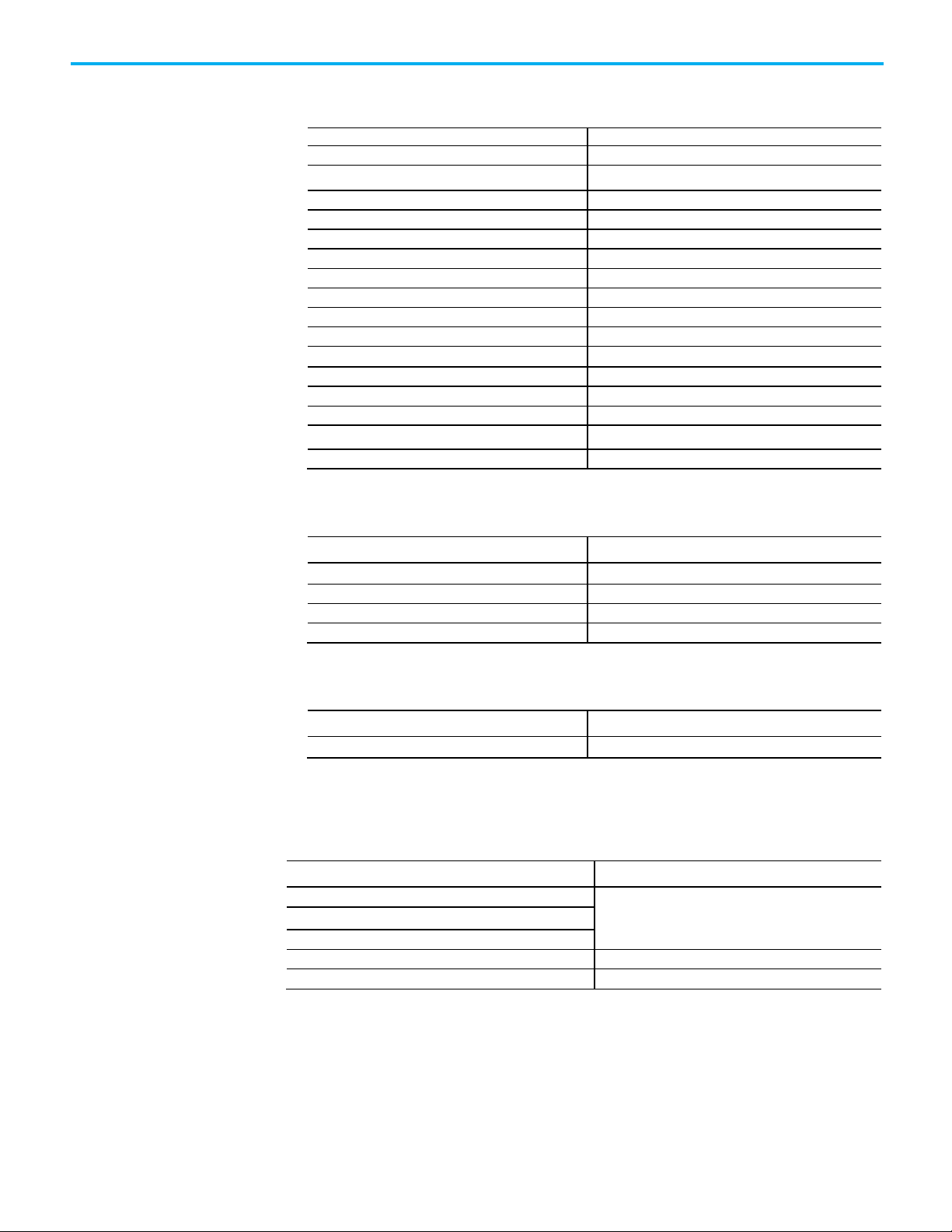
Catalog number
Name
CompactLogix 5069-L46ERMW
CompactLogix 5480 Controller
Controller
Firmware revision
ControlLogix
CompactLogix L3x and L4x
DriveLogix
ControlLogix Redundant Systems
16.60 or higher (excluding 21 to 23)
SoftLogix
16.03 or higher (excluding 21 to 23)
Compatible firmware
Older controllers
The following controllers with firmware revision 29 introduce support for
FactoryTalk Alarms and Events services:
ControlLogix 1756-L82E ControlLogix Processor
CompactLogix 5069-L340ER CompactLogix L340ER Controller
The following controllers with firmware revision 30 introduce support for
FactoryTalk Alarms and Events services:
The following controllers with firmware revision 32 introduce support for
FactoryTalk Alarms and Events services:
Automatic Diagnostics is supported only on Compact GuardLogix 5380, CompactLogix 5380, CompactLogix 5480,
ControlLogix 5580, and GuardLogix 5580 controllers, and the firmware revision must be 33 or later.
The controller firmware revisions listed in the following table are compatible
with FactoryTalk Alarms and Events services:
16.20 or higher (excluding 21 to 23)
These controllers also support FactoryTalk Alarms and Events services:
• Logix 5000 controllers that communicate with FactoryTalk Linx, using
Tag Alarm and Event Servers.
Rockwell Automation Publication FTAE-RM001M-EN-E - March 2021
11
Page 12

Chapter 1 What you need to get started
How to get the information
you need
• PLC-5® and SLC™ 500 controllers that communicate with FactoryTalk
Linx (or RSLinx Classic to bridge from Ethernet to DH+™ or DH-485
networks), using Tag Alarm and Event Servers.
• Third-party PLCs that communicate with OPC® Data Servers such as
KEPWare, using Tag Alarm and Event Servers.
For more information about the products and components discussed in this
guide, the following manuals and Help files are available:
• FactoryTalk Help
• Studio 5000 Logix Designer Help (for help with developing a controller
project)
• Studio 5000 Logix Designer Online Books
• FactoryTalk View Site Edition Installation Guide
• FactoryTalk View Site Edition User Guide
• RSLinx Classic Help (for help with configuring drivers and creating
topics)
• RSLinx Classic Quick Start Guide
• FactoryTalk Linx Getting Results Guide
• FactoryTalk Linx Help
12
Rockwell Automation Publication FTAE-RM001M-EN-E - March 2021
Page 13

Chapter 2
IMPORTANT
FactoryTalk View version 10.00 is the last release to support the legacy HMI tag alarms.
and Events.
Overview of FactoryTalk Alarms and Events
services
FactoryTalk Alarms and Events was introduced with FactoryTalk Services
Platform 2.0 (CPR 9) and FactoryTalk View Site Edition 5.0 (CPR 9) to provide
a common, consistent view of alarms and events throughout a FactoryTalk
system.
Beginning with FactoryTalk Alarms and Events 2.30 (CPR 9 SR 3), devicebased and tag-based servers support redundant server configuration.
We highly recommend that you update your alarming strategy to use FactoryTalk Alarms
FactoryTalk Alarms and Events supports two types of alarm monitoring:
• Device-based alarms, including:
• Logix instruction-based alarms
Alarm instructions are programmed and then downloaded into
Logix 5000 controllers. The controller detects alarm conditions and
publishes the alarm information, which is routed to FactoryTalk
Alarms and Events.
• Logix tag-based alarms
Logix tag-based alarms associate alarm conditions with tags for
Logix 5000 controllers. Logix tag-based alarms monitor tag values
to determine the alarm condition, but they are not part of the logic
program and do not increase the scan time for a project. Logix tagbased alarms are supported only on Compact GuardLogix 5380,
CompactLogix 5380, CompactLogix 5480, ControlLogix 5580, and
GuardLogix 5580 controllers.
• Server tag-based alarms
If you are not using Logix 5000 controllers, or if you do not want to use
the built-in alarms or alarm instructions that are available with the
Logix Designer application, server tag-based alarm monitoring offers
the equivalent of HMI tag alarm monitoring, but with an expanded
feature set. Tag Alarm and Event servers monitor controllers for alarm
conditions through data servers and publish event information that
can be displayed and logged. Server tag-based alarm monitoring is
supported for Logix 5000 controllers, PLC-5, and SLC 500 devices
communicating through Rockwell Automation device servers
Rockwell Automation Publication FTAE-RM001M-EN-E - March 2021
13
Page 14

Chapter 2 Overview of FactoryTalk Alarms and Events services
(FactoryTalk Linx), or for third-party controllers communicating
through OPC Data Servers.
FactoryTalk Alarms and Events:
• Provides a single, integrated set of alarm information.
All participating FactoryTalk products work together to provide a
consistent way to define, manage, log, and view alarm and event
information across a FactoryTalk application.
• Streamlines alarm programming and eliminates polling with devicebased alarm monitoring.
If your automation system includes Logix 5000 controllers, you can use
pre-built alarms or alarm instructions, available in the Logix Designer
application (RSLogix 5000 software version 16 or later), to simplify
coding, and then download them to the controller. Device-based alarm
monitoring eliminates the need for duplicating alarm tags in an HMI
server and requires fewer controller communication resources by
eliminating polling.
• Supports other controllers in the integrated system with server tagbased alarm monitoring.
If your automation system includes other Rockwell Automation
controllers, such as PLC-5s or SLC 500s, or if you prefer not to use the
alarms or alarm instructions with Logix 5000 controllers, softwarebased tag servers monitor controllers for alarm conditions and publish
event information.
• Monitors alarms and events from third-party controllers.
Server tag-based alarm monitoring also makes it possible to monitor
alarm conditions from third-party controllers, which communicate
through OPC Data Servers.
• Provides accurate time stamps on alarm conditions that are generated
from Logix 5000 controllers using device-based alarm monitoring.
When you use device-based alarm monitoring, timestamps are applied
immediately in the controller and are not delayed until alarms reach an
HMI server. To make sure that the timestamps on device-based alarms
are accurate, synchronize the clocks of all controllers that produce
alarms. The event time is propagated throughout the FactoryTalk
Alarms and Events system, so inaccurate timestamps can affect where
alarms are displayed in the Alarm and Event Summary or the Alarm
and Event Banner as well as reports about the alarm and event history.
For more information about synchronizing controller clocks, see
Time
synchronization on page 179.)
14
• Subscribes to and displays diagnostic events enabled by the Automatic
Diagnostics feature of Studio 5000 Logix Designer. Automatic
Diagnostics is supported only on Compact GuardLogix 5380,
CompactLogix 5380, CompactLogix 5480, ControlLogix 5580, and
Rockwell Automation Publication FTAE-RM001M-EN-E - March 2021
Page 15

Choose between HMI Tag
Alarm Monitoring and
FactoryTalk Alarms and
Events
Chapter 2 Overview of FactoryTalk Alarms and Events services
GuardLogix 5580 controllers, and the firmware revision must be 33 or
later.
• Sends process data with events and messages.
You can associate up to four tags with each alarm to include process
da
ta with event information and alarm messages.
• Secures access to alarm and event operations through integration with
FactoryTalk Security.
• Generates messages for logging.
Log messages include audit messages that track operator actions,
system-related diagnostic messages, and historical alarm and event
messages.
• Shows alarm messages and status information at runtime, in
FactoryTalk View graphic displays.
HMI tag alarm monitoring and FactoryTalk Alarms and Events are two
separate alarm monitoring systems that do not share alarm information with
each other. FactoryTalk tag-based and device-based alarm information can
only be displayed in the FactoryTalk alarm and event objects. FactoryTalk
View HMI tag alarm information cannot be displayed in FactoryTalk alarm
and event objects.
If you are already using HMI tag alarm monitoring in existing applications
you can continue using it. However, to take advantage of the new features of
FactoryTalk Alarms and Events you will need to migrate your existing alarm
monitoring system to FactoryTalk Alarms and Events.
Migrate to FactoryTalk Alarms and Events if you want to:
• Use device-based alarm monitoring. You can use a Logix 5000
controller not only to detect alarms, but also to monitor alarms. This
keeps all alarm and event processing in the controller. To use devicebased alarm monitoring, add the built-in alarm instructions, available
in the Logix Designer application (or RSLogix 5000 software version 1
o
r later), to a logic project and then download the project to a Logix
5000 controller. The controller detects alarm conditions and publishes
vent information, which can be displayed and logged.
e
• Use language-switching with alarm messages. Language switching is
not supported for alarm messages when you use HMI tag alarm
monitoring in FactoryTalk View Site Edition. FactoryTalk View
Machine Edition supports language-switching with alarm messages in
version 5.0 or later.
• Take advantage of the richer feature set offered by FactoryTalk Alarms
and Events, including:
6
• Redundant software-based Tag Alarm and Event servers that
monitor controllers for alarm conditions through data servers an
publish event information that can be displayed and logged.
Rockwell Automation Publication FTAE-RM001M-EN-E - March 2021
d
15
Page 16

Chapter 2 Overview of FactoryTalk Alarms and Events services
Where to start
FactoryTalk Alarms and
• Configurable Alarm and Event Summary that includes the ability to
suppress alarms directly from the summary, without the use of
separate commands.
• Alarm and Event Banner, Alarm and Event Log Viewer, and Alarm
Status Explorer objects that are hosted in graphic displays. You can
use the Alarm Status Explorer to enable or disable alarms, suppress
or unsuppress alarms, shelve or unshelve alarms, and view operato
co
mments.
• System-wide views in the Alarm and Event Banner, rather than just
the alarms in a single HMI server exposed by th
em\AlarmBanner system tag.
syst
Here is an overview of the sections covered in this guide:
1. Overview of FactoryTalk Alarms and Events services on page 13
2. Plan your system on page 25
• Set up device-based alarm monitoring
efine device-based alarms in Logix 5000 controllers on page 29
a. D
b. Add a device server for Logix 5000, PLC-5, or SLC 500 controllers
on page 39
r
e
Events components
• Set up tag-based alarm monitoring
dd an OPC data server for third-party controllers on page 47
a. A
b. Add a tag-based alarm server for Logix 5000, PLC-5, SLC 500, or
third-party controllers on page 51
3. Set up graphic displays on page 59
4. Monitor and interact with alarms at runtime on page 83
5. Set up historical alarm and event logging on page 101
6. Configure redundancy for alarms and events on page 119
16
Rockwell Automation Publication FTAE-RM001M-EN-E - March 2021
Page 17
Chapter 2 Overview of FactoryTalk Alarms and Events services
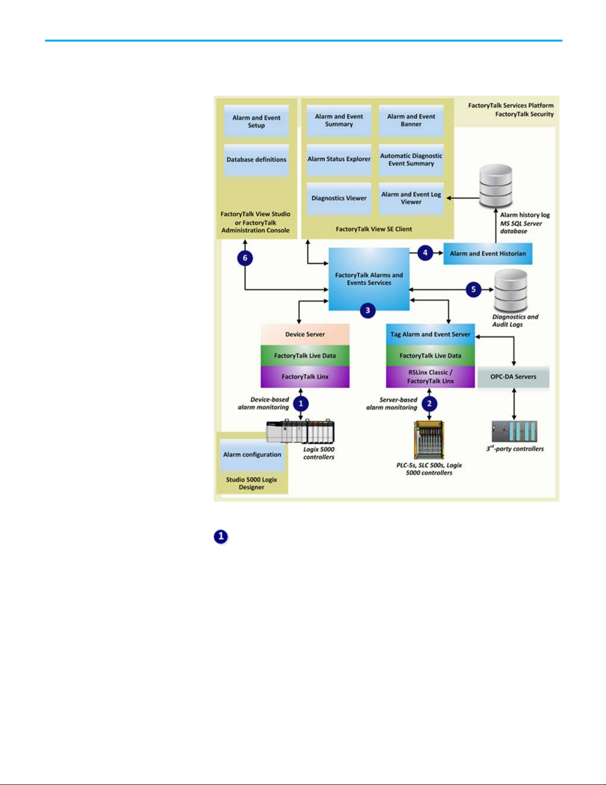
The following diagram shows a high-level view of the components of the
FactoryTalk Alarms and Events system. For more detailed information, see
FactoryTalk Alarms and Events Help.
Device-based alarm monitoring
With device-based alarm monitoring that are available with the Studio 5000
Logix Designer application, pre-built alarms or alarm instructions are
configured and then downloaded into a Logix 5000 controller. The controller
detects alarm conditions and notifies alarms and events services of alarm
states. Software components publish this information to a device server. From
the device server, the information can be logged to a database and monitored
from FactoryTalk View graphic displays.
Use device-based alarm monitoring with Logix 5000 controllers, programmed
with the Logix Designer application, communicating through Rockwell
Automation Device Servers (FactoryTalk Linx).
Rockwell Automation Publication FTAE-RM001M-EN-E - March 2021
17
Page 18

Chapter 2 Overview of FactoryTalk Alarms and Events services
Server tag-based alarm monitoring
If you are not using Logix 5000 controllers, or if you do not want to use the
pre-built alarming available with the Logix Designer application, server tagbased alarm monitoring offers the equivalent of HMI tag alarm monitoring,
but with an expanded feature set. The server tag-based Alarm and Event
servers monitor controllers for alarm conditions through data servers and
publish event information for display and logging. These data servers serve
tags, or data items, contained in OPC-DA (Data Access) servers. Clients that
need access to data items, such as FactoryTalk View Studio and FactoryTalk
Transaction Manager, use data server application elements referenced from
the FactoryTalk Directory to locate the computers that are hosting OPC-DA
2.0 compliant data servers.
Use the server tag-based alarm monitoring for Logix 5000 controllers, PLC-5
devices, and SLC 500 devices communicating through Rockwell Automation
Device Servers (FactoryTalk Linx), or for third-party controllers
communicating through OPC data servers.
FactoryTalk Alarms and Events services
Both device-based and tag-based alarms and events are published to
FactoryTalk Alarms and Events services, which then routes the information to
FactoryTalk Alarms and Events objects hosted in FactoryTalk View, the alarm
and event history log, and to diagnostic logs and audit logs.
Alarm and Event Historian
The Alarm and Event Historian is a logging component that installs silently as
part of the FactoryTalk Alarms and Events software. It manages connections
between alarm servers and databases and logs data from each alarm server to
an alarm history database. An Alarm and Event Log Viewer allows viewing and
printing data from alarm history databases. Third-party database tools can
also retrieve, view, analyze, and print alarm history information.
To use alarm and event logging, install SQL Server separately, or use an
existing SQL Server database. See the release notes for FactoryTalk Alarms
and Events for the latest qualified versions of SQL Server.
18
Diagnostic and audit logs
FactoryTalk Diagnostics routes messages generated by FactoryTalk Alarms
and Events to Local logs on the computers hosting FactoryTalk components,
and optionally to a centralized database log. Audit messages are routed to the
Rockwell Automation Publication FTAE-RM001M-EN-E - March 2021
Page 19

Chapter 2 Overview of FactoryTalk Alarms and Events services
Local log as well and to the FactoryTalk Audit Log if FactoryTalk AssetCentre is
installed.
Alarm and event setup and monitoring
These components define alarm conditions, set up alarm servers, view and
interact with alarm conditions, and view and run reports on historical alarm
information:
• Alarm and Event Banner
Use the Alarm and Event Banner object, embedded in a FactoryTalk
View graphic display, to monitor and respond to the most seriou
arms requiring immediate attention.
al
• Alarm and Event Log Viewer
Use the Alarm and Event Log Viewer object, embedded in a
FactoryTalk View graphic display, to view, filter, and print historical
alarm information stored in SQL Server databases.
s
• Alarm and Event Summary
Use the Alarm and Event Summary object, embedded in a FactoryTalk
View graphic display, to acknowledge, disable, suppress, filter, and sort
alarms during runtime.
• Alarm Status Explorer
Use the Alarm Status Explorer object, embedded in a FactoryTalk View
g
raphic display, to enable or disable alarms, suppress or unsuppress
alarms, shelve or unshelve alarms, and view operator comments.
• Automatic Diagnostic Event Summary
Use the Automatic Diagnostic Event Summary object, embedded in a
FactoryTalk View graphic display, to suppress, unsuppress, filter, and
sort diagnostic events during runtime.
• Alarm Server Setup
Use either FactoryTalk View Studio or FactoryTalk Administration
Console to add Rockwell Automation Device Servers (as part of
configuring FactoryTalk Linx data servers) and Tag Alarm and Event
ervers to a FactoryTalk application.
S
• Database definitions
Use database definitions to define logging options from an alarm
server to a SQL Server database.
• Diagnostics Viewer
Use the Diagnostics Viewer to view, filter, and export systemgenerated diagnostic messages. Run the Diagnostics Viewer from
either FactoryTalk View Studio or FactoryTalk Administration Console.
• FactoryTalk Audit Log
Rockwell Automation Publication FTAE-RM001M-EN-E - March 2021
19
Page 20
Chapter 2 Overview of FactoryTalk Alarms and Events services
About monitoring for alarm
About device-based alarm
Device-based alarm
Use the FactoryTalk Audit Log to view and manage audit messages
routed by FactoryTalk Diagnostics. To access the Audit Log, use
FactoryTalk AssetCentre software.
You can monitor for alarm conditions in either of two ways--using device-
conditions
monitoring
based alarm monitoring, or server tag-based alarm monitoring.
With device-based alarm monitoring, detection and monitoring for alarm
conditions are both done in the controller. This is in contrast to server tagbased alarm monitoring, where alarm detection occurs in the controller, but
alarm monitoring is performed by software-based servers.
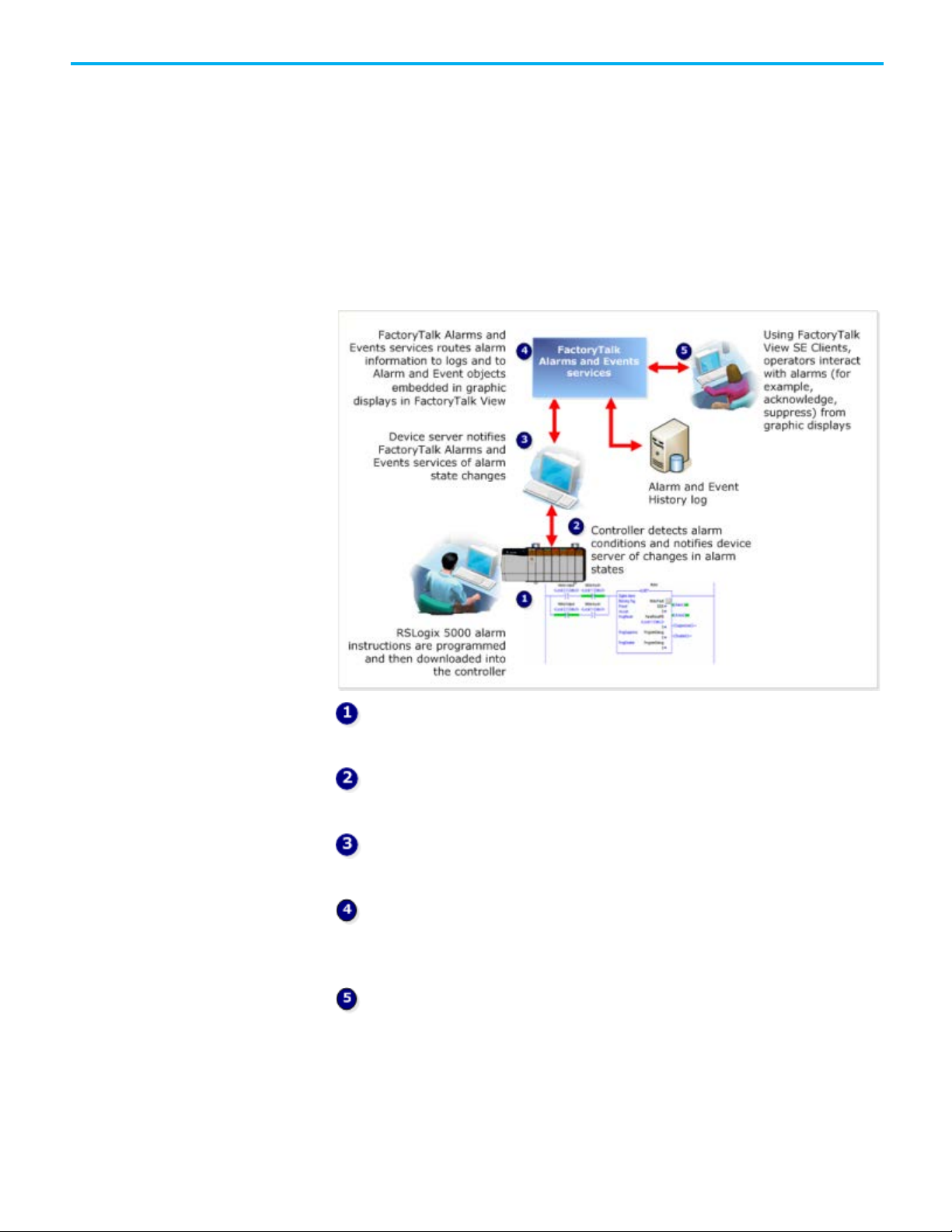
monitoring workflow
larm instructions or alarms are programmed and then downloaded
A
into a Logix 5000 controller.
The controller detects alarm conditions and notifies its device server,
FactoryTalk Linx, of alarm states.
The device server extracts alarms and publishes the information to
FactoryTalk Alarms and Events services.
FactoryTalk Alarms and Events services routes the alarm information to
logs and to Alarm and Event objects embedded in graphic displays in
FactoryTalk View.
Operators interact with alarms through objects embedded in graphic
displays, such as Alarm and Event Summary, Alarm and Event Banner, and
Alarm Status Explorer.
This approach offers a number of benefits over generic methods of alarm
detection:
20
Rockwell Automation Publication FTAE-RM001M-EN-E - March 2021
Page 21
Chapter 2 Overview of FactoryTalk Alarms and Events services
About server tag-based
Server tag-based alarm
• Alarm instructions are programmed only once, and then downloaded
the controller, reducing programming effort and errors.
to
• Alarm conditions are detected more quickly.
• Real-time alarming is performed in the controller.
• HMI tags or alarms in a Tag Alarm and Event Server are not required,
reducing overhead and potential tag-mapping errors.
• Alarm states are managed, processed, and preserved by controllers,
even if a server goes down.
• Data polling is eliminated; alarm status is communicated only when
state changes, reducing network overhead and controller processing,
and improving overall system performance.
• Time stamps on alarm conditions are more accurate, because they are
applied in the controller, and not delayed until they reach the HMI
software or Tag Alarm and Event Server. Because device-based alarms
are stamped with the controller’s time, all controllers producin
al
arms must have their clocks synchronized. The event time is
propagated throughout the FactoryTalk Alarms and Events system, so
inaccurate time stamps can affect where alarms are displayed in the
Alarm and Event Summary or the Alarm and Event Banner as well as
reports based on the alarm and event history. For more information
about synchronizing controller clocks, see Time synchronization
page 179.
g
on
alarm monitoring
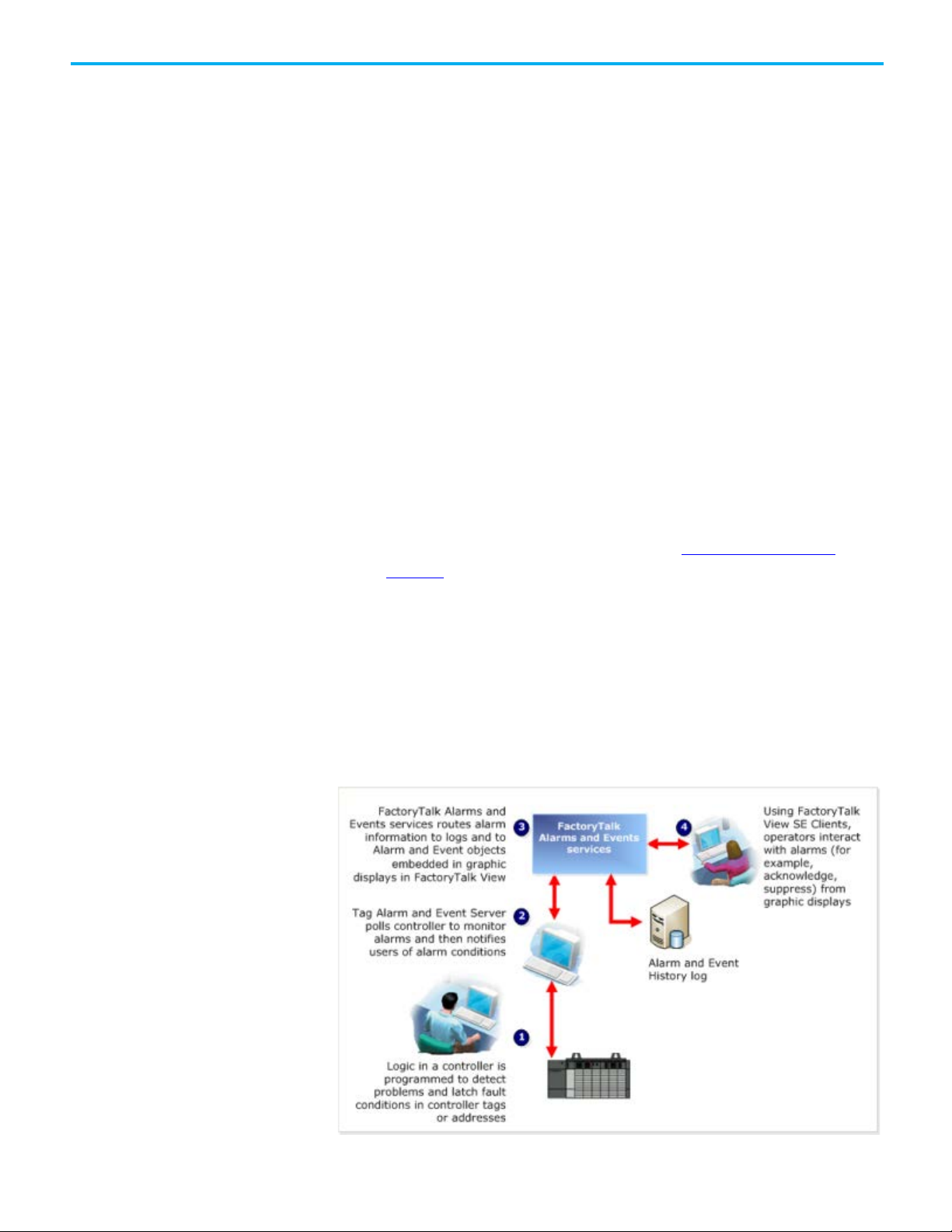
monitoring workflow
HMI tag alarm monitoring, offered by FactoryTalk View Site Edition (SE),
and tag-based alarm monitoring, offered by FactoryTalk Alarms and Events,
are both examples of software-based alarm monitoring.
Software-based alarm monitoring is a generic way of monitoring alarms from
legacy or third-party controllers.
With software-based alarm monitoring, alarm detection occurs in the
controller, but alarm monitoring is performed by software-based servers.
Rockwell Automation Publication FTAE-RM001M-EN-E - March 2021
21
Page 22

Chapter 2 Overview of FactoryTalk Alarms and Events services
Choose between device-
Logic in a controller is programmed to detect problems and latch alarm
conditions in tags.
Alarm conditions are defined through software hosted by FactoryTalk
View Studio or FactoryTalk Administration Console.
A Tag Alarm and Event Server polls controller tags and notifies clients,
including FactoryTalk Alarms and Events, of alarm conditions.
FactoryTalk Alarms and Events services routes the alarm information to
logs and to Alarm and Event objects embedded in graphic displays in
FactoryTalk View.
Using FactoryTalk View SE Clients, operators interact with alarms
(acknowledge, disable, suppress, and other commands) from graphic displays,
such as the Alarm and Event Summary, the Alarm and Event Banner, and the
Alarm Status Explorer.
This approach has several disadvantages:
based and server tag-based
alarm monitoring
• Programming is required in both the controller, and the HMI software
or Tag Alarm and Event Server.
• Tags must be duplicated in the HMI server and mapped to the
controller. For Tag Alarm and Event Servers, controller tags must be
mapped to alarms--which can be a tedious, error-prone process.
• Alarms are detected and processed twice, first in the controller logic
and then again in the HMI software or Tag Alarm and Event Server.
• Polling between the HMI server or Tag Alarm and Event Server and
controller tags increases network overhead.
• Alarm time stamps are delayed because they are applied by the HMI
server or Tag Alarm and Event Server after polling and processing,
rather than immediately when they occur. Time stamps are not
synchronized among multiple alarm servers.
• Alarm acknowledge and enable states are held in the computer, and
not in the controller. If the computer fails, alarm state information is
lost.
Use device-based alarm monitoring with:
• Logix 5000 controllers, using downloaded alarms or alarm instructions
programmed with the Logix Designer application (or RSLogix 5000
software version 16 or later)
22
Use server tag-based alarm monitoring with:
• Logix 5000 controllers
• PLC-5, SLC 500 devices
• Third-party controllers that communicate through OPC Data Servers
Rockwell Automation Publication FTAE-RM001M-EN-E - March 2021
Page 23

To do this
way
do it this way
Acknowledge, disable, suppress,
HMI Tag Alarm Summary
Alarm and Event Summary
View, filter, and print historical
HMI Tag Alarm Log Viewer
Alarm and Event Log Viewer
Graphic objects in
FactoryTalk Alarms and
Events
Chapter 2 Overview of FactoryTalk Alarms and Events services
FactoryTalk Alarms and Events graphic objects are on the Objects menu in the
graphics editor in FactoryTalk View Site Edition. The HMI tag alarm
monitoring objects remain available for compatibility with existing
applications.
filter, and sort alarms at runtime
Enable or disable alarms,
suppress or unsuppress alarms,
and view operator comments
Monitor and respond to the most
serious alarms that require
immediate attention
alarm information
In HMI tag alarm monitoring, you do it this
HMI Tag Alarm Summary (suppress only, using
the Execute feature)
SuppressOn and SuppressOff commands
Suppressed list
Alarm system tags Alarm and Event Banner
Alarms are logged to a proprietary format, and
can be exported to an ODBC-compliant
database.
With FactoryTalk Alarms and Events, you
Alarm and Event Summary (suppress only; to
unsuppress alarms, use the Alarm Status
Explorer)
Alarm Status Explorer
Historical alarm information is stored in
Microsoft SQL Server databases.
Rockwell Automation Publication FTAE-RM001M-EN-E - March 2021
23
Page 24

Page 25

IMPORTANT
FactoryTalk Alarms and Events is not supported for use with FactoryTalk View Machine
Decide what type of
application you are building
Chapter 3
Plan your system
Before you build and deploy FactoryTalk Alarms and Events as part of a local
or network application, consider which computer hardware and operating
systems you plan to use, and where to install the various hardware and
software components. The information in this chapter offers some guidelines
as you begin planning. See also Required software on page 9
Recommended hardware and supported operating systems on page 9.
You must decide whether you are building a local station application or
network station application on a stand-alone computer, or a network
distributed application distributed across multiple computers. This system
configuration guide primarily discusses how to install, configure, and use
software on a stand-alone system.
and
Edition.
• Network distributed applications are held in a FactoryTalk Network
Directory. Participating software products can be located on multiple
computers, distributed across a network. All of the computers
participating in a particular network distributed application share
common Network Directory Server located on a network computer.
See Typical distributed system on a network on page 189
graphical overview.
The application you create in the Network Directory can be divided
into any number of areas. Each area can contain one or more sub-areas
and one or more data servers. Each area or sub-area can contain only
one HMI server. A network distributed application supports
FactoryTalk Alarms and Events redundancy.
• Network station applications are held in a FactoryTalk Network
Directory. All participating software products (except for data servers)
must be installed on the same computer. Network station applications
can connect to data servers that are located on different machines. All
of the computers participating in a particular network station
application share a common Network Directory Server located on a
network computer. See Typical stand-alone system on page 27
graphical overview.
for a
for a
a
The application you create in the Network Directory can be divided
into any number of areas. Each area can contain one or more sub-areas
and one or more data servers. A network station application consists of
only one HMI server. You can add the HMI server in the root area or
Rockwell Automation Publication FTAE-RM001M-EN-E - March 2021
25
Page 26

Chapter 3 Plan your system
IMPORTANT
To use FactoryTalk Alarms and Events with a local station application, install all
applications and network distributed applications.
Tip: FactoryTalk Services Platform and FactoryTalk Alarms and Events software is installed
along with FactoryTalk View and FactoryTalk Linx software.
Decide what type of alarm
Follow these steps
within the areas you have created. A network station application
supports FactoryTalk Alarms and Events redundancy.
monitoring you need
• Local station applications are suitable for self-contained, stand-alon
rocesses that do not interact with other processes or systems. Local
p
station applications are held in a FactoryTalk Local Directory and are
accessible only from the local computer where they reside. Even if th
c
omputer is connected to a network and even if a network applicatio
esides on the same computer, the applications you create in the
r
FactoryTalk Local Directory remain self-contained and do not share
data or project elements.
Local station applications do not support areas, and all application
components and participating software products are located on a
single computer. See Typical stand-alone system on page 27
for a
graphical overview.
software on the same computer.
FactoryTalk Alarms and Events redundancy is only supported in network station
actoryTalk Alarms and Events supports two types of alarm monitoring:
F
• Device-based alarm monitoring
Built-in alarms or alarm instructions, that are available in the Logix
Designer application (RSLogix 5000 software version 16 or later), are
programmed in a logic project and then downloaded to a Logix 5000
controller. The controller detects alarm conditions and publishes event
information, which can be displayed and logged.
e
e
n
• Server tag-based alarm monitoring
Software-based tag alarm and event servers monitor controllers for
alarm conditions through data servers and publish event information,
which can be displayed and logged. Tag-based alarm monitoring is
supported for Logix 5000, PLC-5, and SLC 500 devices communicating
through Rockwell Automation device servers (FactoryTalk Linx), or for
third-party controllers that communicate through OPC Data Servers.
You can use a mix of both types of alarm monitoring. Choose server tag-based
alarm monitoring if you do not want to change the logic in your
programmable controllers, or if you do not want to update the firmware in
Logix 5000 controllers.
Follow these steps to plan your system:
• Determine network configuration
• Install and activate FactoryTalk View software
• Install FactoryTalk Linx software
26
Rockwell Automation Publication FTAE-RM001M-EN-E - March 2021
Page 27
IMPORTANT
This guide describes how to set up a local station application. The procedure to set up a
Reference for building a distributed system on page 189.
What you need
Install and activate
FactoryTalk software
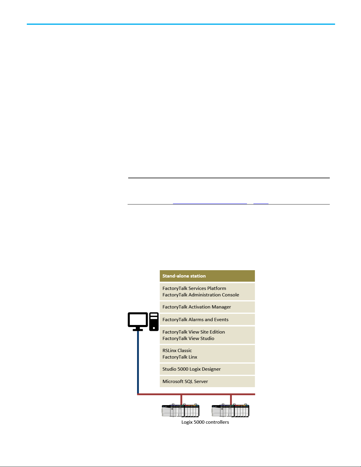
Typical stand-alone system
Chapter 3 Plan your system
• Install RSLinx Classic software
• Install and activate RSLogix software
• Update Logix 5000 firmware to V16 or later (optional if using Ta
Al
arm and Event Servers)
• (optional) Install Microsoft SQL Server 2014 SP3 Express
• Decide what type of application you are building.
• Decide what type of alarm monitoring you need.
• Install and activate FactoryTalk software.
• Update Logix 5000 firmware to revision 16.20 or later (excluding 21 to
23), if you plan to use device-based alarm monitoring and alarm
instructions that are built into Logix 5000 controllers. If you do no
lan to use device-based alarm instructions, you can skip this step and
p
use tag-based alarm monitoring with a Tag Alarm and Event Server
instead.
Follow these procedures to install and activate the software products required
for FactoryTalk Alarms and Events.
network station application or network distributed application is similar. This guide
provides additional information about the two applications where it is necessary. See also
g
t
For more information about each software product, see its respective product
Help.
To use FactoryTalk Alarms and Events with a local station application or a
network station application as part of a stand-alone FactoryTalk system,
install all software on the same computer. Use this diagram only as a starting
point--your own system will vary.
Rockwell Automation Publication FTAE-RM001M-EN-E - March 2021
27
Page 28

Chapter 3 Plan your system
IMPORTANT
This guide provides additional information about network distributed applications
Tip: To take advantage of the new alarms functionality in the v24 firmware, we recommend you
revision 24 or later.
Tip: If you already have Microsoft SQL Server installed, you may need to change the configuration
SQL Server database on page 169.
Install FactoryTalk software
Install Microsoft SQL Server
For specific installation instructions, refer to the installation guide for each
product.
• To develop or run local station applications, install all the necessary
software components on one computer.
• To develop or run network station applications, install all the necessary
software components (except for data servers) on one computer.
Network station applications can connect to data servers that are
located on different machines.
• To develop or run network distributed applications, install different
ombinations of software on each computer, depending on you
c
n
eeds. For more information, see FactoryTalk Help. Click Start > All
r
Programs > Rockwell Software > FactoryTalk Tools > FactoryTalk
Help.
or network station applications where it is necessary.
To set up a FactoryTalk system, install the following software:
• FactoryTalk Services Platform
• FactoryTalk Activation
• FactoryTalk View Site Edition
• FactoryTalk Linx
• RSLinx Classic
• The Studio 5000 Logix Designer application (known previously a
s
RSLogix 5000 software)
• Update Logix 5000 firmware to revision 16.20 or later (excluding 21 to
23). If you plan to use device-based alarm monitoring see
Decide what
type of alarm monitoring you need on page 26.
I
f you plan to log historical alarm and event messages to a database, you must
install Microsoft SQL Server software on the computer you want to use for
logging. If you do not have Microsoft SQL Server software installed, see
Microsoft SQL Server 2014 SP2 Express on page 165.
options to log alarm and event messages. For configuration instructions, see Use an existing Microsoft
28
Rockwell Automation Publication FTAE-RM001M-EN-E - March 2021
install FactoryTalk Services Platform v2.71 or later and update your controller firmware to
Install
Page 29

Chapter 4
Tip: Logix tag-based alarms are supported only on Compact GuardLogix 5380, CompactLogix 5380,
CompactLogix 5480, ControlLogix 5580, and GuardLogix 5580 controllers.
Tip: If your FactoryTalk application does not include Logix 5000 controllers, or if your controllers are not
a tag-based alarm server for Logix 5000, PLC-5, SLC 500, or third-party controllers on page 51.
Alarm buffering during loss
Define device-based alarms in Logix 5000
controllers
To set up device-based alarm monitoring, you program alarms or alarm
instructions that are available with the Logix Designer application (RSLogix
5000 software version 16 or later), and download them to a Logix 5000
controller. The controller detects alarm conditions and notifies alarms and
events services of alarm states. Software components publish this information
to a device server, where it can be logged to a database, and interacted from
FactoryTalk View graphic displays.
FactoryTalk Alarms and Events can handle many different types of alarms.
The controller limits the alarms to Logix tag-based alarms and instructionbased alarms. The instruction-based alarms include digital and analog alarms.
An analog alarm instruction monitors two types of alarm conditions: Level
and Rate of Change. A server tag-based alarm supports three alarm types:
Digital, Level, and Deviation.
of connection to the
controller
Logix tag-based alarms associate alarm conditions with tags for Logix 5000
controllers. Logix tag-based alarms monitor tag values to determine the alarm
condition, but they are not part of the logic program and do not increase the
scan time for a project.
A digital alarm instruction is based on the input rung state (in ladder logic) or
on the alarm input (for function block). The trigger condition compares the
value of the tag to either zero or one.
An analog alarm defines a condition that evaluates a single analog tag against
up to four limit values (high-high to low-low) and up to two rate of change
limits (positive and negative).
programmed with the alarm instructions included in the Logix Designer application (RSLogix 5000
software version 16 or later), see Add an OPC Data Server for third-party controllers on page 47 and Add
To receive device-based alarms, the alarm server (FactoryTalk Linx)
establishes a subscription to the alarms in the Logix controller. The controller
maintains a connection to each subscriber and monitors the status of that
connection.
Rockwell Automation Publication FTAE-RM001M-EN-E - March 2021
29
Page 30

Chapter 4 Define device-based alarms in Logix 5000 controllers
IMPORTANT
Firmware revision 21 to revision 23 do not support the new alarms functionality. The
buffering time unless instructed by Technical Support.
Tip: To take advantage of the new alarms functionality in the revision 24 firmware, we
your controller firmware to revision 24 or later.
Before you begin
What you need
Follow these steps
As alarm state changes occur, the controller caches information such as
timestamps, alarm state and associated tag values, and transmits the
information to all of the subscribers.
If any subscriber fails to confirm the receipt of the alarm information, or if the
connection to a subscriber is not good, the controller stores the undelivered
alarm information in a 100 KB buffer. Each subscriber has its own buffer and
communication problems with one subscriber do not interfere with alarm
delivery to other subscribers. When the buffer is full, newer alarm
information is discarded and a FactoryTalk Diagnostics message is logged.
The buffer is created when the subscriber establishes its initial connection,
and is maintained for a length of time after a subscriber loses its connection.
The length of time is specified in the Buffer Timeout setting on each
FactoryTalk Linx device shortcut. See step 3, "Create a new shortcut to the
controller," in Add a device server on page 39
.
buffer timeout setting is not available to controllers with firmware revision 24 or later. For
controllers with version 20 or earlier, we recommend that you do not change the default
• Rev
iew Plan your system on page 25
.
• Verify that you have installed and activated the software listed in the
next section under What you need on page 30
.
• Verify that the Logix 5000 firmware has been updated to revision 16 or
later (excluding revisions 21 to 23).
recommend you install FactoryTalk Services Platform software version 2.71 or later, and update
• L
ogix Designer application (RSLogix 5000 software)
• ControlFLASH
• RSLinx Classic
Follow these steps to define a digital or analog alarm:
• Plan your system
• Run Studio 5000 Logix Designer software
• Create a project
• For a digital alarm, define a boolean tag or a rung state on which to
alarm
For an analog alarm, define a analog tag on which to alarm
• Add a digital or analog alarm instruction
• Configure the digital or analog alarm properties
• Downland the project to the controller
• Test the alarm instruction
• Add a device server
• Add a data server
30
Rockwell Automation Publication FTAE-RM001M-EN-E - March 2021
Page 31

Define a Logix tag-based
alarm
Create an alarm definition
Chapter 4 Define device-based alarms in Logix 5000 controllers
Use Logix tag-based alarms to send alerts about specific events or conditions.
Logix tag-based alarms are similar to instruction-based alarms that are
created using alarm instructions (ALMA and ALMD), but Logix tag-based
alarms do not affect the scan time of the project.
Tip: Logix tag-based alarms are supported only on Compact GuardLogix 5380, CompactLogix 5380,
CompactLogix 5480, ControlLogix 5580, and GuardLogix 5580 controllers.
To define a Logix tag-based alarm:
1. On the Controller Organizer, expand the Alarm Manager folder, right-
click Alarms, and select New Alarm.
To create an alarm in Tag Editor or in the Ladder, Sequential Function
Chart, Function Block, or Structured Text editors, right-click a tag an
s
elect Add Alarm for [tag].
2. In the Name box, enter a name for the alarm.
3. In the Input box, add the input tag for the alarm. If you launch the
New Alarm dialog box from a logic editor, the Input box is populate
w
ith the tag that you right-clicked.
4. To enable the alarm, select the Required to be used and evaluated
check box. All new alarms are disabled by default.
5. Adjust other alarm settings as necessary.
d
d
An alarm definition is associated with an Add-On Instruction (AOI) or a
defined data type. When a tag is created using a data type or an AOI that has
alarm definitions, alarms are created automatically based on the alarm
definitions.
You can create an alarm definition for the following components:
• Any scalar tag or parameter of an AOI.
• Any scalar member of a user-defined data type (UDT).
• Any scalar member of a system-defined data type (SDT).
• Any scalar member of a module-defined data type (MOT).
When a tag uses a data type that has alarm definitions associated with it,
alarm conditions are automatically added for the tag based on its alarm
definitions.
When an AOI is based on an AOI definition, alarm conditions are
automatically added for the AOI instance based on the alarm definitions
associated with the AOI definition.
To create an alarm definition:
1. On the Controller Organizer, expand the Alarm Manager folder, rightclick Alarm Definitions, and select New Alarm Definition
Rockwell Automation Publication FTAE-RM001M-EN-E - March 2021
.
31
Page 32

Chapter 4 Define device-based alarms in Logix 5000 controllers
Tip: If your FactoryTalk application does not include Logix 5000 controllers, or if your controllers
third-party controllers on page 51.
Download the program to
Define an instruction-based
Configure the digital alarm
You can also right-click a scalar tag or parameter of an AOI or a scalar
member of a data type and select Add Alarm Definition.
2. In the Name box, enter a name for the alarm definition.
3. When creating an alarm definition for a UDT or AOI, in the Input box,
add an input tag. When creating an alarm definition for a data type
dd a data type member in the Input box.
a
4. To enable all instances of the alarm, select the Required to be used and
evaluated check box. All new alarms definitions are disabled by
default.
5. Adjust other settings as necessary.
You can download the program containing the Logix tag-based alarm to the
controller and test the alarm
controller and then use FactoryTalk View to test the alarm.
1. If it is not already running, start RSLinx Classic to establish
communications between the controller and the Logix Designer
application (RSLogix 5000 software version 16 or later).
2. On the Logix Designer application menu, click Communications >
Who Active.
3. Select the controller to which you want to download the project.
4. Click Download. At the prompt, click Download again. The controller
is placed in Program mode.
5. To switch the controller to run mode, click Communications > Run
Mode.
6. To test the alarm, in FactoryTalk View Studio, create a FactoryTalk
Alarms and Events graphic object (for example, Alarm and Even
ummary) to read Logix tag-based alarms with the fully qualified
S
name.
,
t
Digital tags are either on or off. They have states instead of limits. The alarm
alarm: digital
and download to the
controller
trigger condition compares the value of the tag to the configured alarm state.
An alarm can be triggered if the digital alarm is in one of these two states:
• The rung evaluation or input tag is equal to zero
• The rung evaluation or input tag is not equal to zero
This example uses the ladder logic editor that comes with the Logix Designer
application (RSLogix 5000 software) to define a digital alarm. You can also
configure digital alarms in function blocks or structured text.
Step 1. Create a rung of logic that will trigger the alarm
1. Create a new project with default settings. In this example, we use
32
Rockwell Automation Publication FTAE-RM001M-EN-E - March 2021
West_Plant_Controller.
are not programmed with the alarm instructions included in the Logix Designer application
(RSLogix 5000 software version 16 or later), see Add an OPC Data Server for third-party
controllers on page 47 and Add a tag-based alarm server for Logix 5000, PLC-5, SLC 500, or
Page 33

Chapter 4 Define device-based alarms in Logix 5000 controllers
2. In the left pane, expand the folders Tasks > MainTask > MainProgram,
nd then double-click MainRoutine.
a
3. On the Language Element toolbar, click the Examine-on instructio
button to add it to a rung on the ladder project.
4. At the top of the Examine-on instruction, click the question mark to
select it. On the File menu, click New Component, and then click Tag.
5. In the New Tag dialog box, type a name for the tag, choose BOOL a
e data type, and then click Create.
th
In our example, we name the tag alarm_active.
Step 2. Add a digital alarm instruction to the rung
1. On the Language Element toolbar, click the Alarms tab, and then click
e ALMD button . The instruction block is placed in the ladder
th
logic.
2. Inside the alarm instruction, beside ALMD, select the question mark.
3. On the File menu, click New Component, and then click Tag.
4. In the dialog box that opens, type a name for the digital alarm tag, an
then click Create.
n
s
d
In our example, we named the tag DigitalAlarm1.
Step 3. Specify a tag for each of the digital alarm's operands,
or just enter 0
1. Inside the alarm instruction, select the ProgAck operand.
2. On the File menu, click New Component, and then click Tag.
3. In the New Tag dialog box, type a name for the tag, select BOOL as the
data type, and then click Create.
In our example, we named the tag DigitalAlarm1_Ack. For details
about using the New Tag dialog box, click Help.
Rockwell Automation Publication FTAE-RM001M-EN-E - March 2021
33
Page 34

Chapter 4 Define device-based alarms in Logix 5000 controllers
Tip: To create a text message with embedded variables for each alarm, click the Message box
the character limit.
4. Create tags for the ProgReset, ProgDisable, and ProgEnable operands.
When you are finished, the alarm instruction should resemble the one
shown here:
Step 4. Configure the properties of the new digital alarm tag
1. Inside the alarm instruction, click the Browse button (...).
2. In the ALMD Properties dialog box, specify configuration settings, an
hen click OK. For help with specifying configuration settings, click
t
Help.
Browse button (...). At runtime, these messages appear in Alarm and Event graphic objects,
such as the Alarm and Event Summary. The maximum length of an alarm message is 255
characters. When importing alarm messages, the Logix Designer application (or RSLogix 5000
software) will verify the message length and display a warning if the alarm message exceeds
Step 5. Download the program containing the ladder logic to the
controller
1. If it is not already running, start RSLinx Classic to establish
communications between the controller and the Logix Designer
application (RSLogix 5000 software version 16 or later).
2. On the Logix Designer application menu, click Communications >
Who Active.
3. Select the controller to which you want to download the project.
4. Click Download. At the prompt, click Download again. The controller
is placed in Program mode.
d
34
Rockwell Automation Publication FTAE-RM001M-EN-E - March 2021
Page 35

Chapter 4 Define device-based alarms in Logix 5000 controllers
Step 6. Test the alarm instruction by switching to run mode and
triggering the alarm
1. On the Logix Designer application menu, click Communications > Run
Mode. Click Yes to switch the controller to run mode.
2. T
o trigger the alarm, right-click the contact on the rung (the one
named alarm_active), and then click Toggle Bit. The contact shoul
change from a blue highlight to a green highlight.
d
Rockwell Automation Publication FTAE-RM001M-EN-E - March 2021
35
Page 36

Chapter 4 Define device-based alarms in Logix 5000 controllers
Tip: If your FactoryTalk application does not include Logix 5000 controllers, or if your controllers are not
a tag-based alarm server for Logix 5000, PLC-5, SLC 500, or third-party controllers on page 51.
Define an instruction-based
Configure the analog alarm
Step 7. Finish creating alarms, and next steps
• Define additional digital alarms or analog alarms, using either ladder
logic, function blocks, or structured text, and download the logic to the
controller.
• When you finish defining alarms, create a device-based alarm server,
nd then configure it to subscribe to events detected by the Logix 5000
a
controller. See
controllers on page 39 for instructions.
An analog alarm defines a condition that evaluates a single analog tag against
alarm: analog
and download it to the
controller
up to four limit values (high-high, hi, low, and low-low) and up to two rate of
change limits (positive and negative).
programmed with the alarm instructions included in the Logix Designer application (RSLogix 5000
software version 16 or later), see Add an OPC Data Server for third-party controllers on page 47 and Add
This example uses the Function Block editor that comes with the Logix
Designer application (RSLogix 5000 software). You can also configure analog
alarms in ladder logic or structured text.
Add a device server for Logix 5000, PLC-5, or SLC 500
Step 1. Define a new routine
1. Create a new project with default settings. In this example, we use
East_Plant_Controller.
2. Expand the Tasks folder in the left pane, right-click MainProgram
cl
ick Add, and then click New Routine.
3. In the New Routine dialog box, type a name for the routine. We use
alarm_active.
4. In the Type list, click Function Block Diagram.
5. Select the Open Routine check box, and then click OK. The new routine
appears in the Tasks folder under MainRoutine and the routine opens
on the right side of the Logix Designer window.
Step 2. Build the function block logic
1. To add an alarm block, go to the tabs in the center right area (Favorites,
A
dd-On, and so on) as shown in the following illustration. Scroll to the
right, and then click the Alarms tab.
2. On the toolbar, click the ALMA butto
block.
3. Using the same Alarm objects on the Language Element toolbar, click
n to
add an Analog Alarm
,
the Input Reference icon .
4. Right-click the single question mark inside the symbol and then clic
Ne
w Tag.
36
Rockwell Automation Publication FTAE-RM001M-EN-E - March 2021
k
Page 37

Chapter 4 Define device-based alarms in Logix 5000 controllers
and Event graphic objects such as the Alarm and Event Summary.
5. In the New Tag dialog box, type a name for the tag and then click
Create.
In this example, we use AnalogAlarm1. The screen should resemble th
e shown in the following illustration:
on
e
. Connect the input reference block to the Input of the ALMA block, as
6
shown in the following illustration, by dragging the block's contac
p
oint to the contact point on the ALMA block.
Step 3. Configure the properties of the alarm block
1. Click the Browse button (...) on the alarm block.
2. In the ALMA Properties dialog box, set the Input Levels as shown in
the following illustration and then click OK. To require that an
operator acknowledge the alarm at runtime, make sure the
Acknowledgement Required check box is selected.
Tip: To enter alarm messages and add variables for analog alarms, select the Messages tab. To
create a text message with embedded variables, click the Browse button (...) beside the Level
field, or beside the Rate of Change field. At runtime, alarm messages are displayed in Alarm
Rockwell Automation Publication FTAE-RM001M-EN-E - March 2021
t
37
Page 38

Chapter 4 Define device-based alarms in Logix 5000 controllers
Step 4. Add a JSR instruction to the MainRoutine to run the function
block
1. Double-click MainRoutine to open it.
2. Right-click the first rung and then click Add Ladder Element.
3. In the Add Ladder Element dialog box, scroll down to the Program
Control folder and then double-click the folder to expand the list of
ntrols.
co
4. Select JSR and then click OK.
5. In the JSR instruction, double-click Routine Name and then clic
alarm_active.
6. On the toolbar, click the Save button to save the configuration.
Step 5. Download the program to the controller
1. If it is not already running, start RSLinx Classic to establish
communications between the controller and the Logix Designer
application (RSLogix 5000 software version 16 or later).
2. On the Logix Designer application menu, click Communications >
Who Active.
3. Select the controller to which you want to download the project.
4. Click Download. At the prompt, click Download again. The controller
is placed in Program mode.
5. To switch the controller to run mode, click Communications > Run
Mode.
k
Step 6. Finish creating alarms, and next steps
• Define additional digital alarms or analog alarms using either ladder
logic, function block, or structured text, and download the logic to the
controller.
• When you finish defining alarms, create a device-based alarm server
and then configure it to subscribe to events detected by the Logix 5000
controller. See
controllers on page 39.
Add a device server for Logix 5000, PLC-5, or SLC 500
,
38
Rockwell Automation Publication FTAE-RM001M-EN-E - March 2021
Page 39

Chapter 5
Tip: This guide uses FactoryTalk View Studio to define a device server. You can also use
Console menu bar, select Help > Contents.
IMPORTANT
If you are using third-party controllers, you do not need a device-based alarm server.
Before you begin
What you need
Follow these steps
Add a device server
Add a device server for Logix 5000, PLC-5, or SLC
500 controllers
Add a device server to your application to use:
• Device-based alarms in Logix 5000 controllers.
• Tag-based alarms in PLC-5, SLC 500, or Logix 5000 controllers.
• If you are using device-based alarms, define your alarms, as described
in Define device-based alarms in Logix 5000 controllers on page 29
• If you are using tag-based alarms, you create a controller program to
detect alarm conditions, and then associate those conditions with tags
that are monitored by the FactoryTalk Tag Alarm and Event Server.
• FactoryTalk Linx
• FactoryTalk View Studio or FactoryTalk Administration Console
.
FactoryTalk Administration Console. For more information, in the FactoryTalk Administration
ollow these steps to add a device server:
F
• Define alarms
• Start FactoryTalk View Studio and open a Site Edition local application
• Add a new device server
• Configure the device server properties
• Open the Communication Setup editor
• Create a new shortcut to the Logix 5000 controller and configure
settings
• Set up graphic displays
• Set up historical alarm and event logging
In this section, you will create a Rockwell Automation device server
(FactoryTalk Linx) and then configure it to subscribe to alarms that will be
detected by a Logix 5000 controller.
Instead, go to Add an OPC Data Server for third-party controllers on page 47.
Step 1. Create an application in FactoryTalk View Studio
This example shows how to create a local station application.
Rockwell Automation Publication FTAE-RM001M-EN-E - March 2021
39
Page 40

Chapter 5 Add a device server for Logix 5000, PLC-5, or SLC 500 controllers
IMPORTANT
FactoryTalk Alarms and Events is not supported for use with FactoryTalk View
1. To start FactoryTalk View Studio, click Start > All Programs > Rockwell
Software > FactoryTalk View > FactoryTalk View Studio.
2. In the Application Type Selection window, select View Site Edition
(Local Station) and then click Continue.
Machine Edition.
3. In the New/Open Site Edition (Local Station) Application dialog box,
cl
ick the New tab.
4. In the Application name field, type a name for the new local station
application. In this example, we name the application My Local Site.
5. Leave the Description field blank, or type a description for the
application. For example, you can use this field to record revisions to
the application, or contact information for technical support.
6. If it is not already selected, select the default language for the
application. This is the language in which you are creating the
application.
7. Click Create.
8. In the Add Controller Instruction Faceplates dialog box, click Clear All
and then click OK.
40
Rockwell Automation Publication FTAE-RM001M-EN-E - March 2021
Page 41
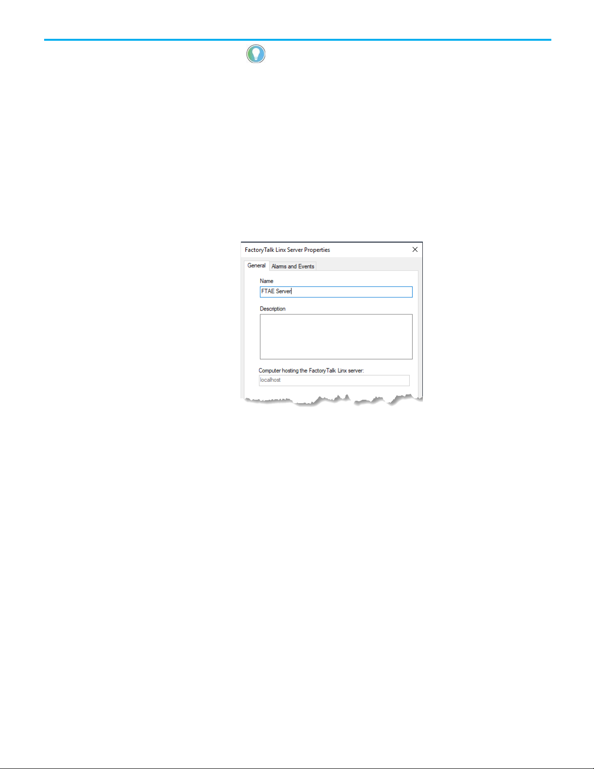
Chapter 5 Add a device server for Logix 5000, PLC-5, or SLC 500 controllers
Tip: If you have cleared the Display this dialog when creating a new application check box,
Instruction Faceplates.
the Add Controller Instruction Faceplates dialog box does not open automatically. To open it
manually, in the Explorer window right-click the HMI server, and then select Add Controller
Step 2. Configure the device server
1. In the Explorer window, right-click the new application My Local Site,
oint to Add New Server, and then click Rockwell Automation Device
p
Server (FactoryTalk Linx).
2. In the FactoryTalk Linx Server Properties dialog box, click the General
tab, type a name for the new server, and then click Apply. In this
example, we name the server FTAE Server. Leave this dialog box open
for the moment.
o one of the following:
3. D
• If you plan to use tag-based alarms, you can skip the rest of the step
in this section, and go on to the next major step: "Step 3. Create a
new shortcut to the controller." Click OK to close the FactoryTalk
Linx Server Properties dialog box
• I
f you are using built-in alarm instructions in Logix 50
.
00
controllers, continue with the steps in this section.
s
Rockwell Automation Publication FTAE-RM001M-EN-E - March 2021
41
Page 42

Chapter 5 Add a device server for Logix 5000, PLC-5, or SLC 500 controllers
4. On the Alarms and Events tab, select the Enable alarm and event
support check box.
5. Clear the Enable history check box and then click OK. For information
about historical logging, see Set up historical alarm and event logging
on page 101.
The new server is added to the My Local Site application:
42
Rockwell Automation Publication FTAE-RM001M-EN-E - March 2021
Page 43

Chapter 5 Add a device server for Logix 5000, PLC-5, or SLC 500 controllers
Step 3. Create a new shortcut to the controller
1. In the Explorer window, double-click the new FactoryTalk Linx server
and then double-click Communication Setup.
the Communication Setup dialog box, click the Add button, an
2. In
th
en type a name for the new shortcut. We use FTAE_Controller.
S
ome options in this dialog box might be different if you are using
PLC-5 or SLC 500 controllers.
The warning icon beside the OK button indicates that changing values
in this dialog box at runtime can cause unexpected results. For details,
click Help.
d
Rockwell Automation Publication FTAE-RM001M-EN-E - March 2021
43
Page 44
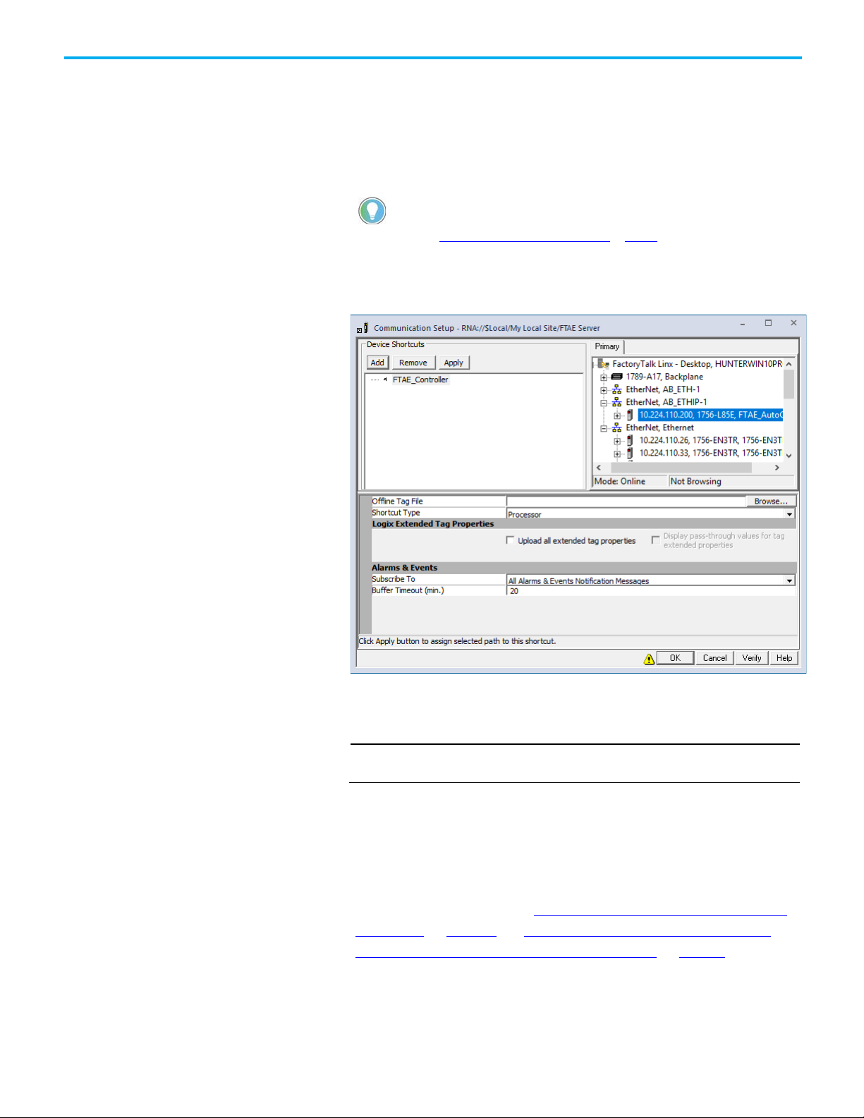
Chapter 5 Add a device server for Logix 5000, PLC-5, or SLC 500 controllers
IMPORTANT
3. Skip this step if you do not plan to use Logix 5000 controllers with
built-in alarm instructions. In the Subscribe to list, click All Alarms &
Events Notification Messages or Only Alarms Notification Messages
to enable Alarms and Events.
If you do not see the Subscribe to list, then Enable alarm and event
support was not selected in the previous step 4.
Tip: Set Buffer Timeout (min.) for the length of time (zero to 120) you want to cache alarm
information if the connection to the controller is lost. To disable alarm buffering, set the value to
zero. See Alarm Buffering during loss of connection on page 29.
4. On the Primary tab, expand the list of networks and devices until the
controller you plan to use is visible, and then click the controller.
44
5. T
o set the path to the primary controller, click the Apply button.
6. To save the shortcut configuration and close the Communication
Setup dialog box, click OK.
FactoryTalk Alarms and Events server redundancy is only supported in network
station applications and network distributed applications.
Step 4. Finish creating data servers, and next steps
1. If your FactoryTalk application includes third-party OPC-DA
c
ontrollers, add an OPC Data Server, create a tag-based alarm server,
and then define alarms. See
controllers on page 47 and Add a tag-based alarm server for Logix
5000, PLC-5, SLC 500, or third-party controllers on page 51.
2. If your FactoryTalk application is communicating with PLC-5 or SLC
00 controllers, or Logix 5000 controllers that are not using built-in
5
alarm instructions, you must add a device server (FactoryTalk Linx) to
your application and then create a tag-based alarm server and define
Rockwell Automation Publication FTAE-RM001M-EN-E - March 2021
Add an OPC Data Server for third-party
Page 45

Chapter 5 Add a device server for Logix 5000, PLC-5, or SLC 500 controllers
IMPORTANT
FactoryTalk data server redundancy is only supported in network station
alarms. See Add a tag-based alarm server for Logix 5000, PLC-5, SLC
500, or third-party controllers on page 51.
3. After you create data servers and alarms, add FactoryTalk Alarms and
Events objects to graphic displays. See Set up graphic displays on
page
59.
4. If your FactoryTalk network distributed application or network station
application plan calls for data redundancy, you will want to configure
your device-based alarm server for redundancy. We recommend
leaving this step until after the FactoryTalk application is fully
configured and all HMI features have been tested using nonredundant servers. Adding data server redundancy does not affect the
configuration of the graphic displays in the HMI application. See
Configure redundancy for alarms and events for more information.
on
page 119
applications and network distributed applications.
Rockwell Automation Publication FTAE-RM001M-EN-E - March 2021
45
Page 46

Page 47

Chapter 6
IMPORTANT
This guide uses FactoryTalk View Studio to add a data server. You can also use
the FactoryTalk Administration Console window.
Before you begin
What you need
Follow these steps
Add an OPC data server to
Add an OPC data server for third-party
controllers
To monitor alarms in a third-party controller, create a controller program to
detect alarm conditions and communicate them through tags. Use an OPC
Data Server (for example, KEPWare server) to obtain tag values from the
controller, and use a Tag Alarm and Event Server to monitor those tags for
alarm conditions.
This chapter shows an example using RSLinx Classic as an OPC Data Server.
In most situations FactoryTalk Linx is used to communicate with a PLC-5 or
SLC 500 controller. However, at times RSLinx Classic is used to communicate
with a controller that is bridged over Ethernet to a DH+ or DH-485 network.
• Review Plan your system on page 25
• Verify that you have installed and activated the software listed under
What you need on page 47
• PLC-5, SLC 500 or third-party OPC-DA programmable controller
• RSLogix 5 or RSLogix 500 software
• RSLinx Classic software
• FactoryTalk Linx software
• FactoryTalk View Studio or FactoryTalk Administration Console
Follow these steps to add a data server:
• Plan your system
• Run RSLinx Classic and configure a device driver
• Run RSLogix software and configure system
• Develop a ladder file and assign symbols to tags
• Create OPC topics
• Run FactoryTalk View Studio
• Add a link between controller tags and FactoryTalk Directory
• Add a tag-based alarm server for PLC, SLC, or third-party OPC-D
controllers and Logix 5000* controllers
.
.
A
When you add a data server to an application or area, tags published by the
an application
data server can be accessed by any client--in this case, the Tag Alarm and
Event Server.
Rockwell Automation Publication FTAE-RM001M-EN-E - March 2021
* Logix 5000 controllers that have not been programmed with alarm
instructions in RSlogix 5000 V16 or later
FactoryTalk Administration Console. For more information, select Help > Contents from
47
Page 48

Chapter 6 Add an OPC data server for third-party controllers
Tip: When creating a network station application or network distributed application, select
RSLinx Remote OPC Server.
Step 1. Open an existing application in FactoryTalk View Studio
1. To run FactoryTalk View Studio, click Start > All Programs > Rockwell
Software > FactoryTalk View > FactoryTalk View Studio.
2. In the Application Type Selection window, select View Site Edition
(Local Station) and then click Continue.
3. In the New/Open Site Edition (Local Station) Application dialog box
cl
ick the Existing tab and select the application you created in
device server for Logix 5000, PLC-5, or SLC 500 controllers on page 39
(we use My Local Site).
,
Add a
Step 2. Add a data server
1. In the Explorer window, right-click the application, point to Add New
Server, and then click OPC DA Server.
2. In the OPC Data Server Properties dialog box, type a name for the
server. We use My OPC Server.
3. Beside the OPC Server name (ProgID) field, click the Browse button.
4. In the Available OPC Data Servers dialog box, select RSLinx OPC
Server, and then click OK.
5. Click OK to close the OPC Data Server Properties dialog box.
6. Next, add a Tag Alarm and Event Server and define alarm conditions.
Add a tag-based alarm server for Logix 5000, PLC-5, SLC 500, or
See
third-party controllers on page 51.
7. If your FactoryTalk network station application or network distributed
plication plan calls for data redundancy, you will want to configure
ap
your tag-based alarm server for redundancy. We recommend
completing this step after the FactoryTalk application is fully
configured and all HMI features have been tested using nonredundant servers. Adding data server redundancy does not affect the
configuration of the graphic displays in the HMI application.
48
Rockwell Automation Publication FTAE-RM001M-EN-E - March 2021
Page 49

Chapter 6 Add an OPC data server for third-party controllers
IMPORTANT
applications.
FactoryTalk Alarms and Events server redundancy and data server redundancy
are only supported in network station applications and network distributed
Rockwell Automation Publication FTAE-RM001M-EN-E - March 2021
49
Page 50

Page 51

Chapter 7
Tip: If your FactoryTalk system does not include PLC, SLC, or third-party controllers, you can skip this
chapter.
Tip: To user tag-based alarms in PLC-5, SLC 500, or Logix 5000 controllers, you must add a
device server (FactoryTalk Linx) to your application.
Before you begin
What you need
Follow these steps
Create an application
Add a tag-based alarm server for Logix 5000,
PLC-5, SLC 500, or third-party controllers
FactoryTalk Tag Alarm and Event Servers provide software-based alarms and
events. Use tag alarm and event servers to monitor alarm conditions in Logix
5000 controllers, PLC-5, SLC 500, or third-party OPC-DA programmable
controllers.
A FactoryTalk Tag Alarm and Event Server provides a link between a hardware
device that contains data and the FactoryTalk Directory. This includes thirdparty controllers. All that is required is a data server (such as KEPWare) to
communicate with the controller.
FactoryTalk Tag Alarm and Event Servers can be used to provide an
alternative to device-based alarms--alarms provided by devices such as Logix
5000 controllers or sensors using built-in alarm instructions.
• If you are using third-party controllers, you do not need a device-base
a
larm server. Instead, go to
controllers on page 47.
• Logix 5000 controllers, PLC-5, or SLC 500 devices communicating
through Rockwell Automation device servers (FactoryTalk Linx)
• RSLogix 5 or RSLogix 500 software
• FactoryTalk Linx, RSLinx Classic (or RSLinx Classic for bridging from
Ethernet to DH+ or DH-485 networks)
• FactoryTalk View Studio or FactoryTalk Administration Console
Follow these steps to add a tag-based alarm server:
• Add a data server for PLC, SLC, third-party, or Logix 5000 controllers
• Run FactoryTalk View Studio
• Add a new device server (FactoryTalk Linx)
• Add a new tag alarm and event server
• Configure the server properties
• Set up conditions for triggering alarms in your FactoryTalk system
• Add Alarm and Event objects to graphic displays
• Set up graphic displays
Add an OPC Data Server for third-party
d
In this section, you will create a Rockwell Automation device server
(FactoryTalk Linx) and then configure it to subscribe to alarms that will be
Rockwell Automation Publication FTAE-RM001M-EN-E - March 2021
51
Page 52

Chapter 7 Add a tag-based alarm server for Logix 5000, PLC-5, SLC 500, or third-party controllers
Tip: If you created a local station application previously, you can skip the steps in this section. Open the
application you created and go on to the next section
Add a data server
.
IMPORTANT
detected by a Logix 5000 controller. In this example, the Rockwell Automation
device server (FactoryTalk Linx) is used as a data server for tag values, not as
an alarm server.
Create an application in FactoryTalk View Studio
This example shows how to create a local station application.
1. To start FactoryTalk View Studio, in Windows, click Start > All
Programs > Rockwell Software > FactoryTalk View > FactoryTalk
View Studio.
2. In the Application Type Selection window, select View Site Edition
(Local Station) and then click Continue.
FactoryTalk Alarms and Events is not supported for use with FactoryTalk View
Machine Edition.
3. In the New/Open Site Edition (Local Station) Application dialog box
click the New tab.
4. In the Application name field, type a name for the new application. In
this example, we name the application My Local Site.
5. Leave the Description field blank, or type a description for the
application. For example, you can use this field to record revisions to
the application, or contact information for technical support.
6. If it is not already selected, select the default language for the
application. This is the language in which you are creating the
application.
7. Click Create.
52
Rockwell Automation Publication FTAE-RM001M-EN-E - March 2021
Page 53

Chapter 7 Add a tag-based alarm server for Logix 5000, PLC-5, SLC 500, or third-party controllers
Instruction Faceplates.
IMPORTANT
This guide uses FactoryTalk View Studio to add a data server. You can also use
from the FactoryTalk Administration Console window.
Add a data server
8. In the Add Controller Instruction Faceplates dialog box, click Clear All
and then click OK.
Tip: If you have cleared the Display this dialog when creating a new application check box,
the Add Controller Instruction Faceplates dialog box does not open automatically. To open it
manually, in the Explorer window right-click the HMI server and then select Add Controller
Step 1. Configure the device server (FactoryTalk Linx)
When you add a data server to an application or area, tags published by
the data server can be accessed by any client--in this case, the Tag
Alarm and Event Server.
FactoryTalk Administration Console. For more information, select Help > Contents
In this example a device server (FactoryTalk Linx) is added to the
application to act as a data server.
1. In the Explorer window, right-click the application (My Local Site),
point to Add New Server, and then click Rockwell Automation Device
Server (FactoryTalk Linx).
2. In the FactoryTalk Linx Server Properties dialog box, click the General
tab, type a name for the server, and then click Apply. In this example
e name the server FTAE Server.
w
,
Rockwell Automation Publication FTAE-RM001M-EN-E - March 2021
53
Page 54

Chapter 7 Add a tag-based alarm server for Logix 5000, PLC-5, SLC 500, or third-party controllers
Tip: If you already created a shortcut to the controller in a previous chapter, you can skip this step.
The new server is added to the My Local Site application:
Step 2. Create a new shortcut to the controller
1. In the Explorer window, double-click the new FactoryTalk Linx server
and then double-click Communication Setup.
54
Rockwell Automation Publication FTAE-RM001M-EN-E - March 2021
Page 55
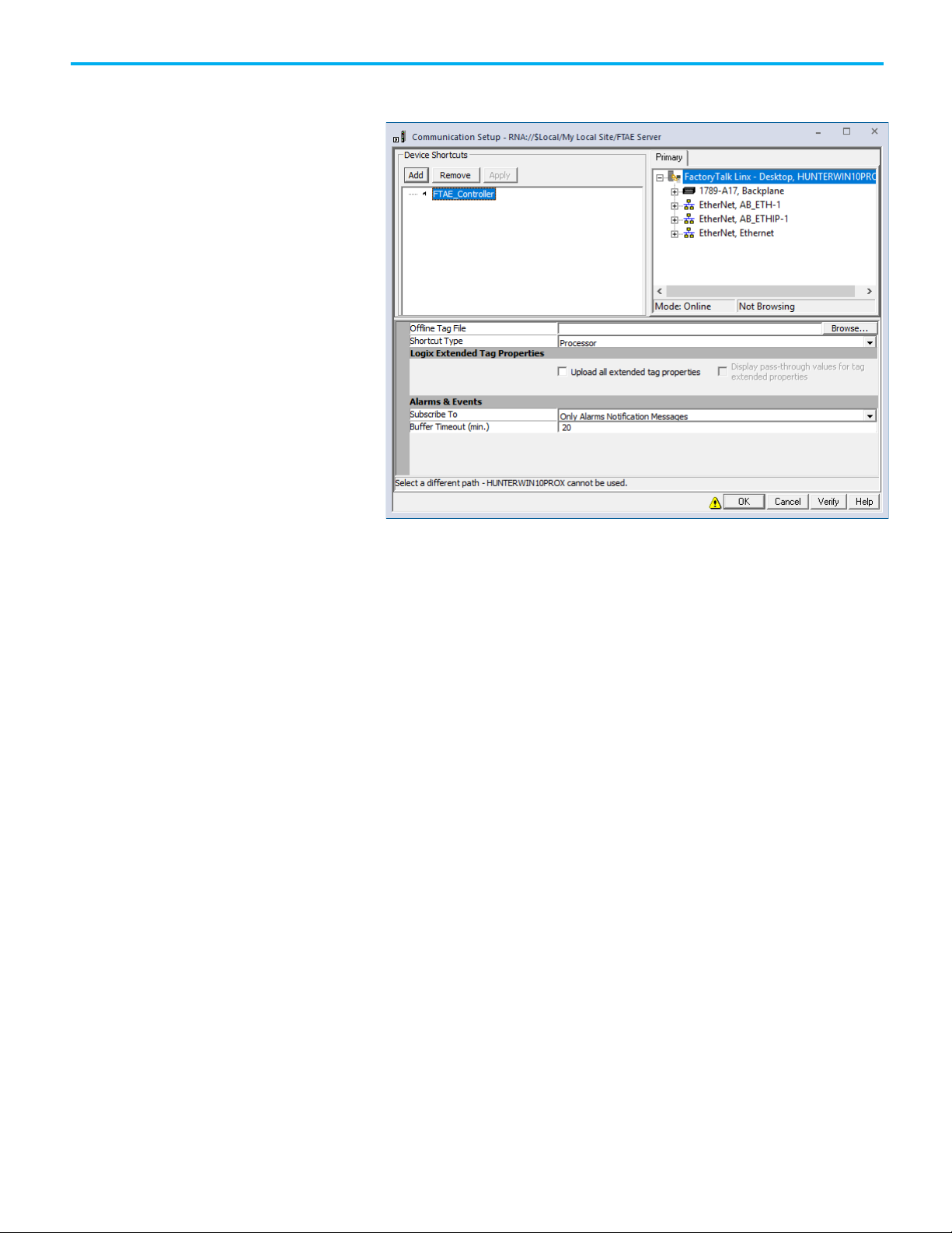
Chapter 7 Add a tag-based alarm server for Logix 5000, PLC-5, SLC 500, or third-party controllers
Add a Tag Alarm and Event
2. In the Communication Setup dialog box, click the Add button and
en type a name for the new shortcut. We use FTAE_Controller.
th
Server
ome options in this dialog box might be different if you are using
S
PLC-5 or SLC 500 controllers.
The warning icon beside the OK button indicates that changing values
in this dialog box at runtime can cause unexpected results. For details,
click Help.
3. On the Primary tab, expand the list of networks and devices until the
controller is visible, and then click the controller. To set the path to the
primary controller, click the Apply button.
4. To save the shortcut configuration and close the Communication
Setup dialog box, click OK.
To create a server and define alarm conditions that monitor tags for PLC-5,
SLC 500 controllers, or Logix 5000 controllers, complete the following steps.
These instructions apply to FactoryTalk View Studio. For help with
FactoryTalk Administration Console, click Start > All Programs > Rockwell
Software > FactoryTalk Tools > FactoryTalk Help.
Add a Tag Alarm and Event Server
1. In the Explorer window, right-click the application. Point to Add New
Server, and then click Tag Alarm and Event Server.
2. In the Tag Alarm and Event Server Properties dialog box, click the
General tab.
Rockwell Automation Publication FTAE-RM001M-EN-E - March 2021
55
Page 56

Chapter 7 Add a tag-based alarm server for Logix 5000, PLC-5, SLC 500, or third-party controllers
Define alarm conditions
3. Type a name for the server, and then click OK. In this example, we use
agAE.
T
4. On the Priorities and History tab, clear the Enable history check box.
The Priorities and History tab is used to configure alarm and even
logging. Set up historical alarm and event logging on page 101
describes how to set up alarm logging for a Tag Alarm and Event
S
erver.
5. To create the Tag Alarm and Event Server and close the dialog box,
click OK.
After creating a Tag Alarm and Event Server, define the conditions that will
trigger alarms at runtime.
This example shows how to create a digital alarm in a Tag Alarm and Event
Server.
1. In the Explorer window, expand the TagAE server, and then double-
click Alarm and Event Setup.
2. In the Alarm and Event Setup dialog box, click the New button on
the toolbar, and then click Digital.
t
56
3. In
the Digital Alarm Properties dialog box, type a name for the alarm.
In this example we use Valve1FTO
Rockwell Automation Publication FTAE-RM001M-EN-E - March 2021
.
Page 57

Chapter 7 Add a tag-based alarm server for Logix 5000, PLC-5, SLC 500, or third-party controllers
Next steps
4. To select an Input Tag for the alarm, click the Browse button (...), and
then expand the folder tree until you can select the online tag you plan
to monitor.
5. S
elect the tag you plan to monitor and then click OK. In this exampl
e used Valve1FTO_alm.
w
6. In the Digital Alarm Properties dialog box, type a message. In this
example, in the Message field we type The valve failed to open.
You can also embed variables within the message. For details, click
Help on any tab in the Alarm Setup dialog box.
7. To close the Digital Alarm Properties dialog box, click OK.
8. To save the alarm and start monitoring for the alarm condition, click
Save.
e
Do the following:
1. Define additional alarms and (optionally) define alarm groups.
2. After you define alarms and groups, you can add FactoryTalk Alarms
and Events objects to graphic displays. See Set up graphic displays
page 59.
3. If your FactoryTalk network station application or network distributed
plication plan calls for data redundancy, you will want to configure
ap
your tag-based alarm server and tag data servers for redundancy. We
recommend completing this step after the FactoryTalk application is
fully configured and all HMI features have been tested using nonredundant servers. Adding data and alarm server redundancy does no
a
ffect the configuration of the graphic displays in the HMI application.
Rockwell Automation Publication FTAE-RM001M-EN-E - March 2021
on
t
57
Page 58

Chapter 7 Add a tag-based alarm server for Logix 5000, PLC-5, SLC 500, or third-party controllers
IMPORTANT
See Configure redundancy for alarms and events on page 119 for more
information.
FactoryTalk Alarms and Events redundancy and data server redundancy are only
supported in network station applications and network distributed applications.
58
Rockwell Automation Publication FTAE-RM001M-EN-E - March 2021
Page 59

Chapter 8
Before you begin
What you need
Follow these steps
Set up graphic displays
Create graphic displays in FactoryTalk View Studio. These are containers for
objects, such as the FactoryTalk Alarm and Event Summary object. Add
FactoryTalk Alarms and Events objects to graphic displays so that an operator
can monitor and interact with device-based, tag-based alarms, and diagnostic
events at runtime.
Other graphic objects (for example, objects representing equipment) can be
animated (for example, to change color) using FactoryTalk View Site Edition
expression functions that monitor the state of alarms. See
animation to indicate alarm state changes on page 74. Also see FactoryTalk
View Site Edition Help.
This section describes how to create graphic displays, and then create and
configure the FactoryTalk Alarms and Events graphic objects and macros that
determine how the graphic displays open in the FactoryTalk View Site Edition
Client. This section is one example of how you might create your graphic
displays.
Use color
• Define the alarms you plan to use, as described in
alarms in Logix 5000 controllers on page 29.
• Add the required device server, as described in Add a device server for
Logix 5000, PLC-5, or SLC 500 controllers on page 39 or Add a tagbased alarm server for Logix 5000, PLC-5, SLC 500, or third-party
controllers on page 51.
• FactoryTalk Linx software
• FactoryTalk View Studio software
Follow these steps to set up graphic displays:
• Add a device server or add a tag-based alarm server
• Run FactoryTalk View Studio and open an application
• Create a graphic display
• Add an Alarm and Event Summary object
• Configure the object's properties
• Create a graphic display
• Add an Alarm and Event Banner object
• Configure the object's properties
• Create a startup macro
• Create a graphic display
• Add an Automatic Diagnostic Event Summary object
• Configure the object's properties
Define device-based
Rockwell Automation Publication FTAE-RM001M-EN-E - March 2021
59
Page 60

Chapter 8 Set up graphic displays
Create a graphic display
• Animate a display with expressions
• Monitor and interact with alarms during runtime
• Set up historical alarm and event logging
Create a graphic display to host FactoryTalk Alarms and Events objects, such
as the Alarm and Event Summary.
Step 1. Open an existing application in FactoryTalk View Studio
1. To run FactoryTalk View Studio, click Start > All Programs > Rockwell
Software > FactoryTalk View > FactoryTalk View Studio.
2. In the Application Type Selection window, select View Site Edition
(Local Station) and then click Continue.
3. In the New/Open Site Edition (Local Station) Application dialog box
cl
ick the Existing tab, and select the application you created in
device server for Logix 5000, PLC-5, or SLC 500 controllers on page 39
(we used My Local Site).
Add a
,
60
Rockwell Automation Publication FTAE-RM001M-EN-E - March 2021
Page 61

Tip: You cannot use the Alarm and Event Summary to enable or turn alarm suppression off. To enable or
To silence an alarm, use the Alarm and Event Banner.
Create an Alarm and Event
Chapter 8 Set up graphic displays
Step 2. Create a graphic display to host FactoryTalk Alarms and
Events objects
1. In the Explorer window, expand the Graphics folder, right-click
Displays, and then click New.
A blank display appears in the workspace. Next, add Factory Talk
Alarm and Event objects to the graphic display.
Use the Alarm and Event Summary object to view and interact with a
Summary
summary of all the current alarms and events in an application. You can
acknowledge, suppress, disable, shelve, or unshelve alarms.
turn alarm suppression off, use the Alarm Status Explorer. See Monitor alarms and events on page 87.
You can use FactoryTalk Security to control which users can acknowledge,
enable, disable, reset, suppress, shelve, or unshelve alarms at runtime in an
application (or in an area). To do this, right-click the application (or area) and
then click Security. For details, see the FactoryTalk Security System Configuration
Guide.
Rockwell Automation Publication FTAE-RM001M-EN-E - March 2021
61
Page 62

Chapter 8 Set up graphic displays
Step 1. Add an Alarm Summary to a graphic display
1. On the Objects menu, point to Alarm and Event, click Summary (or in
the toolbox, select Alarm and Event Summary), and then place th
rsor approximately where the object is to be on the display.
cu
2. Hold the left mouse button down and drag it to create a rectangle the
size that the Alarm and Event Summary object should be.
3. When the object is the desired size, release the left mouse button. Th
larm and Event Summary object is drawn on the display.
A
e
e
Step 2. Change the settings of the Alarm and Event Summary display
1. On the menu bar, click Edit > Display Settings.
62
Rockwell Automation Publication FTAE-RM001M-EN-E - March 2021
Page 63

Chapter 8 Set up graphic displays
Tip: In any application, do not include more than two graphic displays that have Cache After
processor cycles.
Displaying and Always Updating set because these options can consume large numbers of
2. In the Display Settings dialog box, on the Properties tab, make the
fo
llowing changes and then click OK.
• Under Cache After Displaying, click Yes and then select the Always
Updating check box.
When you set Cache After Displaying to Yes, the display stays in
memory cache when you close it. This shortens the time required to
open the graphic display the next time.
When you select the Always Updating check box, the displa
c
ontinues to be updated with changes in alarm states when it is
y
cached. This shortens the time necessary to update the Alarm and
Event Summary with current alarms when you open it again.
If Cache After Displaying is set to No, and the Always Updating
check box is cleared, every time you close the graphic display, all
alarms are removed from the Alarm and Event Summary. When you
re-open the graphic display, the Alarm and Event Summary is blank
nd then begins to receive the most recent alarms when they occur.
a
,
• Clear the Title Bar check box.
• Select the Size to Main Window at Runtime check box.
• Select the Allow Display to be Resized check box.
• Under When Resized, select the Scale check box is if it is not already
selected.
Step 3. Save the display
1. On the File menu, click Save.
2. In the Save dialog box, type a name for the new display and then click
OK.
We use Alarm and Event Summary in this example.
3. Close the graphic object.
Rockwell Automation Publication FTAE-RM001M-EN-E - March 2021
63
Page 64
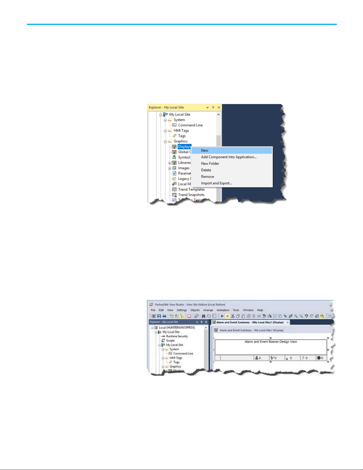
Chapter 8 Set up graphic displays
Create an Alarm and Event
Banner display
This section describes how to add an Alarm and Event Banner object to a
graphic display, and then create a startup macro that docks the Banner to the
bottom of the FactoryTalk View Site Edition Client window.
Step 1. Create a new graphic display
1. In the Explorer window, expand the Graphics folder.
2. Right-click Displays, and then click New.
Step 2. Add an Alarm and Event Banner object to the display
1. On the Objects menu, point to Alarm and Event, click Banner (or, in
the toolbox, select Alarm and Event Banner), and then place the
cursor approximately where the object is to be on the display.
2. Hold the left mouse button down and drag it to create a rectangle the
size that the Alarm and Event Banner should be.
3. When the object the desired size, release the left mouse button. The
Alarm and Event Banner object is drawn on the display.
64
Rockwell Automation Publication FTAE-RM001M-EN-E - March 2021
Page 65

Chapter 8 Set up graphic displays
4. Resize the graphic display so that the Banner fills the graphic display
(do not leave white space). Do so because the Banner displays no more
than five alarms at a time.
Step 3. Configure the properties of the Alarm and Event Banner
1. To open the Alarm and Event Banner Properties dialog box, double-
click the Alarm and Event Banner object. For details about all of the
properties in the dialog box, click Help.
2. On the General tab, click the Browse button (...) under Alarm and
Event Summary command.
This opens the Command Wizard where you will create a command to
start the Alarm and Event Summary graphic display from the Alarm
and Event Banner.
Rockwell Automation Publication FTAE-RM001M-EN-E - March 2021
65
Page 66
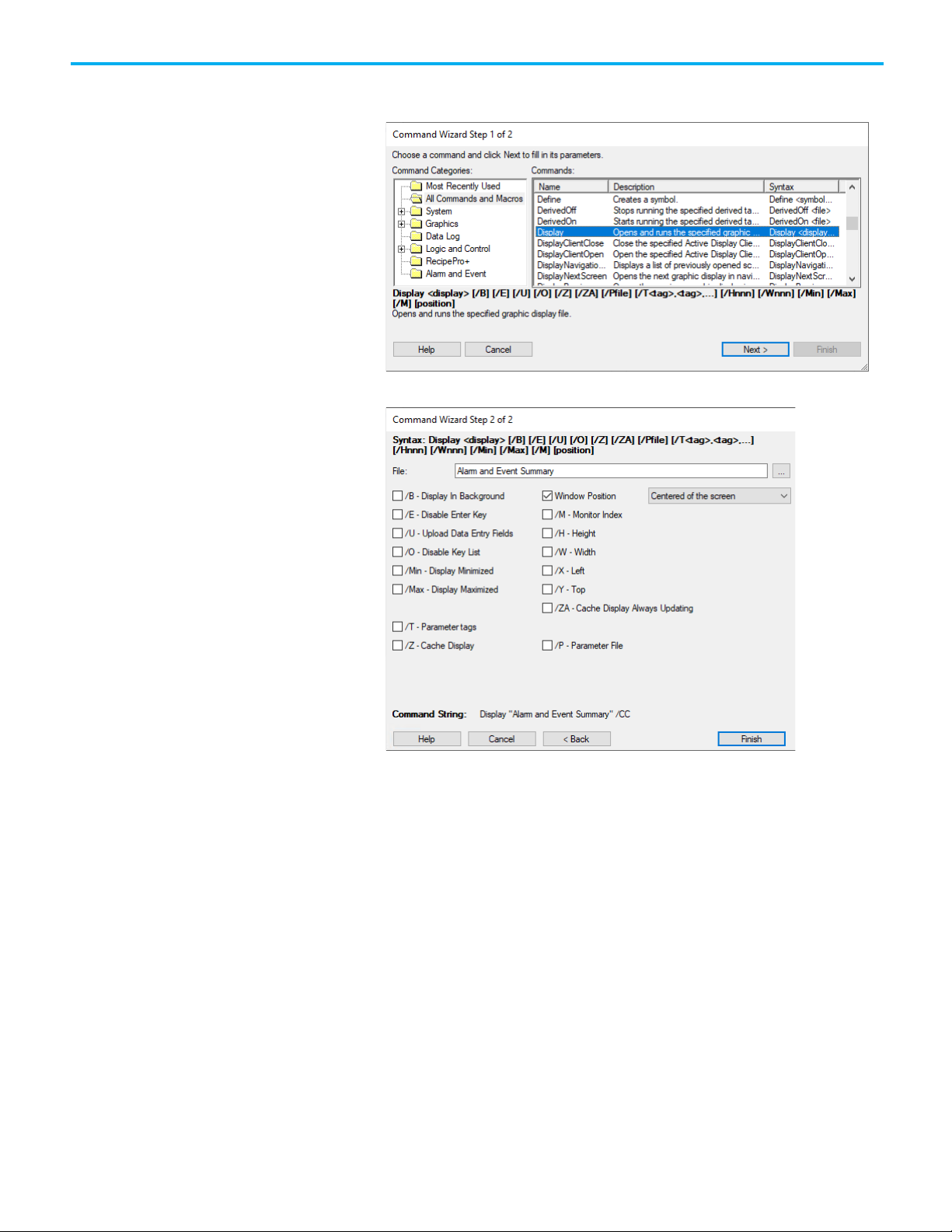
Chapter 8 Set up graphic displays
3. Scroll down the list of commands on the right side of the wizard, select
isplay, and then click Next.
D
4. In
the File list, click Alarm and Event Summary.
66
elect the Window Position check box. Scroll down the list on the righ
5. S
and then click Centered of the screen.
Rockwell Automation Publication FTAE-RM001M-EN-E - March 2021
t
Page 67
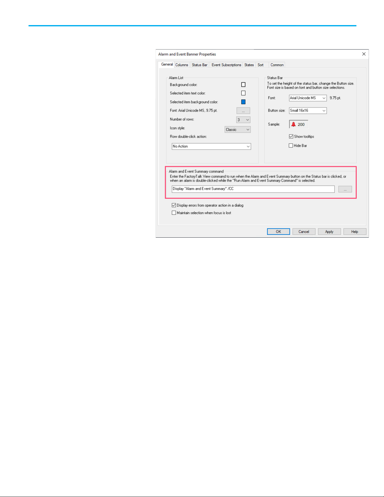
Chapter 8 Set up graphic displays
6. Click Finish to save the Display command and add it to the Alarm and
Event Banner Properties dialog box.
ick OK to close the dialog box.
7. Cl
Step 4. Change the display settings for the Alarm and Event Banner
display
1. On the Edit menu, click Display Settings.
Rockwell Automation Publication FTAE-RM001M-EN-E - March 2021
67
Page 68

Chapter 8 Set up graphic displays
2. In the Display Settings dialog box, on the Properties tab, make the
llowing changes, and then click OK:
fo
lear the Title Bar check box.
• C
• Select Size to Main Window at Runtime.
• Select Allow Display to be Resized.
• Under When Resized, select Scale if it is not already selected.
3. The Alarm and Event Banner graphic display is always visible because
it is docked. You do not need to turn on Cache After Displaying, as you
did for the Alarm and Event Summary object. See step 2: "Change the
settings of the Alarm and Event Summary display" in
Create an Alarm
and Event Summary on page 61.
Step 5. Save the graphic display
1. On the File menu, click Save.
2. In the Save dialog box, type a name for the graphic display and then
click OK.
In this example, we use Alarm and Event Banner.
68
lose the graphic display.
3. C
Rockwell Automation Publication FTAE-RM001M-EN-E - March 2021
Page 69
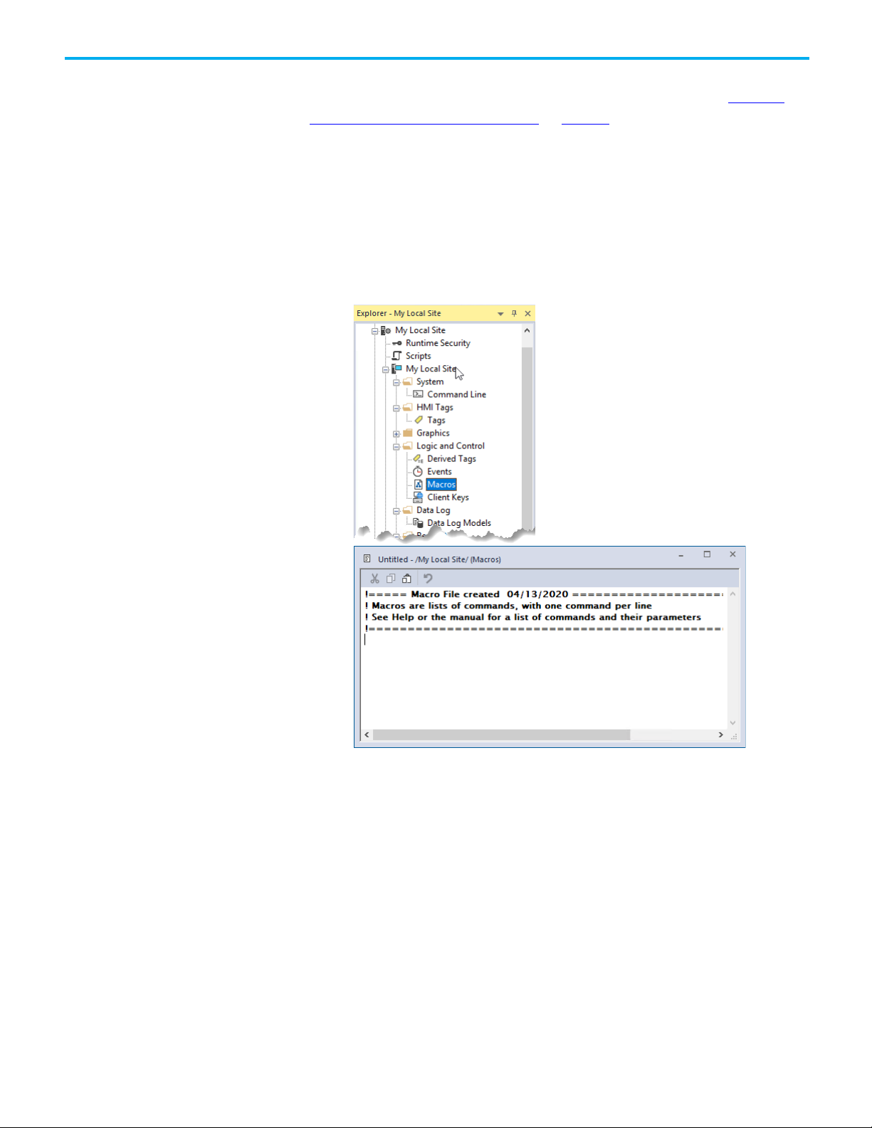
Create a startup macro for
the Banner display
Chapter 8 Set up graphic displays
This section describes how to create a startup macro. You will use the macro
when you configure the FactoryTalk View Site Edition Client. See
and interact with alarms at runtime on page 83.
Monitor
Step 1. Configure a startup macro
This startup macro docks the Banner display to the bottom of the FactoryTalk
View SE Client window.
1. In FactoryTalk View Studio, in the Explorer window, right-click
Macros and then click New to open the editor.
2. To open the Command Wizard, double-click anywhere in the body of
th
e macro editor.
Rockwell Automation Publication FTAE-RM001M-EN-E - March 2021
69
Page 70

Chapter 8 Set up graphic displays
Create an Automatic
3. In the Command Wizard, scroll down the list of commands on the
right side of the wizard, click Display, and then click Next.
4. In
the File list, click Alarm and Event Banner.
Diagnostic Event Summary
70
elect the Window Position check box. Scroll down the list on the righ
5. S
and then select Docked to the bottom.
6. To save the Display command and add it to the macro, click OK.
Step 2. Save the macro
1. On the File menu, click Save.
2. In the Save dialog box, type a name for the new macro and then click
OK. In this example, we use Start Alarm and Event Banner.
se the Automatic Diagnostic Event Summary object to subscribe to and
U
show diagnostic events collected by Rockwell Automation controllers via
Rockwell Automation Publication FTAE-RM001M-EN-E - March 2021
t
Page 71

Chapter 8 Set up graphic displays
Ethernet. It is enabled by the Automatic Diagnostics feature. Automatic
Diagnostics is supported only on Compact GuardLogix 5380, CompactLogix
5380, CompactLogix 5480, ControlLogix 5580, and GuardLogix 5580
controllers, and the firmware revision must be 33 or later. With the Automatic
Diagnostic Event Summary, you can suppress, unsuppress, filter, and sort
diagnostic events at runtime.
You can use FactoryTalk Security to control which users can suppress or
unsuppress events at runtime in an application (or in an area). To do this,
right-click the application (or area) and then click Security. For details, see the
FactoryTalk Security System Configuration Guide.
Step 1. Create a new graphic display
1. In the Explorer window, expand the Graphics folder.
2. Right-click Displays, and then click New.
Step 2. Add an Automatic Diagnostic Event Summary object to the
display
1. On the Objects menu, point to Alarm and Event, click Automatic
Diagnostic Event Summary (or, in the toolbox, select Automatic
Diagnostic Event Summary), and then place the cursor approximately
where the object is to be on the display.
2. Hold the left mouse button down and drag it to create a rectangle the
size that the Automatic Diagnostic Event Summary should be.
Rockwell Automation Publication FTAE-RM001M-EN-E - March 2021
71
Page 72

Chapter 8 Set up graphic displays
3. When the object the desired size, release the left mouse button. The
Automatic Diagnostic Event Summary object is drawn on the display.
Step 3. Configure the properties of the Automatic Diagnostic Event
Summary
• To open the Automatic Diagnostic Event Summary Properties dialog
x, right-click the Automatic Diagnostic Event Summary object. For
bo
details about all of the properties in the dialog box, click Help.
Step 4. Change the display settings for the Automatic Diagnostic Event
Summary display
1. On the Edit menu, click Display Settings.
72
Rockwell Automation Publication FTAE-RM001M-EN-E - March 2021
Page 73
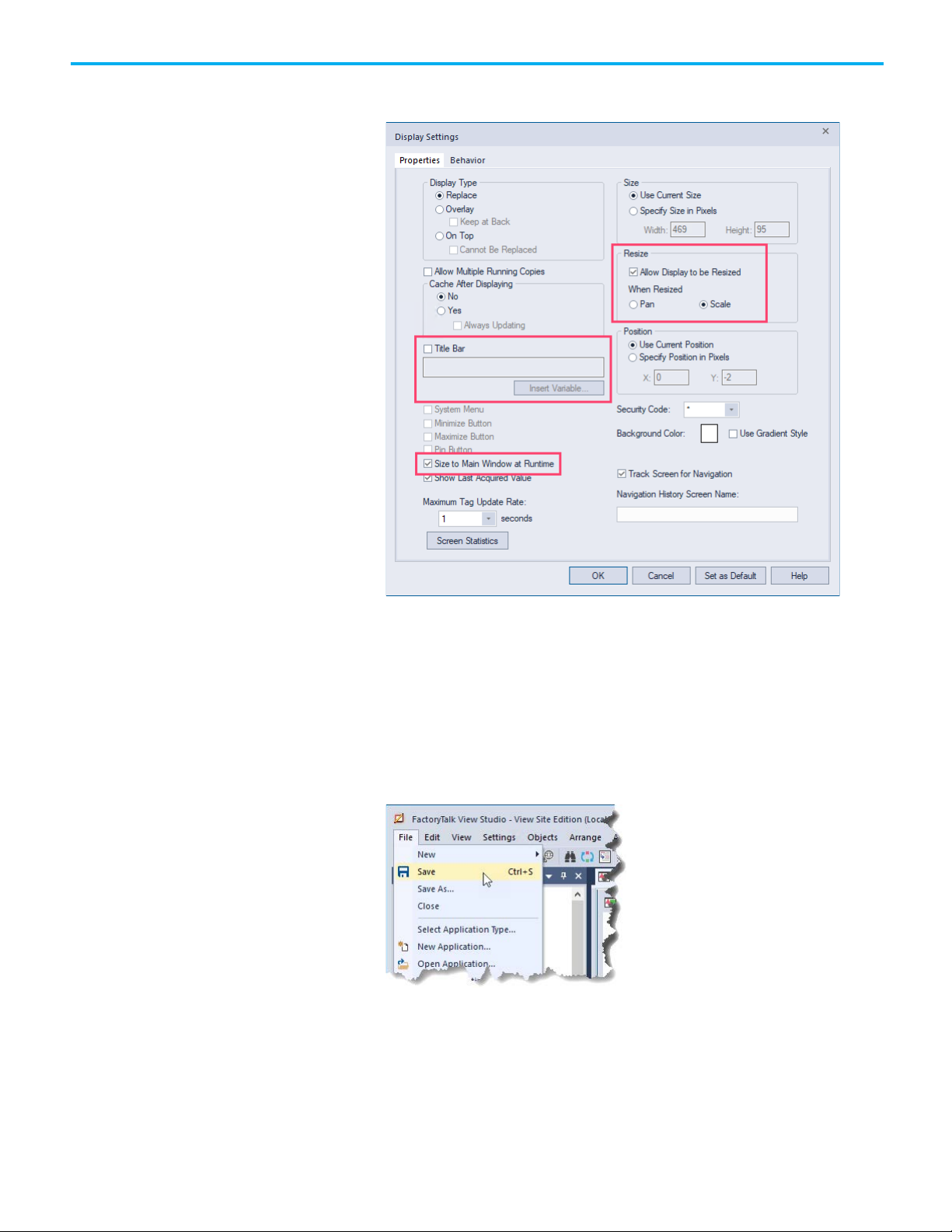
Chapter 8 Set up graphic displays
2. In the Display Settings dialog box, on the Properties tab, make the
llowing changes, and then click OK:
fo
lear the Title Bar check box.
• C
• Select Size to Main Window at Runtime.
• Select Allow Display to be Resized.
• Under When Resized, select Scale if it is not already selected.
Step 5. Save the graphic display
1. On the File menu, click Save.
2. In the Save dialog box, type a name for the graphic display and then
click OK.
Rockwell Automation Publication FTAE-RM001M-EN-E - March 2021
73
Page 74

Chapter 8 Set up graphic displays
Use color animation to
indicate alarm state
changes
In this example, we use Automatic Diagnostic Event Summary.
3. Close the graphic display.
In this section, you use alarm expressions in FactoryTalk View to animate a
rectangle on a graphic display so that it changes color when the alarm state
changes at runtime:
• If there are active unacknowledged alarms, the rectangle flashes red.
• If all active alarms have been acknowledged, the rectangle is a steady
red.
• If there are no active alarms but there are normal unacknowledged
alarms, the rectangle is yellow.
• If there are no active or unacknowledged alarms, the rectangle is
green.
Step 1. Create a new graphic display
1. In the Explorer window, expand the Graphics folder.
2. Right-click Displays, and then click New.
Step 2. Add an Alarm and Event Summary to the graphic display
1. On the Objects menu, point to Alarm and Event, and then click
Summary (or in the toolbox, click Alarm and Event Summary).
2. Hold the left mouse button down and drag it to create a rectangle the
size that the Alarm and Event Summary object should be.
3. When the object is the desired size, release the left mouse button. Th
A
larm and Event Summary object is drawn on the display.
e
74
necessary, resize either the Alarm and Event Summary object or th
4. If
graphic display to expose enough white space at the top, bottom, or on
Rockwell Automation Publication FTAE-RM001M-EN-E - March 2021
e
Page 75

Chapter 8 Set up graphic displays
Tip: In the preceding expression, "*" means include all alarms that are in the same location
("/AreaName::*").
one side to add a rectangle object that will be the alarm status
indicator.
n the Objects menu, point to Drawing and then click Rectangle.
5. O
6. In the graphic display, hold down the left mouse button and then drag
e mouse to draw a box for the alarm status indicator.
th
Step 3. Add an expression to animate the rectangle
1. Right-click the rectangle, point to Animation and then click Color.
To create an expression for the color animation, you can compose the
expression step by step, as explained in the following steps, or you can
type the following expression in the Expression box:
If AE_InAlmUnackedCount( "*" ) > 0 Then 0 Else
If AE_InAlmAckedCount( "*" ) > 0 Then 1 Else
If AE_NormalUnackedCount( "*" ) > 0 Then 2 Else 3
Rockwell Automation Publication FTAE-RM001M-EN-E - March 2021
(area) as the HMI server. If the preceding expression is used in a network station application
or network distributed application with areas, the expression would include all alarms from
the alarm servers that are located in the same area as the HMI server.
If you want to include alarms from other areas, use the absolute path syntax. For example,
75
Page 76
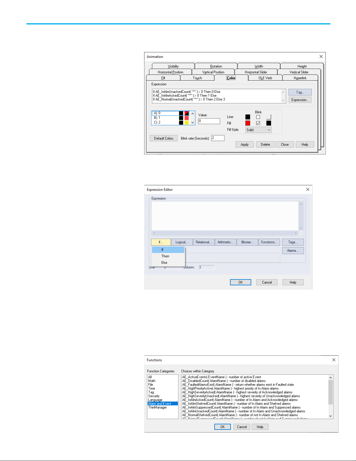
Chapter 8 Set up graphic displays
If you type the expression instead of composing it, skip to the next
major step "Step 4. Set up colors for the alarm states" to apply colors to
each state.
the Animation dialog box, click Expression.
2. In
3. In the Expression Editor, click the If button and then click If to add
the IF condition.
76
4. In the Expression Editor, click Functions.
5. In the Functions dialog box, in the list of Function Categories, click
Alarm and Event.
The HMI Tag Alarming category contains functions that apply only to
HMI tags located in an HMI server. Because our alarm data is coming
from a controller or a FactoryTalk Tag Alarm and Event Server, we use
the Alarm and Event expressions.
Rockwell Automation Publication FTAE-RM001M-EN-E - March 2021
Page 77

Chapter 8 Set up graphic displays
6. In the list of functions on the right, click
AE_InAlmUnackedCount(AlarmName), and then click OK.
7. In the Expression Editor, the AE_InAlmUnackedCount( ) functio
a
ppears in the Expression box, with the cursor between the
parentheses. Next, type "*" to return a count of all alarms that are in
the same location (area) as the HMI server and are in the In Alarm and
Unacknowledged state. Next, move the cursor to the right of the
closing parenthesis.
n
To count the number of instances of a specific alarm, you can type
g name instead of the asterisk.
ta
To include alarms from other areas, use the absolute path syntax. For
example,
("/AreaName::*").
8. Click Relational and then click > GT for greater than.
. In the Expression box, type 0, click If and then click Then to add a
9
THEN condition.
a
This completes the IF condition: "If the number of In Alarm,
Unacknowledged alarms is greater than 0 . . ."
0. In the Expression box, type 0, click If and then click Else to add an
1
ELSE condition.
Rockwell Automation Publication FTAE-RM001M-EN-E - March 2021
77
Page 78

Chapter 8 Set up graphic displays
This completes the THEN condition: "If the number of In Alarm,
Unacknowledged alarms is greater than 0, then animate the rectangle
to show the colors for state 0."
11. Follow the same process, substituting the necessary selections to add
the remaining two expressions, and then click OK.
If AE_InAlmAckedCount( "*" ) > 0 Then 1 Else (animates the
rectangle to show the colors for state 1)
If AE_NormalUnackedCount( "*" ) > 0 Then 2 Else 3 (animates the
rectangle to show the colors for state 2. If none of the conditions are
true, the expression animates the rectangle to show the colors for
state 3.)
Step 4. Set up colors for the alarm states
This step describes how to set up colors for the rectangle for each solution to
the expression.
1. In the Animation dialog box, under Expression, click state A.
n the Value box, type 0.
2. I
3. Beside Fill, select the Blink check box. A colored box is displayed so
that you can specify an alternative color.
78
Rockwell Automation Publication FTAE-RM001M-EN-E - March 2021
Page 79

Chapter 8 Set up graphic displays
4. Beside Fill, make sure the colored boxes are set to red (for the fill color)
and black (for the blinkalternative color).
5. Set up the colors for the remaining states:
• State B: Value = 1, Line = Black, Fill = Red
• State C: Value = 2, Line = Black, Fill = Yellow
• State D: Value = 3, Line = Black, Fill = Green
6. When you are finished setting up the colors, click Apply and then click
C
lose.
Step 5. Save the graphic display
1. On the File menu, click Save.
2. In the Save dialog box, type a name for the graphic display and then
click OK.
In this example, we use Alarm Status Indicator.
Step 6: Test run the display
1. On the View menu, click Test Display, or click the Test Display button
(
shown at left) on the toolbar.
If there are unacknowledged alarms whose alarm condition is In
Alarm, the rectangle flashes red.
Rockwell Automation Publication FTAE-RM001M-EN-E - March 2021
79
Page 80

Chapter 8 Set up graphic displays
2. Right-click one of the alarms, and then click Ack All. Because all active
alarms have been acknowledged, the rectangle changes to a steady red.
ontinue experimenting to observe the effects of acknowledgin
3. C
arms:
al
g
• If there are no active alarms, but there are normal unacknowledged
alarms, the rectangle is yellow.
• If there are no active or unacknowledged alarms, the rectangle is
green.
80
4. W
hen you are finished, on the View menu, click Edit Display, or click
the Edit Display button on the toolbar.
Rockwell Automation Publication FTAE-RM001M-EN-E - March 2021
Page 81

Chapter 8 Set up graphic displays
Next steps
Do one of the following:
• Use the graphic displays you just created to monitor and interact with
alarms and events. See Monitor and interact with alarms at runtime
page 83.
• Set up historical alarm and event logging. See Set up historical alarm
and event logging on page 101.
on
Rockwell Automation Publication FTAE-RM001M-EN-E - March 2021
81
Page 82

Page 83

Chapter 9
IMPORTANT
For this example, be sure that the controller is running the West_Plant_Controller program
contact and then click Toggle Bit).
Before you begin
What you need
Follow these steps
Create and then run a
Monitor and interact with alarms at runtime
To interact with alarms and events at runtime, set up a FactoryTalk View Site
Edition Client and configure one or more graphic displays that host Alarm
and Event objects. Next, run the client and then monitor the alarms and
events that are shown.
• Be sure you have defined alarms as described in
alarms in Logix 5000 controllers on page 29.
• Add the appropriate device server as described in Add a device server
for Logix 5000, PLC-5, or SLC 500 controllers on page 39 or Add a tagbased alarm server for Logix 5000, PLC-5, SLC 500, or third-party
controllers on page 51.
• Set up and configure any graphic display objects as described in Set up
graphic displays on page 59.
• FactoryTalk Linx software
• FactoryTalk View SE software
• FactoryTalk View SE Client software
Follow these steps to monitor and interact with alarms during runtime:
• Set up graphic displays
• Run FactoryTalk View SE Client wizard and create a configuration file
• Run the FactoryTalk View SE Client
• Monitor graphic displays with Alarm and Event objects
• Acknowledge an alarm
• Disable and enable an alarm
• Suppress and unsuppress an alarm
• Set up historical alarm and event logging
Define device-based
To run an application and monitor graphic displays for alarm messages, start
FactoryTalk View Client
the FactoryTalk View Site Edition Client.
configuration
Rockwell Automation Publication FTAE-RM001M-EN-E - March 2021
that we created in Chapter 3, and that you have tripped the alarm (right-click the rung
83
Page 84

Chapter 9 Monitor and interact with alarms at runtime
Step 1. Create a FactoryTalk View Site Edition Client configuration file
1. To open the FactoryTalk View SE Client Wizard, in Windows, click
Start > All Programs > Rockwell Software > FactoryTalk View
Fa
>
ctoryTalk View Site Edition Client.
the FactoryTalk View SE Client Wizard, click Create a FactoryTalk
2. In
View SE Client configuration file.
3. On the File name and location page, in Client file name, type a name
for the configuration file. In this example, we used Alarms and Events
Demo. Select a path for the configuration file and click Continue.
84
Rockwell Automation Publication FTAE-RM001M-EN-E - March 2021
Page 85

Chapter 9 Monitor and interact with alarms at runtime
4. On the Startup components page, select Local Station.
In
the Connect to the application list, select the name of the
application you plan to connect to. In this example, use the My Local
Site application created in Set up graphic displays on page 59
In the Startup macro list, select Start Alarm and Event Banner, and
then click Advanced.
.
5. On the Client window properties page, configure how the FactoryTalk
View SE Client window will look at runtime. In this example, we
entered Show Me Alarms in the Title bar text box. At runtime, this tex
displayed at the top of the Client window. Click Security and
is
debugging.
t
Rockwell Automation Publication FTAE-RM001M-EN-E - March 2021
85
Page 86
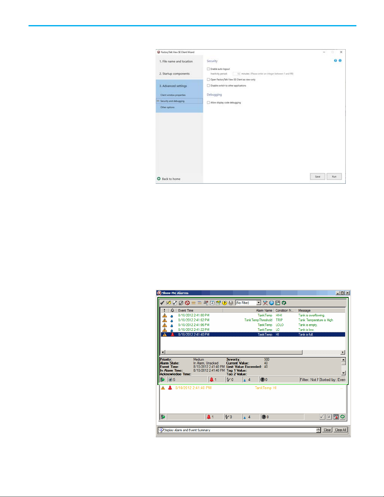
Chapter 9 Monitor and interact with alarms at runtime
6. On Security and debugging page, you can configure the Client to log
ut automatically after a period of inactivity.
o
7. Cl
ick Save, and then Run.
The Client window opens with the Alarm and Event Banner docked a
e bottom.
th
Step 2. Open the Alarm and Event Summary from the Alarm and Event
Banner
In the Alarm and Event Banner, click the Alarm and Event Summary
button (shown at left). The Alarm and Event Summary opens, and is
similar to the following graphic display.
t
86
Rockwell Automation Publication FTAE-RM001M-EN-E - March 2021
Page 87
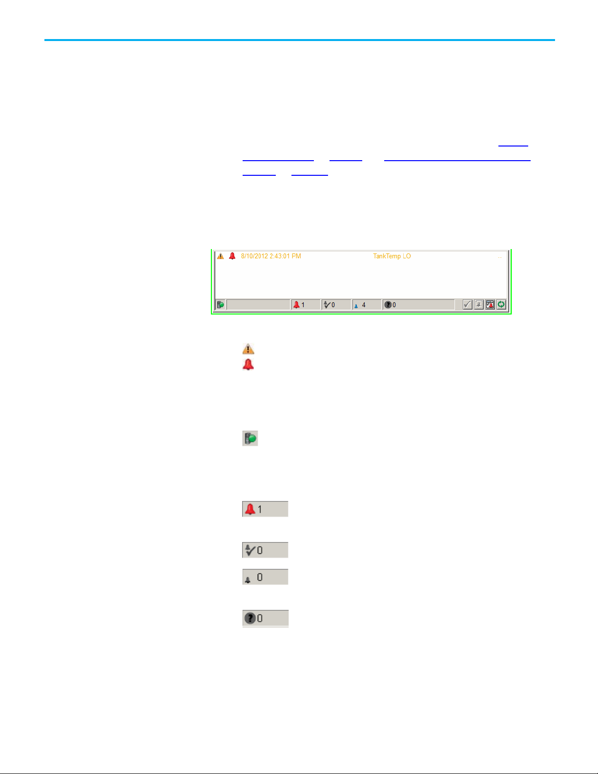
Monitor alarms and events
Chapter 9 Monitor and interact with alarms at runtime
Step 3. Next steps
Do either of the following:
• Monitor and interact with alarms and events as shown in the next
section.
• Set up historical logging for alarms and events using the graphic
displays and startup macros created in this chapter and in
graphic displays on page 59. See Set up historical alarm and event
logging on page 101.
The data fields in the Alarm and Event Banner window are organized in
columns, and represent various alarm and event data. At runtime, only the
columns that were configured at design time to be visible are displayed in the
Alarm and Event Banner.
Set up
n this example, the alarm list shows these columns:
I
• Priority - Medium
• Alarm State - In Alarm and Unacknowledged
• Event time and date stamp
• Message
The status bar shows (from left to right):
The connection status of the Tag Alarm and Event Server -whether connected or disconnected from the Alarm and Event Banner.
The green icon shows that the Tag Alarm and Event Server is
connected. When disconnected, the icon flashes red.
The number of alarms that are In Alarm and
Unacknowledged
The number of alarms that are In Alarm and Acknowledged
The number of alarms that are Normal and
Unacknowledged
The number of alarm faults
For all of the possible priorities and alarms states that can be shown in the
Alarm and Event objects, see FactoryTalk Alarms and Events Help:
1. In Windows, click Start > All Programs > Rockwell Software >
FactoryTalk Alarms and Events > User Documentation > FactoryTalk
Alarms and Events Help
Rockwell Automation Publication FTAE-RM001M-EN-E - March 2021
.
87
Page 88

Chapter 9 Monitor and interact with alarms at runtime
Tip: The Digital Alarm Properties, Level Alarm Properties, and Deviation Alarm Properties dialog
See FactoryTalk Alarms and Events Help for more information on using the Control Tags tab.
Security for alarms and
Acknowledge an alarm
Acknowledge the selected
2. In the section "Monitor alarms during runtime," see these topics:
a. Alarm and Event Summary > About the columns in the Alarm and
b. Alarm Status Explorer > About the columns in the Alarm Status
c. Alarm and Event Log Viewer > About the columns in the Alarm and
You can use FactoryTalk Security to control which users can acknowledge,
events
enable, disable, reset, suppress, or shelve alarms at runtime in an application
(or in an area).
To do this, in FactoryTalk View Studio or FactoryTalk Administration Console,
right-click the application (or area) where the alarms are located and then
click Security. For details, see the FactoryTalk Security System Configuration
Guide. In Windows, click Start > Rockwell Software > FactoryTalk Tools >
FactoryTalk Security System Configuration Guide.
When you acknowledge an alarm it does not correct the condition causing the
alarm, but it indicates that an operator is aware of the alarm.
Event Summary
Explorer
Event Log Viewer
alarm
boxes each contain a Control Tags tab that allows you to acknowledge alarms by using tags in the
controller (remote acknowledgment).
• At runtime, the alarm state in graphic objects changes to Acknowledged when the remote
acknowledge tag value is changed to positive.
• The alarm import and export functions support remote acknowledgment.
A single tag might have several alarm conditions In Alarm. Each alarm
condition must be acknowledged separately. For example, a tag that monitors
a temperature might trigger HI and HIHI alarm conditions by the time it is
acknowledged. The alarm could also go In Alarm and Out of Alarm several
times before it is acknowledged.
Previous occurrences of an alarm that have gone Out of Alarm and then back
In Alarm cannot be acknowledged. These older occurrences are referred to as
out of scope and are displayed in the alarm list with a different icon. When the
most recent occurrence of an alarm is acknowledged, previous occurrences
are removed from the alarm list.
In the Alarm and Event Summary event list, do one of the following:
• Select the alarms you want to acknowledge, and then click the
Acknowledge selected alarm button .
88
Rockwell Automation Publication FTAE-RM001M-EN-E - March 2021
Page 89
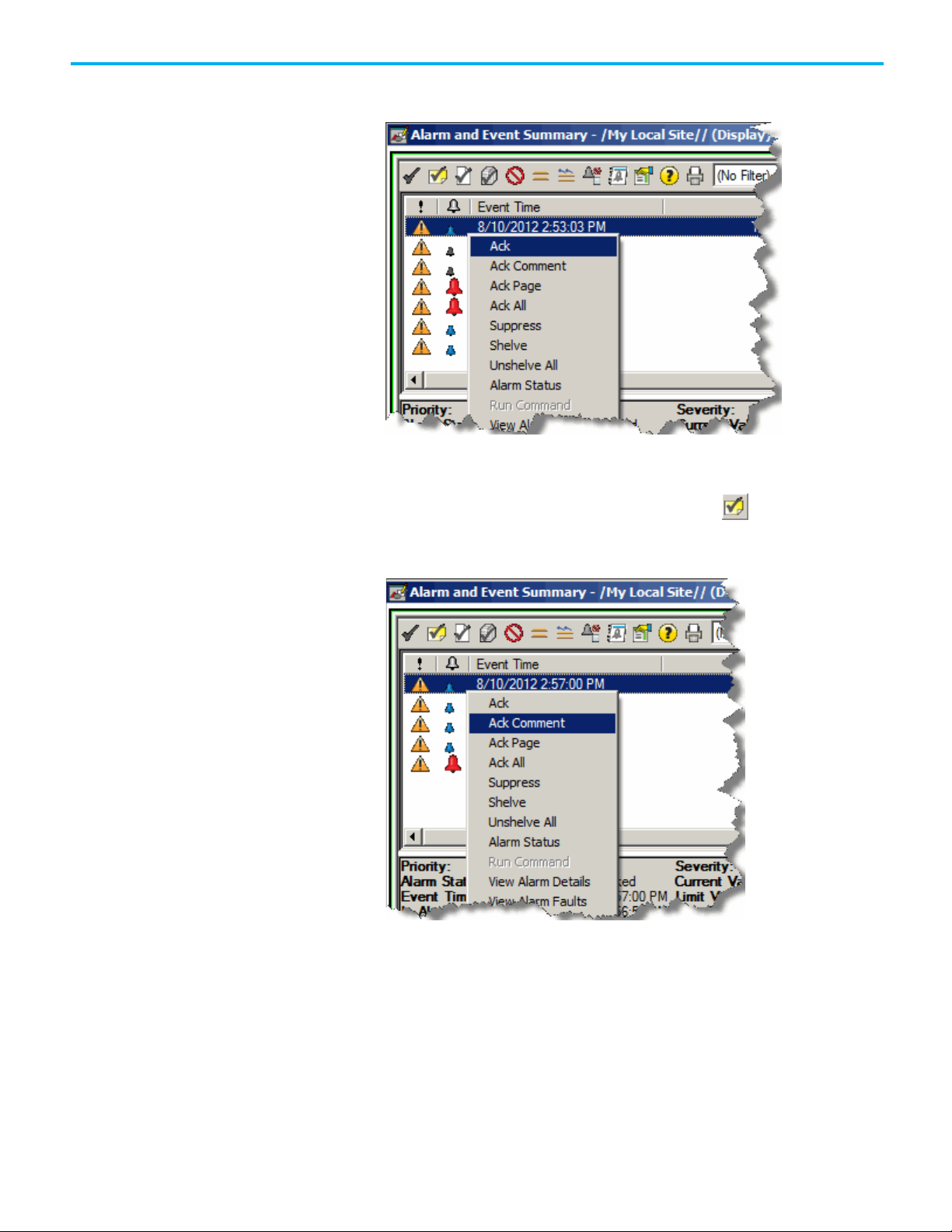
Chapter 9 Monitor and interact with alarms at runtime
Acknowledge the selected
• Select the alarms you want to acknowledge, right-click the selected
alarms, and then click Ack.
the Alarm and Event Summary event list, do one of the following:
1. In
alarm and enter a comment
• Select the alarms you want to acknowledge, and then click
Acknowledge selected alarm with comment .
• Select the alarms you want to acknowledge, right-click the selected
alarms, and then click Ack Comment.
the Acknowledge Alarm with Comment dialog box, type a
2. In
comment, and then click Acknowledge. If historical logging is set up,
Rockwell Automation Publication FTAE-RM001M-EN-E - March 2021
89
Page 90

Chapter 9 Monitor and interact with alarms at runtime
Acknowledged, and so on) to view the comment associated with that state.
Acknowledge all of the
Acknowledge all of the
the comment is displayed in the Alarm and Event Log as part of the
Tracking event that is generated from the Acknowledge command.
the Alarm and Event Summary toolbar, do one of the following:
In
Tip: You can view the last comment that was entered for an operation (for example, ack,
disable, suppress) in the Alarm Details dialog box. To view a comment associated with an
alarm state, select an alarm and then click the Show details for the selected alarm button on
the toolbar. In the Alarm Details dialog box, expand an alarm state (Disabled, Suppressed,
alarms displayed on the
page
• Click Ack page of alarms . All alarms currently visible in the event
list are acknowledged.
• Right-click one of the alarms and then click Ack Page.
In
the Alarm and Event Summary toolbar, do one of the following:
alarms in the event list
90
Rockwell Automation Publication FTAE-RM001M-EN-E - March 2021
• Click Acknowledge all alarms contained in list . All alarms in the
event list are acknowledged, even if they are not all visible. However, if
the list is filtered, alarms that are filtered out are not acknowledged.
Page 91

Chapter 9 Monitor and interact with alarms at runtime
Tip: Disable alarms that are related to equipment that is being shut down or serviced.
IMPORTANT
You can use FactoryTalk Security to control who can disable or suppress alarms. If a user
those operations on the context (shortcut) menu.
Disable or enable an alarm
Disable selected alarms
• Right-click one of the alarms, and then click Ack All.
hen an alarm is disabled the operator is not notified when the alarm
W
condition occurs and the alarm is removed from the Alarm and Event Banner.
• An alarm that is disabled is effectively turned off in the controller.
• The alarm condition is no longer monitored and notifications are not
generated by the controller.
• Disabled alarms do not sound the alarm bell in the Alarm and Even
ner
Ban
.
t
• Unacknowledged disabled alarms are displayed in the Alarm and Event
Summary
U
nlike a silenced alarm, a disabled alarm does not trigger the alarm bell in the
.
Alarm and Event Banner if the alarm condition occurs again after the alarm
was disabled.
To enable alarms, use the Alarm Status Explorer. See Enable selected alarms
on page 92.
When an alarm is enabled, the operator is notified when the alarm condition
occurs. Enabled alarms sound the alarm bell, and continue appearing as new
events in the Alarm and Event Summary, unless they are suppressed.
1. I
n the Alarm and Event Summary event list, do one of the following:
Rockwell Automation Publication FTAE-RM001M-EN-E - March 2021
attempts to perform an operation for which they do not have the required security rights,
the operation will fail and a message will be displayed stating that the user has
insufficient rights to perform the operation. To add another level of security, the Alarm
and Event Summary can be configured not to show the toolbar buttons, which also hides
91
Page 92

Chapter 9 Monitor and interact with alarms at runtime
Alarm Status Explorer to enable alarms.
Enable selected alarms
• Select the alarms you want to disable, and then on the toolbar, click
• Select the alarms you want to disable, right-click the selected
the Disable selected alarm button.
alarms, and then click Disable.
the Disable Alarm dialog box, type a comment (for example, to
2. In
explain why the alarm is disabled) and then click Disable.
This comment is stored with the alarm and is logged to the Comment
field in the Alarm and Event Log, which you can view using the Alarm
and Event Log Viewer.
Tip: Any alarms you disable stay in that state until you enable them again. You must use the
1. I
n the Alarm and Event Summary window, do one of the following:
• If it is visible on the toolbar, click the Display the Alarm Status
92
Explorer button .
Rockwell Automation Publication FTAE-RM001M-EN-E - March 2021
Page 93

Chapter 9 Monitor and interact with alarms at runtime
Suppress or unsuppress an
• If the toolbar button is not visible, right-click an alarm in the Alarm
and Event Summary event list, and then click Alarm Status.
n the Alarm Status Explorer window, select the alarms you want to
2. I
enable and then click the Enable selected alarm button .
alarm
Any alarms you enable stay in that state until you disable them again.
For details about the other features of the Alarm Status Explorer, click
Help in the dialog box.
You can suppress an alarm that is not needed temporarily, for example,
suppress an alarm that is caused by another alarm that you are already
addressing. You can suppress or unsuppress up to 2000 alarms at one time.
• A suppressed alarm is not displayed in the Alarm and Event Banner.
If an alarm is displayed in the Alarm and Event Banner and then
suppressed, it is removed from the alarm list.
• An unacknowledged suppressed alarm is displayed in the Alarm an
Ev
ent Summary.
If an alarm is displayed in the Alarm and Event Summary and then
suppressed, it is only removed from the alarm list when it is
acknowledged.
Rockwell Automation Publication FTAE-RM001M-EN-E - March 2021
d
93
Page 94

Chapter 9 Monitor and interact with alarms at runtime
Suppress an alarm
Unsuppress an alarm
• A suppressed alarm continues to be logged in the alarm history log,
which you can view using the Alarm and Event Log Viewer. See
historical alarm and event logging on page 101 for more information.
• A suppressed alarm also continues to set the appropriate InAlarm
parameters of an alarm instruction in the controller.
Disable an alarm instead of suppressing it if you want to completely turn off
the alarm detection logic for the alarm source and prevent the alarm from
being detected. See Disable selected alarms on page 91
1. In the Alarm and Event Summary event list, do one of the following:
• Select the alarms you want to suppress and then click the Suppress
• Select the alarms you want to suppress, right-click the selected
Set up
.
selected alarm button .
alarms, and then click Suppress.
94
the Suppress Alarm window, optionally type a comment, and then
2. In
click Suppress.
comment is stored with the alarm and is logged to the Comment
A
field in the Alarm and Event Log, which you can view using the Alarm
and Event Log Viewer.
Rockwell Automation Publication FTAE-RM001M-EN-E - March 2021
Page 95

Chapter 9 Monitor and interact with alarms at runtime
FactoryTalk Help.
Unsuppress an alarm that was previously suppressed if it now needs to be
monitored again. For example, an operator might have suppressed an alarm
because the alarm was caused by another alarm that an operator was already
attending to.
An unacknowledged suppressed alarm is displayed in the Alarm and Event
Summary.
To unsuppress an alarm, follow these steps:
1. In the Alarm and Event Summary, right-click an alarm and then click
Alarm Status.
the Alarm Status Explorer window, select the alarm or alarms you
2. In
want to unsuppress, and then on the toolbar click the Unsuppress
selected alarm button.
Tip: You can filter alarm sources to make it easier to find the alarm you want. In the Name box,
type all or part of an alarm name, or select an alarm status from the list. You can use the * and
? wildcard characters in the filter. For details about filtering alarm sources, see FactoryTalk
Help. In Windows, click Start > All Programs > Rockwell Software > FactoryTalk Tools >
Rockwell Automation Publication FTAE-RM001M-EN-E - March 2021
95
Page 96
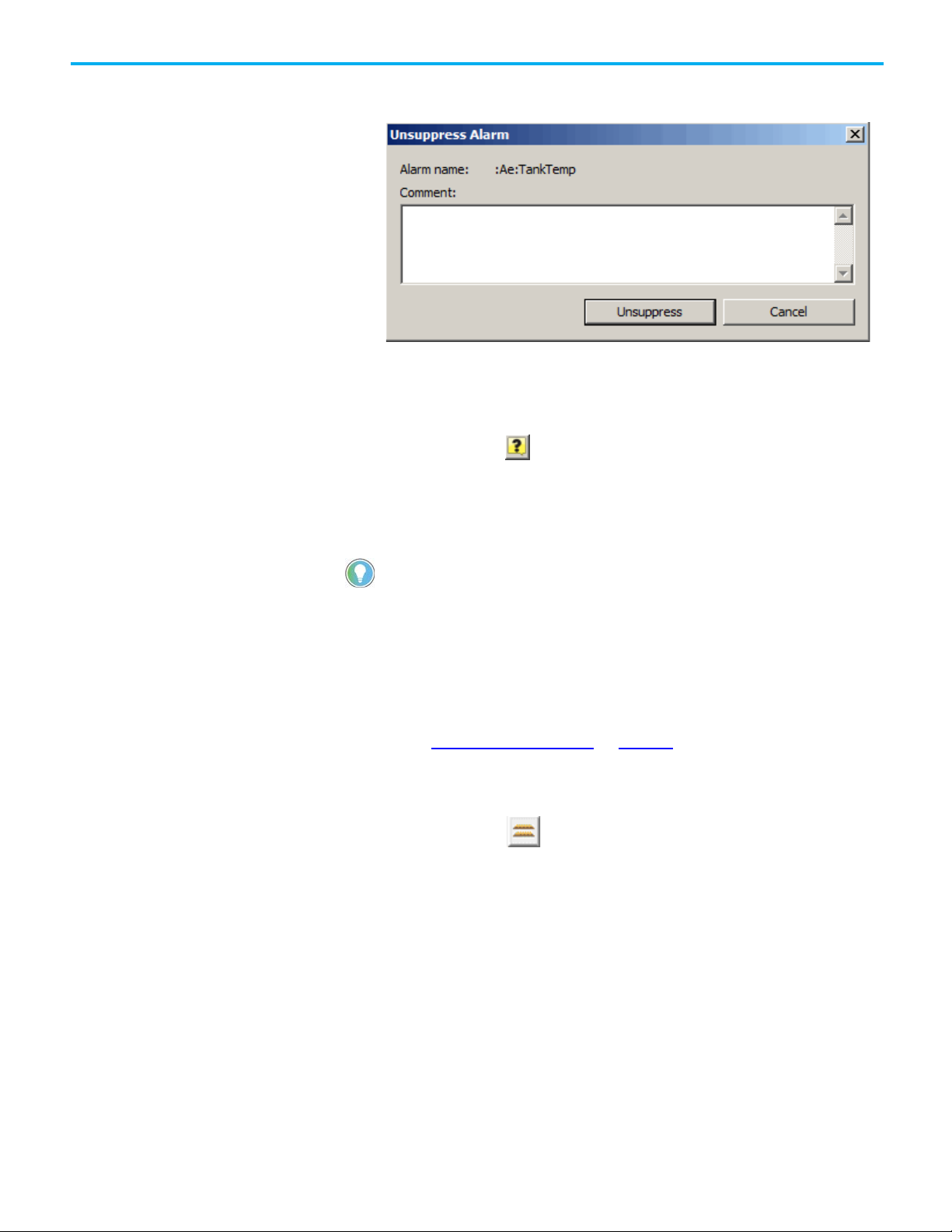
Chapter 9 Monitor and interact with alarms at runtime
Shelve or unshelve an alarm
Shelve an alarm
3. In the Unsuppress Alarm dialog box, optionally type a comment on
why the alarm is unsuppressed, and then click Unsuppress.
T
his comment is stored with the alarm and is logged to the Comment
field in the Alarm and Event Log, which you can view using the Alarm
and Event Log Viewer if historical logging has been configured.
For details about the other features of the Alarm Status Explorer, click
the Help button .
Shelving an alarm temporarily suppresses it. When shelving, the operator
specifies a duration for the alarm to remain shelved. The alarm is
automatically unshelved when the duration runs out.
Tip: Shelving is supported in the Logix Designer application version 21 or later.
A shelved alarm is displayed in the Alarm and Event Summary or Alarm
Status Explorer. However, a shelved alarm is not displayed in the Alarm and
Event Banner.
Disable an alarm, instead of shelving it, if you want to completely turn off the
alarm detection logic for the alarm source, and prevent the alarm from being
detected. See Disable selected alarms on page 91
1. In the Alarm and Event Summary event list, do one of the following:
• Select the alarm you want to shelve and click the Shelve selected
alarm button on the toolbar.
for more information.
96
Rockwell Automation Publication FTAE-RM001M-EN-E - March 2021
Page 97

Chapter 9 Monitor and interact with alarms at runtime
Field
Description
Alarm name
Shows the name of the selected alarm.
Comment
(
optional
) Specifies the reason for shelving the alarm.
• Right-click the alarm you want to shelve and select Shelve.
2. T
he Shelve Alarm dialog box appears.
n the dialog box, enter the following information if desired:
I
If multiple alarms are selected, this shows as
where x is the total count of selected alarms.
Shelve duration Specifies the period of time the alarm should be shelved. Once the shelve
duration expires, the alarm is unshelved. The value must be a whole number.
• Default: 1
• Minimum: 1
• Maximum: 2147483647
The default value is empty. The maximum length is 512 characters.
This comment is stored with the alarm and is logged to the UserComment
field in the alarm database, which you can view using the Alarm and Event
Log Viewer.
Multiple (x alarms selected)
3. When complete, click Shelve.
When you reshelve alarms, the conditions vary depending on the type of
alarms:
Rockwell Automation Publication FTAE-RM001M-EN-E - March 2021
97
Page 98
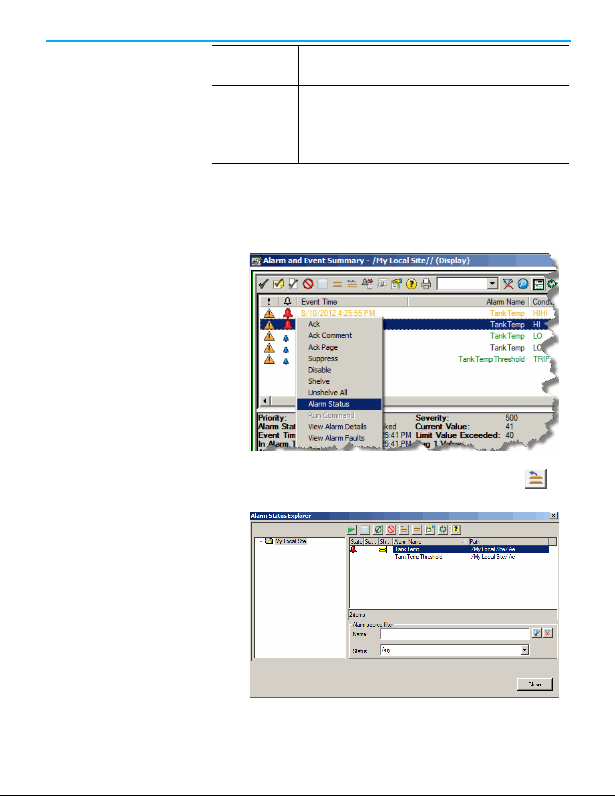
Chapter 9 Monitor and interact with alarms at runtime
Alarm type
Alarm condition
A digital alarm
The alarm is shelved with the new specified duration. The alarm unshelve time is also
updated accordingly.
An analog alarm
If one or more of the alarm conditions you reshelve were previously shelved, the alarm
Unshelve an alarm
If alarms that were previously shelved need to be monitored again, you can
unshelve the specified alarms in the Alarm Status Explorer.
1. In the Alarm and Event Summary window, right-click an alarm and
then click Alarm Status.
condition is shelved with the new specified duration and the alarm unshelve time is also
updated accordingly.
If none of the alarm conditions you reshelve were previously shelved, the alarm condition
is shelved targeting to the old unshelve time.
2. In
unshelve, and then click the Unshelve selected alarm button on
the toolbar.
the Alarm Status Explorer, select the alarm or alarms you want to
98
Rockwell Automation Publication FTAE-RM001M-EN-E - March 2021
Page 99

Chapter 9 Monitor and interact with alarms at runtime
3. In the Unshelve Alarm dialog box, optionally enter a comment about
y the alarm is unshelved, and then click Unshelve.
wh
T
he comment is stored with the alarm and is logged to the Comment
field in the Alarm and Event Log, which you can view using the Alarm
and Event Log Viewer if historical logging has been configured.
You can also unshelve all shelved alarms in the Alarm and Event Summary:
1. In the Alarm and Event Summary event list, do one of the following:
2. On the toolbar, click the Unshelve all alarms button .
• Right-click an alarm in the list, and then click Unshelve All.
Rockwell Automation Publication FTAE-RM001M-EN-E - March 2021
99
Page 100
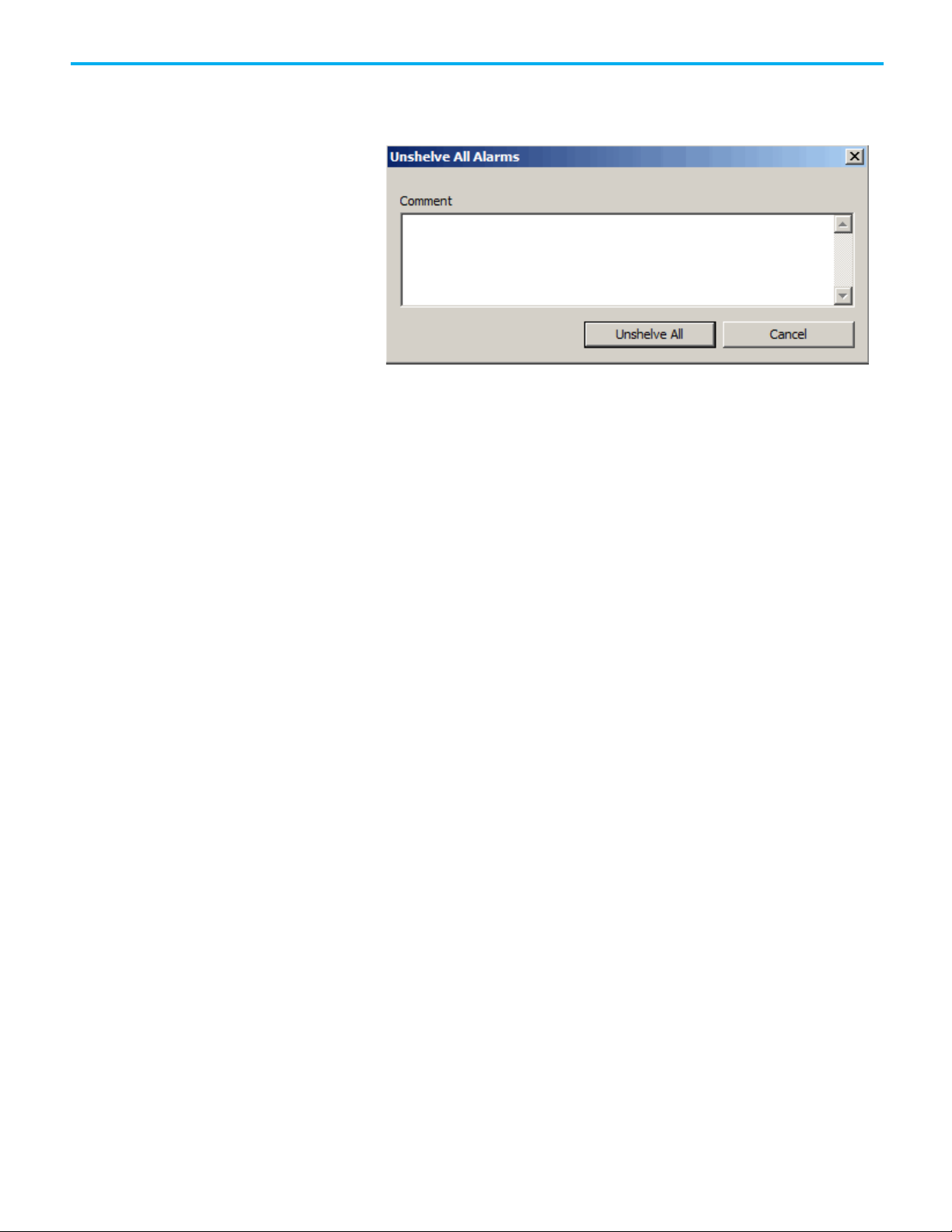
Chapter 9 Monitor and interact with alarms at runtime
3. The Unshelve All Alarms dialog box appears. Optionally enter a
comment on why the alarms are unshelved and then click Unshelve
All.
100
Rockwell Automation Publication FTAE-RM001M-EN-E - March 2021
 Loading...