

Page 1
Installation Instructions
F la sh Fir m ware Kit
Catalog Number F1770-KFC(D)15
What’s in These Installation Instructions?
These installation instructions describe how to upgrade the
1770-KFC and 1770-KFCD ControlNetTM RS-232 Interfa ce M odule
firmware from ControlNet phase 1.25 to phase 1.5.
Importa nt: A qualified service tech nician must perform the firmware
upgrade procedure.
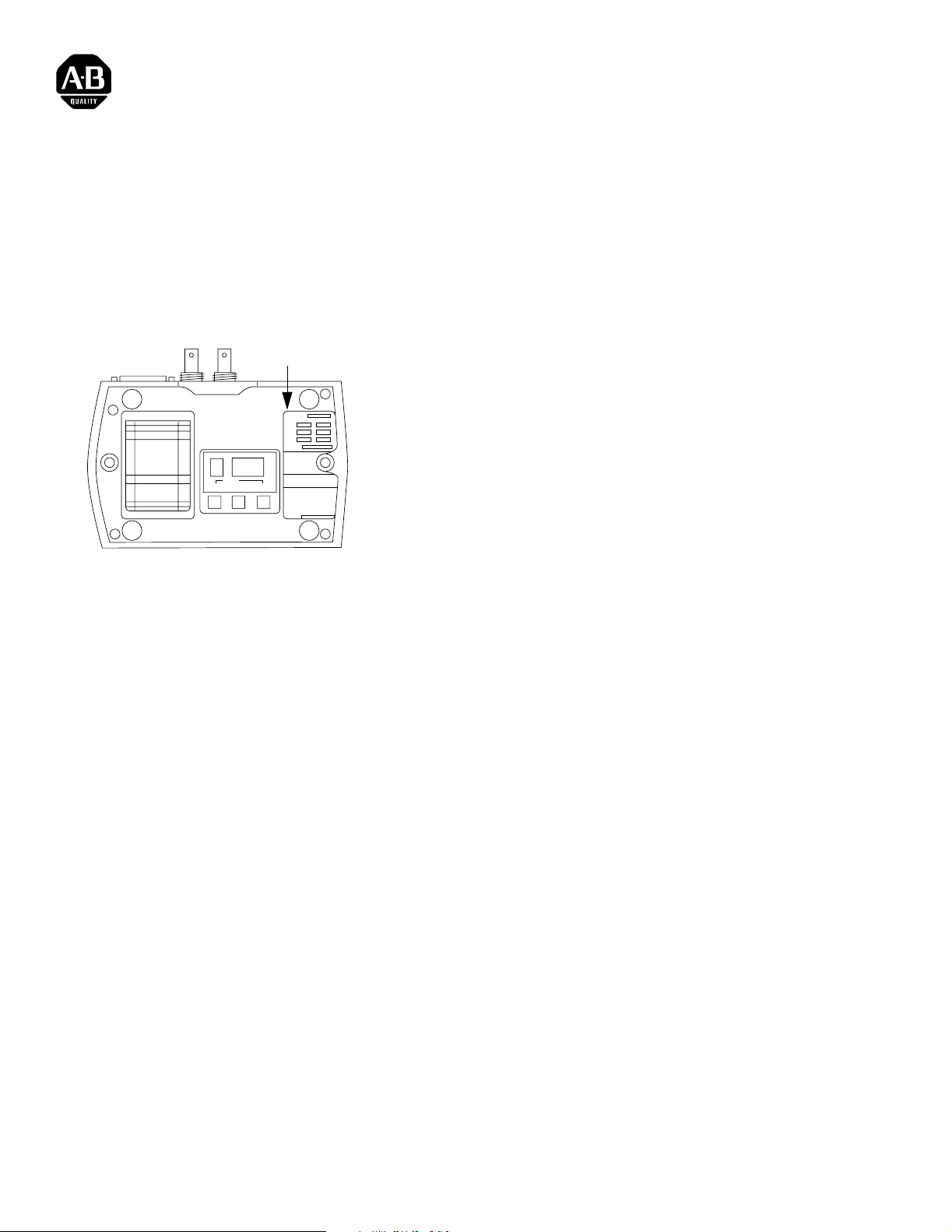
Label
The upgrade procedures appl y to the 1770-KFC and 1770-KF CD
modules listed below. You can find the series and revision on the
product ID label on the bottom of the module as shown in the figure
to the left.
SAVE
VIEW DATA EXIT
• 1770-KFC, series A, revision A (non-CE module)
• 1770-KFC, series B, revision A (CE module)
Bottom of Module
30580-M
• 1770-KFCD, series A, revision A (CE module)
Before You Begin Importa nt: The 1770-KFC series A requires a factory ha rdware
modification before it can be upgra ded. If it has been
modified, you will see “1770-KFCD Phase 1.5” on the
label. If you have a series A module that needs to be
modified, exchange it through the Allen-Bradley parts
hub through your local sales office.
What the Kit Contains The 1770-KFC and 1770-KFCD firmware upgrade kit includes:
• one jumper
• one disk with flash utilitie s and binary files
• one patch label
• these Flash Firmware Kit Installation Instructions
Publication 1770-5.9 - May 1998
Page 2
2 Flash Firmware Kit
What You Must Provide You must provide the following two pieces of hardware for this
upgrade:
• A 386 (or better) IBM-comp atible PC booted in DOS 6.22 or later .
ATTENTION: Do not run this utility from
Microsoft® Windows 95® or Windows NT™ in the
!
You can run the flash upgrade tool from the disk or from your
PC’s hard drive.
• A serial cable to connect your comput er’s COM port to the module,
such as:
•1784-CP10 (9 pin to 25 pin)
•1784-CP11 (25 pin to 25 pin)
DOS window while operati ng Windows 95 or Windows
NT .
Both cables require a female-to-female gender changer.
Prepare the Module The 1770-KFC and the 1770-KFCD firmware are comprised of a
boot section and an executive (main code) section. You must first
upgrade the executive section and then the boot section.
Install the Jumper
ATTENTION: Disconnect power be fore openin g the
module. A qualified service techni cian must perform
!
!
the upgrade procedure.
ATTENTION: Circuit boards are highly sensitive to
electrostatic discharge (ESD). Ha ndling a circui t board
without ESD protection ca n cause ser ious dam age that
might not be apparent during ins tallation or initial use.
T o guard against ESD damage, before handling the
module, put on a grounding wrist-strap and touch a
grounding object to d ischarge any built- up static charge.
Publication 1770-5.9 - May 1998
Page 3
Flash Firmware Kit 3
1. Carefully remove the cover by removing the four screws on the
bottom of the module.
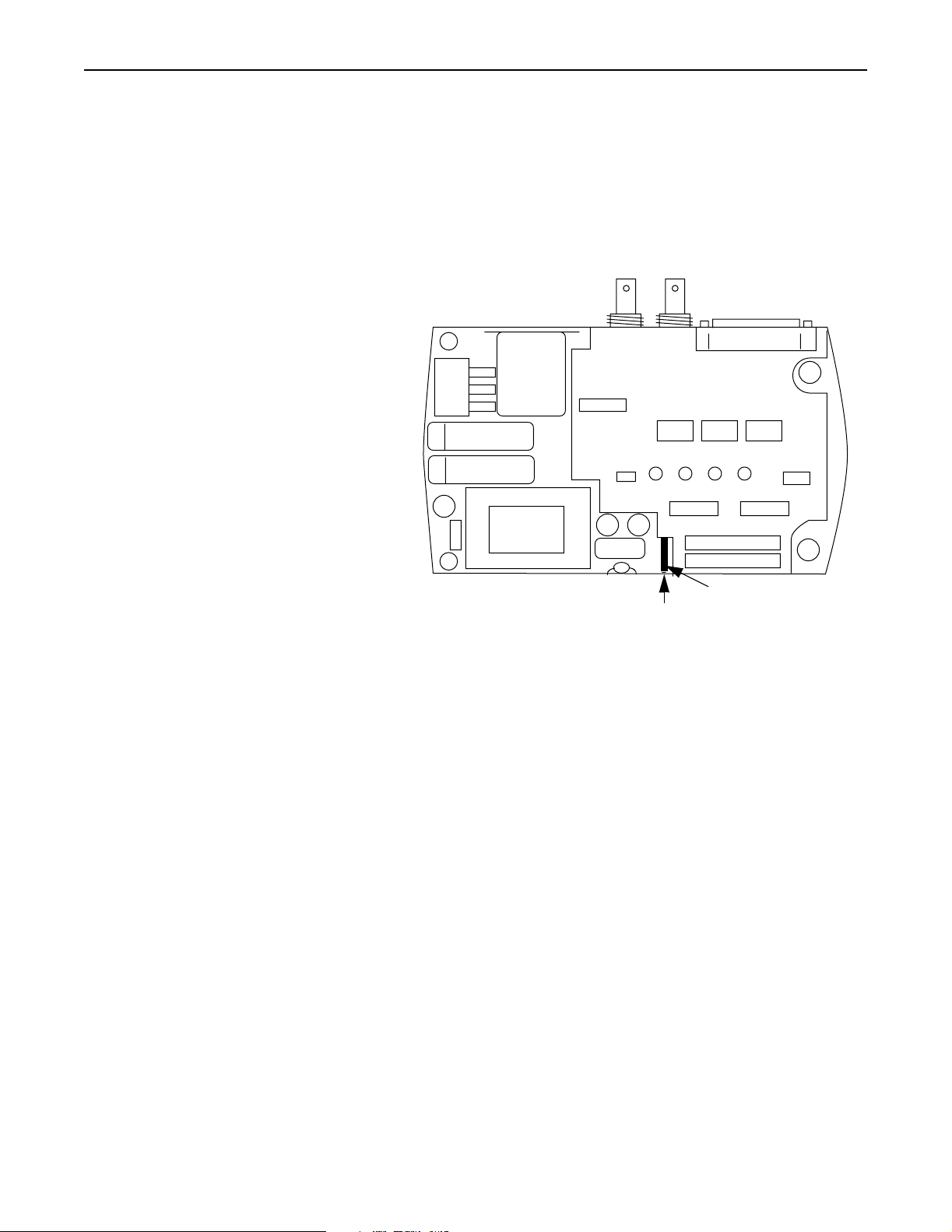
2. Enable the boot section by insta lling the jumper onto the Boot
Block Enable header. The Boot Block Enable he ader i s l ocated on
the main printed circuit board inside the module as shown below.
Inside of Module
Jumper
Boot Block Enable header
Now that the jumper is installed, you will not need to remove it
during the life of the module.
3. Replace the cover and four screws.
4. Connect the module to either available COM port of your
computer.
Importa nt: Do not connect the module to the ControlNet
network. (Do not make connec tions t o BNC or NAP
ports).
5. Connect the AC or DC power cord and apply power.
Next you will reset the module parameters.
30582-M
Publication 1770-5.9 - May 1998
Page 4

4 Flash Firmware Kit
ControlNet Communication Interface
HOST
AB
STATUS
30579-M
Front of Module
Reset Module Parameters
Importa nt: Before you reset the parameters, make sure you record
any configuration inf ormation stored in the module.
1. Find the View, Data, and Exit buttons on the button of the
module as shown below.
SAVE
VIEW DATA EXIT
Bottom of Module
30580-M
2. Press View and Data simultaneously to reset the module to
factory default values.
3. Set the baud rate to 38.4K as follows:
a. Press the View button until Parameter 2 displays.
b. Press the Data button until 38 displays.
4. Save the settings by simultane ously pressing View and Exit.
Importa nt: If your computer’s serial port cannot run at a baud
rate of 38.4K, then change the module’s baud rate
(parameter #2) accordingly.
5. Connect the COM card of your computer to the module.
6. Check the STA TUS LED on the front of the module as shown in
the figure to the left. It should be solid green. The Channel A
status indicator LED should be flashing red. If the module is not
behaving in this manner, call Technical Support at 440-646-6800.
7. Check your model number. If it is a:
Publication 1770-5.9 - May 1998
•1770-KFC, go to the next section, “Upgrade the 1770-KFC
Firmware”.
•1770-KFCD, go to page 6, “Upgrade the 1770-KFCD
Firmware ”.
Page 5

Flash Firmware Kit 5
Upgrade the 1770-KFC Firmware Importa nt: You cannot upgrade 1770-KFC firmware using
1770-KFCD binary files. Mixing binary files between
firmware can make the product inoper ab le.
To upgrade the 1770-KFC:
1. Flash the main code by entering the following information at the
DOS prompt:
DLOAD KFC15.BIN COM1 38
•COM1 indicates which serial port you are using
•38 indicates a 38.4K baud rate
Change these settings, if necessary, based on your computer’s
serial port and baud rate.
You see this screen:
KFC flash memory download utility - Version 0.8
Copyright 1994 by the Allen-Bradley Company
Succeeded Opening binary image file ‘KFC15.BIN’ to download
---------Downloading binary image to KFC flash memory
Look at the front of the module. The HOST LED blinks green,
the A LED blinks red, the B LED is off, and the STATUS LED is
solid green during the downloa d.
When the download is complete, you see the following message:
Code Downlo ad into KFC Fla sh Memory Succeeded
If you see an error message, go to the troubleshooting section on
page 9.
2. At the prompt, enter the following command:
DLOAD2 BOOT15.BIN COM1 38 0
Change the COM port and baud rate if necessary, based on your
computer’s serial port and baud rate.
Publication 1770-5.9 - May 1998
Page 6

6 Flash Firmware Kit
You see this screen:
KFC flash memory download utility - Version 0.8
Copyright 1994 by the Allen-Bradley Company
---------Downloading binary image to KFC (MacId#) flash memory
Look at the front of the module. The HOST LED blinks green
and the STA TUS LED blinks red during the download.
When the download is complete, you see the following message:
Code Downlo ad into KFC Fla sh Memory Succeeded
If you see the message:
NVS transfer failure. Download aborted
go to the troubleshooting se ction on page 9.
If the upgrade :
• progressed as outlined in this section, go to the section “Place
the Label” on page 8 to continue with the upgrade.
•did not progress as outlined in this section, go to the
troubleshooting section on page 9.
Upgrade the 1770-KFCD Firmware Importa nt: You cannot upgrade 1770-KFCD firmware using
1770-KFC binary files. Mixing binary files between
firmware can make the product inoper ab le.
To upgrade the 1770-KFCD:
1. Flash the main code by entering the following information at the
DOS prompt:
DLOAD KFCD15.BIN COM1 38
Publication 1770-5.9 - May 1998
•COM1 indicates which serial port you are using
•38 indicates a 38.4K baud rate
Change these settings, if necessary, based on your computer’s
serial port and baud rate.
Page 7

Flash Firmware Kit 7
You see this screen:
KFC flash memory download utility - Version 0.8
Copyright 1994 by the Allen-Bradley Company
Succeeded Opening binary image file ‘KFC15D.BIN’ to download
---------Downloading binary image to KFCD flash memory
Look at the front of the module. The HOST LED blinks green,
the A LED blinks red, the B LED is off, an d the STATUS LED is
solid green during the downloa d.
When the download is complete, you see the following message:
Code Download into KFCD Flash Memory Succeeded
If you see an error message, go to the troubleshooting section on
page 9.
2. At the prompt, enter the following command:
DLOAD2 BOOTD15.BIN COM1 38 0
Change the COM port and baud rate if necessary, based on your
computer’s serial port and baud rate.
You see this screen:
KFC flash memory download utility - Version 0.8
Copyright 1994 by the Allen-Bradley Company
---------Downloading binary image to KFCD (MacId#) flash memory
Look at the front of the module. The HOST LED blinks green
and the STA TUS LED blinks red during the download.
Publication 1770-5.9 - May 1998
Page 8

8 Flash Firmware Kit
When the download is complete, you see the following message:
Code Download into KFCD Flash Memory Succeeded
If you see the message:
NVS transfer failure. Download aborted
go to the troubleshooting se ction on page 9.
If the upgrade :
• progressed as outlined in this section, go to the next section,
“Place the Label”, to continue with the upgrade.
•did not progress as outlined in this section, go to the
troubleshooting section on page 9.
Place the Label To indicate the module has been upgraded to phase 1.5 firmware,
place the patch label as shown. The illustration indicates where the
label should be placed. It is not an illustration of what the label looks
like.
CATALOG NO.
SERIES
AMPS
HERZ
PART NO.
MADE IN CANDA BY
DYNAPRO SYSTEMS INC.
COPYRIGHTED CODE CONTAINED
HEREIN COPYRIGHT
ALLEN-BRADLEY 1994
REV
VOLTS
DATE
Patch Label
40937
Importa nt: Placing the new label on the module is very important
because the model number is now different. If the label
is not properly updated, the module could be improperly
repaired or replaced.
Publication 1770-5.9 - May 1998
Page 9

Flash Firmware Kit 9
Troubleshoot the 1770-KFC or 1770-KFCD Module
This section helps you diagnose and s olve ope rationa l probl ems when
you upgrade phase 1.25 firmware to phase 1. 5.
If this happens: Do this:
The downloading fails. Make sure you are following the correct
upgrade procedure for the correct module.
DLOAD2 fails. • Check to make sure that the baud rate on
the module matches the baud rate on the
computer.
• Turn the module off and then back on.
Then try the download again.
• Use DLOAD to download the executive
(main code) section first before using
DLOAD2 to download the boot section.
A boot firmware upgrade
(BOOT15.BIN or BOOTD15.BIN)
was interrupted or failed.
• Turn the module off and then back on, or
send a Device Object Reset. Then try the
download again.
• Check to make sure the baud rate on the
module matches the baud rate on the
computer.
• Check to make sure that the module has
the Boot Block Enable jumper installed. If
you have a 1770-KFC series A, revision A
module, it does not have a header inside
to install the jumper. Send your module to
Dynapro for a hardware modification.
The module does not appear to
have a header inside to install
the Boot Block Enable jumper.
An executive (main code)
firmware upgrade (KFC.BIN or
KFC15BIN) was interrupted or
failed.
• Your module may already have undergone
a hardware modification that enabled the
boot section. Make sure that the module
is properly labeled to indicate that a
hardware modification has been
completed. Continue as if the jumper is in
place.
• Check to see if you have a 1770-KFC
series A, revision A module. This module
does not have a header inside to install the
jumper. Send it to the service hub for a
hardware modification.
Turn the module off and then back on, or send a
Device Object Reset. The module powers up
and indicates an error code 2. This means that
the boot section is still executing and the
executive firmware is not downloading. The
boot code is now waiting for a firmware
download of the executive.
If the boot section is phase 1.25, then use
DLOAD to download the executive. If the boot
section is phase 1.5, then use DLOAD2 to
download the executive.
Publication 1770-5.9 - May 1998
Page 10

10 Flash Firmware Kit
If this happens: Do this:
The module powers up and is
stuck on error code 2.
The boot section is still executing and the
executive firmware is not downloading. The
boot code is now waiting for a firmware
download of the executive section. If the boot
section is phase 1.25, then use DLOAD to
download the executive section. If the boot
section is phase 1.5, then use DLOAD2 to
download the executive section.
ControlNet is a trademark of ControlNet International.
Microsoft, Windows, and Windows 95 are registered trademarks of Microsoft Corporation.
Windows NT is a trademark of Microsoft Corporation.
Publication 1770- 5.9 - May 1998 PN 955131-85
1998 Rockwell International. All Rights Reserved. Printed in USA
 Loading...