

Page 1

Reference Manual
Ethernet Design Considerations
Page 2
Important User Information
IMPORTANT
Solid-state equipment has operational characteristics differing from those of electromechanical equipment. Safety
Guidelines for the Application, Installation and Maintenance of Solid State Controls (publication SGI-1.1
your local Rockwell Automation sales office or online at http://www.rockwellautomation.com/literature/
important differences between solid-state equipment and hard-wired electromechanical devices. Because of this difference,
and also because of the wide variety of uses for solid-state equipment, all persons responsible for applying this equipment
must satisfy themselves that each intended application of this equipment is acceptable.
In no event will Rockwell Automation, Inc. be responsible or liable for indirect or consequential damages resulting from the
use or application of this equipment.
The examples and diagrams in this manual are included solely for illustrative purposes. Because of the many variables and
requirements associated with any particular installation, Rockwell Automation, Inc. cannot assume responsibility or
liability for actual use based on the examples and diagrams.
No patent liability is assumed by Rockwell Automation, Inc. with respect to use of information, circuits, equipment, or
software described in this manual.
Reproduction of the contents of this manual, in whole or in part, without written permission of Rockwell Automation,
Inc., is prohibited.
Throughout this manual, when necessary, we use notes to make you aware of safety considerations.
available from
) describes some
WARNING: Identifies information about practices or circumstances that can cause an explosion in a hazardous environment,
which may lead to personal injury or death, property damage, or economic loss.
ATTENTION: Identifies information about practices or circumstances that can lead to personal injury or death, property
damage, or economic loss. Attentions help you identify a hazard, avoid a hazard, and recognize the consequence.
SHOCK HAZARD: Labels may be on or inside the equipment, for example, a drive or motor, to alert people that dangerous
voltage may be present.
BURN HAZARD: Labels may be on or inside the equipment, for example, a drive or motor, to alert people that surfaces may
reach dangerous temperatures.
Identifies information that is critical for successful application and understanding of the product.
Allen-Bradley, Rockwell Software, Rockwell Automation, ArmorBlock, CompactLogix, ControlLogix, FactoryTalk, PanelView, RSLinx, RSLo gix, Logix5000, Kinetix, FLE X, POINT I/O, PowerFlex, RSNetWorx, RSView,
SoftLogix, Stratix 2000, Stratix 5700, Stratix 6000, Stratix 8000, Stratix 8300, ArmorPOINT, POINT Guard I/O, Guard I/O, GuardLogix, Integrated Architecture, ControlFLASH, and TechConnect are trademarks of
Rockwell Automation , Inc.
Trademarks not belonging to Rockwell Automation are property of their respective companies.
Page 3

Summary of Changes
This manual contains new and updated information. Changes throughout this
revision are marked by change bars, as shown to the right of this paragraph.
New and Updated Information
This table contains the changes made to this revision.
Top ic Pa ge
Studio 5000™ Logix Designer application is the rebranding of RSLogix™ 5000 software 10
Updated switch selection chart 28
Updated information about network address translation (NAT) 38
Added specifications for the 1756-EN2TRXT, 1756-EN2TSC, and 9300-ENA modules 66, 67, 68
Rockwell Automation Publication ENET-RM002C-EN-P - May 2013 3
Page 4

Summary of Changes
Notes:
4 Rockwell Automation Publication ENET-RM002C-EN-P - May 2013
Page 5

Table of Contents
Preface
EtherNet/IP Overview
Ethernet Infrastructure Components
Studio 5000 Environment . . . . . . . . . . . . . . . . . . . . . . . . . . . . . . . . . . . . . . . . 10
Additional Resources . . . . . . . . . . . . . . . . . . . . . . . . . . . . . . . . . . . . . . . . . . . . . 11
Chapter 1
Network Protocols . . . . . . . . . . . . . . . . . . . . . . . . . . . . . . . . . . . . . . . . . . . . . . . 14
CIP . . . . . . . . . . . . . . . . . . . . . . . . . . . . . . . . . . . . . . . . . . . . . . . . . . . . . . . . . 14
Configuration Requirements. . . . . . . . . . . . . . . . . . . . . . . . . . . . . . . . . . . . . . 15
IP Address . . . . . . . . . . . . . . . . . . . . . . . . . . . . . . . . . . . . . . . . . . . . . . . . . . . 15
Gateway Address . . . . . . . . . . . . . . . . . . . . . . . . . . . . . . . . . . . . . . . . . . . . . 17
Subnet Mask . . . . . . . . . . . . . . . . . . . . . . . . . . . . . . . . . . . . . . . . . . . . . . . . . 18
EtherNet/IP Modules in a Control System . . . . . . . . . . . . . . . . . . . . . . . . . 19
Bridge across Networks . . . . . . . . . . . . . . . . . . . . . . . . . . . . . . . . . . . . . . . . . . . 20
Chapter 2
Topologies . . . . . . . . . . . . . . . . . . . . . . . . . . . . . . . . . . . . . . . . . . . . . . . . . . . . . . 22
Media . . . . . . . . . . . . . . . . . . . . . . . . . . . . . . . . . . . . . . . . . . . . . . . . . . . . . . . . . . . 24
Hubs. . . . . . . . . . . . . . . . . . . . . . . . . . . . . . . . . . . . . . . . . . . . . . . . . . . . . . . . . . . . 25
Repeaters. . . . . . . . . . . . . . . . . . . . . . . . . . . . . . . . . . . . . . . . . . . . . . . . . . . . . . . . 25
Media Converters . . . . . . . . . . . . . . . . . . . . . . . . . . . . . . . . . . . . . . . . . . . . . . . . 26
Bridges . . . . . . . . . . . . . . . . . . . . . . . . . . . . . . . . . . . . . . . . . . . . . . . . . . . . . . . . . . 26
Routers and Gateways . . . . . . . . . . . . . . . . . . . . . . . . . . . . . . . . . . . . . . . . . . . . 27
Switches. . . . . . . . . . . . . . . . . . . . . . . . . . . . . . . . . . . . . . . . . . . . . . . . . . . . . . . . . 28
Unmanaged versus Managed Switches. . . . . . . . . . . . . . . . . . . . . . . . . . 29
Autonegotiation. . . . . . . . . . . . . . . . . . . . . . . . . . . . . . . . . . . . . . . . . . . . . . 29
Full-duplex Mode . . . . . . . . . . . . . . . . . . . . . . . . . . . . . . . . . . . . . . . . . . . . 30
Ethernet Infrastructure Features
Chapter 3
Transmission Packets. . . . . . . . . . . . . . . . . . . . . . . . . . . . . . . . . . . . . . . . . . . . . 32
Default Setting in the Studio 5000 Environment. . . . . . . . . . . . . . . . 33
Frames . . . . . . . . . . . . . . . . . . . . . . . . . . . . . . . . . . . . . . . . . . . . . . . . . . . . . . 34
Multicast Address Limit . . . . . . . . . . . . . . . . . . . . . . . . . . . . . . . . . . . . . . 35
Transmission Protocols. . . . . . . . . . . . . . . . . . . . . . . . . . . . . . . . . . . . . . . . . . . 35
Address Resolution Protocol (ARP). . . . . . . . . . . . . . . . . . . . . . . . . . . . 35
Domain Name System (DNS) . . . . . . . . . . . . . . . . . . . . . . . . . . . . . . . . . 36
Network Address Translation. . . . . . . . . . . . . . . . . . . . . . . . . . . . . . . . . . . . . 38
Allen-Bradley Products That Support NAT . . . . . . . . . . . . . . . . . . . . 38
Virtual LANs and Segmentation . . . . . . . . . . . . . . . . . . . . . . . . . . . . . . . . . . 42
VLAN Trunking . . . . . . . . . . . . . . . . . . . . . . . . . . . . . . . . . . . . . . . . . . . . . 44
VLANs and Segmentation Guidelines. . . . . . . . . . . . . . . . . . . . . . . . . . 44
Quality of Service (QoS). . . . . . . . . . . . . . . . . . . . . . . . . . . . . . . . . . . . . . . . . . 45
QoS Guidelines . . . . . . . . . . . . . . . . . . . . . . . . . . . . . . . . . . . . . . . . . . . . . . 46
Resiliency . . . . . . . . . . . . . . . . . . . . . . . . . . . . . . . . . . . . . . . . . . . . . . . . . . . . . . . 46
Time Calculations in a Logix5000 System . . . . . . . . . . . . . . . . . . . . . . 46
Resiliency Protocols . . . . . . . . . . . . . . . . . . . . . . . . . . . . . . . . . . . . . . . . . . 47
Rockwell Automation Publication ENET-RM002C-EN-P - May 2013 5
Page 6

Table of Contents
Spanning Tree Protocol (STP) and Rapid STP (RSTP) . . . . . . . . . . 48
EtherChannel Protocol . . . . . . . . . . . . . . . . . . . . . . . . . . . . . . . . . . . . . . . 49
Flex Links Protocol . . . . . . . . . . . . . . . . . . . . . . . . . . . . . . . . . . . . . . . . . . . 50
Resilient Ethernet Protocol (REP) . . . . . . . . . . . . . . . . . . . . . . . . . . . . . 51
Device-level Ring (DLR) . . . . . . . . . . . . . . . . . . . . . . . . . . . . . . . . . . . . . . 52
Internet Group Management Protocol (IGMP). . . . . . . . . . . . . . . . . . . . . 55
Port Security . . . . . . . . . . . . . . . . . . . . . . . . . . . . . . . . . . . . . . . . . . . . . . . . . . . . . 56
Dynamic Secure MAC Address (MAC ID) . . . . . . . . . . . . . . . . . . . . . 56
Static Secure MAC Address (MAC ID) . . . . . . . . . . . . . . . . . . . . . . . . 56
Security Violations. . . . . . . . . . . . . . . . . . . . . . . . . . . . . . . . . . . . . . . . . . . . 57
Device Commissioning . . . . . . . . . . . . . . . . . . . . . . . . . . . . . . . . . . . . . . . . . . . 58
Chapter 4
EtherNet/IP Protocol
Connections . . . . . . . . . . . . . . . . . . . . . . . . . . . . . . . . . . . . . . . . . . . . . . . . . . . . . 59
Terminology . . . . . . . . . . . . . . . . . . . . . . . . . . . . . . . . . . . . . . . . . . . . . . . . . 61
TCP Connections . . . . . . . . . . . . . . . . . . . . . . . . . . . . . . . . . . . . . . . . . . . . 62
CIP Connections . . . . . . . . . . . . . . . . . . . . . . . . . . . . . . . . . . . . . . . . . . . . . 62
CIP Connection Message Types . . . . . . . . . . . . . . . . . . . . . . . . . . . . . . . 63
CIP Connection Types . . . . . . . . . . . . . . . . . . . . . . . . . . . . . . . . . . . . . . . 63
Nodes on an EtherNet/IP Network . . . . . . . . . . . . . . . . . . . . . . . . . . . . 65
EtherNet/IP Network Specifications. . . . . . . . . . . . . . . . . . . . . . . . . . . . . . . 66
Packets Rate Capacity . . . . . . . . . . . . . . . . . . . . . . . . . . . . . . . . . . . . . . . . . . . . 69
EtherNet/IP Capacity Tool . . . . . . . . . . . . . . . . . . . . . . . . . . . . . . . . . . . 69
Upgrade to Latest Firmware Revision . . . . . . . . . . . . . . . . . . . . . . . . . . 70
Monitor Packet Sizes in Current Application . . . . . . . . . . . . . . . . . . . 70
Requested Packet Interval (RPI) . . . . . . . . . . . . . . . . . . . . . . . . . . . . . . . . . . . 70
Messaging . . . . . . . . . . . . . . . . . . . . . . . . . . . . . . . . . . . . . . . . . . . . . . . . . . . . . . . 71
Implicit Messages . . . . . . . . . . . . . . . . . . . . . . . . . . . . . . . . . . . . . . . . . . . . . 71
Explicit Messages . . . . . . . . . . . . . . . . . . . . . . . . . . . . . . . . . . . . . . . . . . . . . 72
CIP Safety . . . . . . . . . . . . . . . . . . . . . . . . . . . . . . . . . . . . . . . . . . . . . . . . . . . . . . . 73
CIP Sync . . . . . . . . . . . . . . . . . . . . . . . . . . . . . . . . . . . . . . . . . . . . . . . . . . . . . . . . 74
Integrated Motion on an EtherNet/IP Network . . . . . . . . . . . . . . . . . . . . 76
Connectivity to IT . . . . . . . . . . . . . . . . . . . . . . . . . . . . . . . . . . . . . . . . . . . . . . . 77
Chapter 5
Predict System Performance
6 Rockwell Automation Publication ENET-RM002C-EN-P - May 2013
System Prediction Goals . . . . . . . . . . . . . . . . . . . . . . . . . . . . . . . . . . . . . . . . . . 80
Part One: Determine If System Has Sufficient Bandwidth
to Meet Application Requirements. . . . . . . . . . . . . . . . . . . . . . . . . . . . . 81
Part Two: Predict Maximum input or Output Times for
CIP Connections . . . . . . . . . . . . . . . . . . . . . . . . . . . . . . . . . . . . . . . . . . . . . 82
Performance Calculations . . . . . . . . . . . . . . . . . . . . . . . . . . . . . . . . . . . . . . . . . 83
CompactLogix 5370 Controller Example . . . . . . . . . . . . . . . . . . . . . . . 83
ControlLogix Controller Example . . . . . . . . . . . . . . . . . . . . . . . . . . . . . 84
Identify and Count Connections. . . . . . . . . . . . . . . . . . . . . . . . . . . . . . . 85
Calculate Packets/Second . . . . . . . . . . . . . . . . . . . . . . . . . . . . . . . . . . . . . 86
Estimate the Fastest RPI. . . . . . . . . . . . . . . . . . . . . . . . . . . . . . . . . . . . . . . 88
Page 7

Index
Table of Contents
Estimate Maximum Input or Output Times for CIP Connections . 89
Example: Predict System Performance . . . . . . . . . . . . . . . . . . . . . . . . . . . . . 90
Determine If System Has Sufficient Bandwidth
to Meet Application Requirements . . . . . . . . . . . . . . . . . . . . . . . . . . . . 91
Explicit Messaging. . . . . . . . . . . . . . . . . . . . . . . . . . . . . . . . . . . . . . . . . . . . 92
EtherNet/IP Module Serving as a Scanner . . . . . . . . . . . . . . . . . . . . . . 93
EtherNet/IP Modules Functioning as Adapters . . . . . . . . . . . . . . . . . 95
EtherNet/IP Modules 2 and 3 with Consumed Tags . . . . . . . . . . . . 96
Recommendations to Achieve More Throughput
in an Existing Control System . . . . . . . . . . . . . . . . . . . . . . . . . . . . . . . . . 97
Estimate the Maximum Input or Output Times
for CIP Connections . . . . . . . . . . . . . . . . . . . . . . . . . . . . . . . . . . . . . . . . . 98
Refine Estimates. . . . . . . . . . . . . . . . . . . . . . . . . . . . . . . . . . . . . . . . . . . . . . 99
Rockwell Automation Publication ENET-RM002C-EN-P - May 2013 7
Page 8

Table of Contents
Notes:
8 Rockwell Automation Publication ENET-RM002C-EN-P - May 2013
Page 9

Rockwell Automation uses open network technology for seamless, plant-wide
integration. These open networks share a universal set of communication
services. As a result, information can be communicated seamlessly throughout
the plant and to and from the Internet for e-business applications.
Each Rockwell Automation network is ideal for a wide range of applications,
operates with devices manufactured by various vendors, and shares data with
industry-standard information networks.
Comparison EtherNet/IP Network ControlNet Network DeviceNet Network
Function Plant management system tie-in (material
handling) with configuration, data collection,
and control on a single high-speed network
Typical devices networked • Mainframe computers
• Programmable controllers
• Robots
• HMI
• I/O
• Drives
• Process instruments
Data repetition Large packets, data sent regularly Medium-size packets; data transmissions are
Number of nodes, max No limit 99 nodes 64 total nodes
Data transfer rate 10 Mbps, 100 Mbps, or 1 Gbps 5 Mbps 500, 250, or 125 Kbps
Typical use Plant-wide architecture
High-speed applications
Supports transmission of time critical data
between PLC processors and I/O devices
• Programmable controllers
• I/O chassis
• HMIs
• Personal computers
• Drives
• Robots
deterministic and repeatable
Redundant applications
Scheduled communication
Connects low-level devices directly to
plant-floor controllers without the use of I/O
modules
• Sensors
• Motor starters
• Drives
• Personal computers
• Push buttons
• Low-end HMIs
• Bar code readers
• PLC processors
• Valve manifolds
Small packets; data sent as needed
Supply power and connectivity to low-level
devices
Preface
Rockwell Automation Publication ENET-RM002C-EN-P - May 2013 9
Page 10

Preface
Studio 5000 Environment
The Studio 5000 Engineering and Design Environment combines engineering
and design elements into a common environment. The first element in the
Studio 5000 environment is the Logix Designer application. The Logix Designer
application is the rebranding of RSLogix 5000 software and continues to be the
product to program Logix5000™ controllers for discrete, process, batch, motion,
safety, and drive-based solutions.
The Studio 5000 environment is the foundation for the future of Rockwell
Automation® engineering design tools and capabilities. It is the one place for
design engineers to develop all the elements of their control system.
10 Rockwell Automation Publication ENET-RM002C-EN-P - May 2013
Page 11

Preface
Additional Resources
These documents and websites contain additional information concerning
related products from Rockwell Automation.
Table 1 - ODVA Resources
Resource Description
http://www.odva.org/
http://www.odva.org/default.aspx?tabid=54
Ethernet Media Planning and Installation Manual, ODVA publication
http://www.odva.org/Portals/0/Library/Publications_Numbered/
PUB00148R0_EtherNetIP_Media_Planning_and_Installation_Manual.pdf
Network Infrastructure for EtherNet/IP: Introduction and Considerations,
ODVA publication
http://www.odva.org/Portals/0/Library/Publications_Numbered/
PUB00035R0_Infrastructure_Guide.pdf
Table 2 - Rock well Automation Resources
Resource Description
http://www.ab.com/networks/
http://www.rockwellautomation.com/services/networks/
http://www.rockwellautomation.com/services/security/
http://www.ab.com/networks/architectures.html Links to the Education series webcasts for IT and controls professionals.
EtherNet/IP Embedded Switch Technology Application Guide, publication ENET-AP005 Describes how to install, configure, and maintain linear and device-level ring (DLR)
EtherNet/IP QuickConnect Application Technique, publication ENET-AT001
EtherNet/IP Socket Interface Application Technique, publication ENET-AT002 Describes the socket interface used to program MSG instructions to communicate
EtherNet/IP Network Configuration User Manual, publication ENET-UM001 Describes how to configure and use EtherNet/IP communication modules with a
Accesses the Open DeviceNet Vendors Association (ODVA) website.
Accesses the CIP Advantage website. The website offers the following:
• CIP features and benefits
• How to get started
Describes the required media components and how to plan for, install, verify,
troubleshoot, and certify an Ethernet network.
Provides an overview of the technologies used in EtherNet/IP networks and provides
guidelines for deploying infrastructure devices in EtherNet/IP networks.
Accesses the networks and communication section of the Rockwell Automation website.
Accesses Rockwell Automation network and security services websites.
networks by using EtherNet/IP devices with embedded switch technology.
Describes EtherNet/IP QuickConnect technology. QuickConnect technology enables
EtherNet/IP devices to quickly power up and join an EtherNet/IP network.
between a Logix5000 controller via an EtherNet/IP module and Ethernet devices that do
not support the EtherNet/IP application protocol.
Logix5000 controller and communicate with various devices on the Ethernet network.
Table 3 - Cisco and Rockwell Automation Alliance Resources
Resource Description
http://www.ab.com/networks/architectures.html
Converged Plantwide Ethernet (CPwE) Design and Implementation Guide,
publication ENET-TD001
Embedded Switch Technology Reference Architectures, publication ENET-RM003
Links to the Rockwell Automation and Cisco Systems reference architecture website.
Represents a collaborative development effort from Rockwell Automation and Cisco
Systems. The design guide is built on, and adds to, design guidelines from the Cisco
Ethernet-to-the-Factory (EttF) solution and the Rockwell Automation Integrated
Architecture™. The design guide focuses on the manufacturing industry.
Provides design recommendations for connecting device-level topologies to networks
comprised of Layer 2 switches. It also covers the implementation of embedded switch
technology within the Converged Plantwide Ethernet (CPwE) Cell/Area zone.
You can view or download Rockwell Automation publications at
http:/www.rockwellautomation.com/literature/
technical documentation, contact your local Allen-Bradley distributor or
Rockwell Automation sales representative.
Rockwell Automation Publication ENET-RM002C-EN-P - May 2013 11
. To order paper copies of
Page 12

Preface
Notes:
12 Rockwell Automation Publication ENET-RM002C-EN-P - May 2013
Page 13

Chapter 1
Application
Presentation
Session
Transport
Network
Link
Physical
CIP
Control and Information
Protocol
Ethernet
MAC
Ethernet
Physical
UDP TCP
IP
IP-Multicast
EN50170
Control International
and
IF C 61158 Standard
Request for Comments
IETF
UDP/TCP/IP
IEEE 802.3
OPEN
EtherNet/IP Overview
Top ic Pa ge
Network Protocols 14
Configuration Requirements 15
EtherNet/IP Modules in a Control System 19
Bridge across Networks 20
The EtherNet/IP protocol is a multi-discipline, control and information
platform for use in industrial environments and time-critical applications. The
EtherNet/IP network uses standard Ethernet and TCP/IP technologies and an
open, application-layer protocol called the Common Industrial Protocol (CIP).
The open, application-layer protocol makes interoperability and
interchangeability of industrial automation and control devices on the
EtherNet/IP network a reality for automation and real-time control applications.
The EtherNet/IP protocol follows these standards:
• IEEE 802.3—Standard Ethernet, Precision Time Protocol (IEEE-1588)
• IETF—Internet Engineering Task Force, standard Internet Protocol (IP)
• IEC—International Electrotechnical Commission
• ODVA—Open DeviceNet Vendor Association, Common Industrial
Protocol (CIP)
Rockwell Automation Publication ENET-RM002C-EN-P - May 2013 13
Page 14

Chapter 1 EtherNet/IP Overview
Network Protocols
On the most basic level, Ethernet is a wire or cable that connects computers and
peripheral modules so that they can communicate. The actual wire used for the
network is referred to as the network medium. Beyond the physical medium, all
Ethernet networks support protocols that provide data transfer and network
management capability.
Protocol Description
Common Industrial
Protocol (CIP)
Transmission Control
Protocol/internet Protocol
(TCP/IP)
User Datagram Protocol/
internet Protocol (UDP/IP)
CIP applies a common application layer over an Ethernet network by encapsulating
messages in TCP/UDP/IP. This common application layer provides interoperability and
interchangeability of industrial au tomation and control modules on an Ethernet network.
The EtherNet/IP network supports both real-time I/O (implicit messaging) and explicit
messaging.
TCP/IP is a transport-layer protocol (TCP) and a network-layer protocol (IP) commonly
used in business environments for communication within networks and across
internetworks. The EtherNet/IP communication modules use TCP/IP for explicit
messaging. Explicit messaging is used by applications when time is not a critical factor,
such as uploading or downloading programs.
UDP is a much simpler transport protocol. It is connectionless, and provides a simple
means of sending datagrams between two modules. UDP is used by applications that
implement their own handshaking between modules and require minimal transport
service. UDP is smaller, simpler, and faster than TCP and can operate in unicast, multicast,
or broadcast mode. The EtherNet/IP communication modules use UDP/IP for real-time
I/O messaging.
CIP
CIP is a message-based, application-layer protocol. This protocol implements a
relative path to send a message from the producing modules in a system to the
consuming modules.
CIP uses the producer/consumer networking model instead of a source/
destination (master/slave) model. The producer/consumer model reduces
network traffic and increases speed of transmission.
In traditional I/O systems, controllers poll input modules to obtain their input
status. In the CIP system, digital input modules are not polled by a controller.
Instead, they produce their data either upon a change of state (COS) or at a
requested packet interval (RPI). The frequency of update depends upon the
options chosen during configuration and where on the network the input
module resides. The input module, therefore, is a producer of input data and the
controller is a consumer of the data.
The controller can also produce data for other controllers to consume. The
produced and consumed data is accessible by multiple controllers over the Logix
backplane and over the EtherNet/IP network. This data exchange conforms to
the producer/consumer model.
14 Rockwell Automation Publication ENET-RM002C-EN-P - May 2013
Page 15

EtherNet/IP Overview Chapter 1
Class A
Class B
Class C
Network (7 bits)
Network (14 bits)
Network (21 bits)
Local Address (8 bits)
Local Address (16 bits)
Local Address (24 bits)
Class D
Multicast Address (28 bits)
0
0
8
8
8
8
0
0
0
16
16
16
24
24
24
31
31
31
31
1
0
1
0
1
11 1
0
Configuration Requirements
All devices on Ethernet communicate by using the Ethernet address for the
device. This address is sometimes referred to as the hardware address or Media
Access Controller (MAC) address. The hardware address is a unique, six-byte
address, which is embedded in the circuitry of every device on an Ethernet
network. Every vendor of Ethernet products obtains their own unique address
range.
For a device to communicate on an Ethernet network, you must configure its
IP address, gateway address, and subnet mask.
IP Address
The IP address identifies each node on the IP network or system of connected
networks. Each TCP/IP node on a network must have a unique IP address. The
IP address is 32 bits long and has a network ID part and a host ID part. Because
networks vary in size, there are four types of networks.
Network Type Application
Class A Large networks with many devices
Class B Medium-sized networks
Class C Small networks (fewer than 256 devices)
Most common for private, industrial networks
Class D Multicast addresses
The network class determines how an IP address is formatted.
16
24
Rockwell Automation Publication ENET-RM002C-EN-P - May 2013 15
Page 16

Chapter 1 EtherNet/IP Overview
Each node on the same physical network must have an IP address of the same
class and must have the same network ID. Each node on the same network must
have a different local address (host ID), thus giving it a unique IP address.
IP addresses are written as four-decimal integers (0...255) separated by periods
where each integer gives the value of one byte of the IP address.
For example, the following 32-bit IP address is written as 130.0.0.1:
10000010 00000000 00000000 00000001
Class Leftmost Bits Start Address Finish Address
A0xxx 0.0.0. 127.255.255.255
B10xx 128.0.0.0 191.255.255.255
C110x 192.0.0.0 223.255.255.255
D 1110 224.0.0.0 239.255.255.255
Public IP addresses are for computers and devices connected to the Internet.
Devices on industrial networks are not connected to the Internet, but they
communicate with each other over an EtherNet/IP network. These devices use
private IP addresses that are not routed on the Internet.
Private IP addresses typically start with 10, 172, or 192 as the first part of the
address. Private IP addresses are typically connected to the Internet through a
Network Address Translation (NAT) device.
For more information about NAT, see page 38
.
16 Rockwell Automation Publication ENET-RM002C-EN-P - May 2013
Page 17
EtherNet/IP Overview Chapter 1
Network 1
Network 2
A
B
C
G
128.1.0.2
128.2.0.3
128.2.0.2
128.2.0.1
128.1.0.1
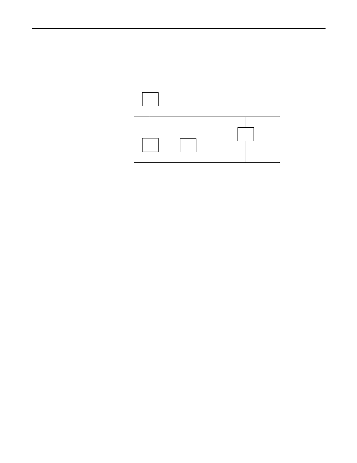
Gateway Address
A gateway connects individual physical networks into a system of networks.
When a node needs to communicate with a node on another network, a gateway
transfers the data between the two networks. The following figure shows
gateway G connecting Network 1 with Network 2.
When host B with IP address 128.2.0.1 communicates with host C, it knows
from C’s IP address that C is on the same network. In an Ethernet environment,
B can then resolve C’s IP address to a MAC address and communicate with C
directly.
When host B communicates with host A, it knows from A’s IP address that A is
on another network because the network IDs differ. To send data to A, B must
have the IP address of the gateway connecting the two networks. In this example,
the gateway’s IP address on Network 2 is 128.2.0.3.
The gateway has two IP addresses (128.1.0.2 and 128.2.0.3). Network 1 hosts
must use the first IP address, and Network 2 hosts must use the second IP
address. To be usable, a host’s gateway IP address must match its own net ID.
Devices with IP address switches use the default gateway address of either
192.168.1.1 or 0.0.0.0. Check your product information to determine which
gateway address applies for your device.
Rockwell Automation Publication ENET-RM002C-EN-P - May 2013 17
Page 18
Chapter 1 EtherNet/IP Overview
128.1.0.1
128.2.64.1
128.2.64.3
128.1.0.2
Network 1
Network 2.1
128.2.128.1 128.2.128.2
128.2.128.3
128.2.64.4
128.1.0.1
128.2.64.1
128.2.128.1
128.2.64.2
128.2.128.2
128.1.0.2
128.2.64.3
128.2.128.3
A
B
C
G
G2
DE
Network 2.2
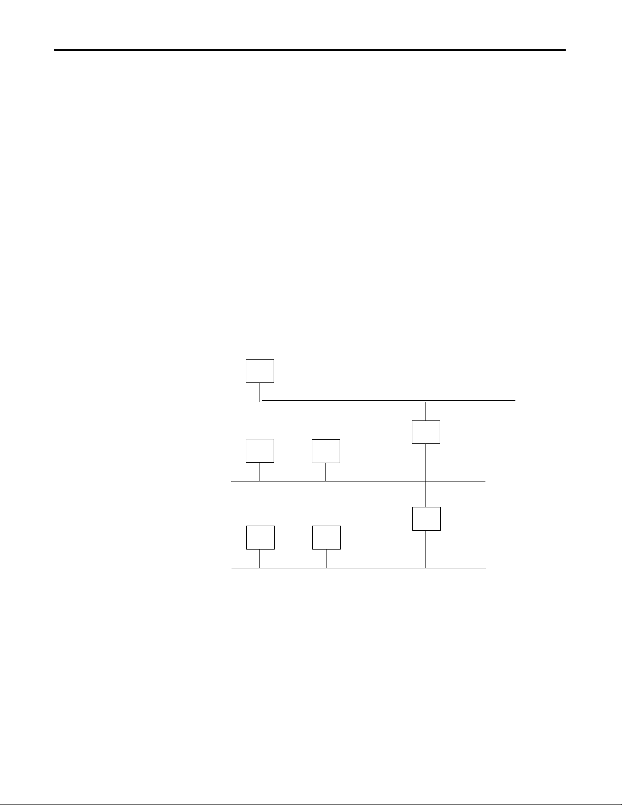
Subnet Mask
Subnet addressing is an extension of the IP address scheme. It enables a site to use
a single net ID for multiple physical networks. Routing outside of the site
continues by dividing the IP address into a net ID and a host ID via the IP class.
Inside a site, the subnet mask is used to redivide the IP address into a custom net
ID portion and host ID portion.
A subnet mask determines which of the 32 bits in the IP address are part of the
network ID and which are part of the unique node identification. This also
determines the size of the network or subnetwork.
Take Network 2 (a Class B network) in the previous example and add another
physical network. Selecting this subnet mask adds two additional net ID bits
providing for four physical networks.
11111111 11111111 11111111 00000000 = 255.255.255.0
Two bits of the Class B host ID have been used to extend the net ID. Each unique
combination of bits in the part of the host ID where subnet mask bits are 1
specifies a different physical network.
A second network with hosts D and E has been added. Gateway G2 connects
network 2.1 with network 2.2. Hosts D and E use gateway G2 to communicate
with hosts not on network 2.2. Hosts B and C use gateway G to communicate
with hosts not on network 2.1. When B is communicating with D, G (the
configured gateway for B) routes the data from B to D through G2.
18 Rockwell Automation Publication ENET-RM002C-EN-P - May 2013
Page 19
EtherNet/IP Overview Chapter 1
Switch
1756-EN2T
1756 I/O Modules
1794-AENT
1794 I/O Modules
Work stat ion
1734-AENT
1734 I/O Modules
PowerFlex®
Drive
1783-ETAP
Work stat ion
1783-ETAP
1756-EN2TR
1756 I/O Modules
1769-L18ERM-BB1B Control System
1769-L33ERM Control System
PanelView™ Plus Terminal Connected
Via a 1783-ETAP EtherNet/IP Tap
1794-AENTR FLEX™ I/O Adapter
1734-AENTR POINT I/O™ Adapter
with POINT I/O Modules
Kinetix 6500 Drives
with Motors
Kinetix 350 Drive
with Motor
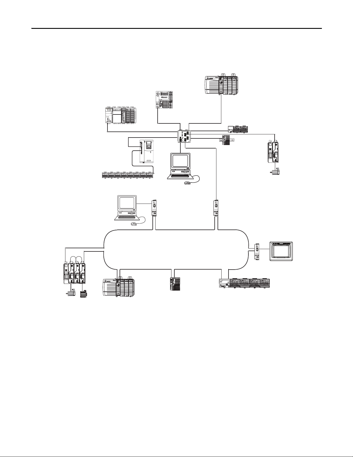
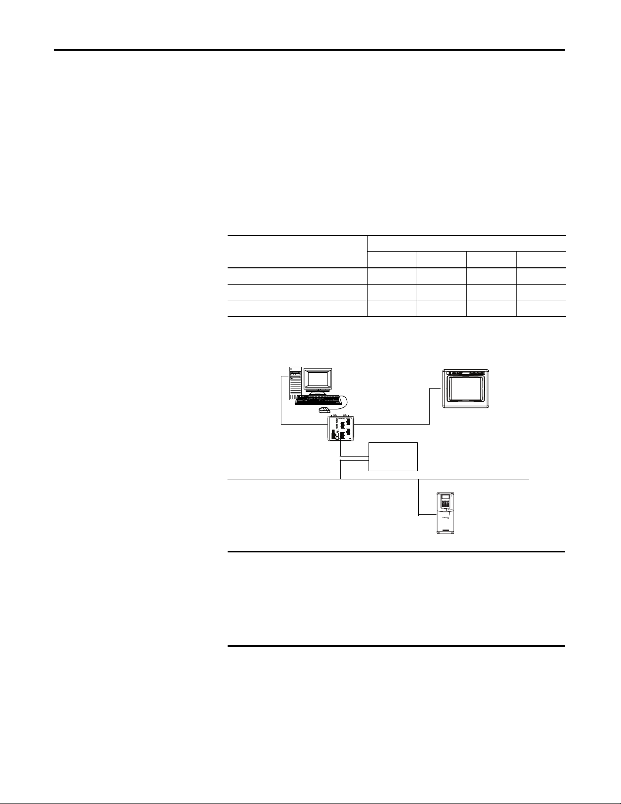
EtherNet/IP Modules in a Control System
The following diagram shows how EtherNet/IP communication modules can fit
into a control system.
In this example, the following actions can occur:
• Controllers produce and consume tags with each other.
• Controllers initiate MSG instructions to send/receive data or configure
devices.
• Controllers control I/O and drives.
• Workstations can upload/download projects to the controllers.
• Workstations can configure devices on the EtherNet/IP network.
Rockwell Automation Publication ENET-RM002C-EN-P - May 2013 19
Page 20
Chapter 1 EtherNet/IP Overview
IMPORTANT
Bridge
EtherNet/IP
Panel View Pl us
Terminal
DeviceNet
Drive
Switch
Bridge across Networks
Some EtherNet/IP communication modules support the ability to bridge or
route communication through devices, depending on the capabilities of the
platform and communication devices.
You have a bridge when you have a connection between communication devices
on two networks. For example, the bridge device has both EtherNet/IP and
DeviceNet connections, enabling Device 1 on the EtherNet/IP network to
communicate with Device 2 on a DeviceNet network through the bridge.
The bridge device can be an EtherNet/IP-to-DeviceNet bridging device or a
Logix5000 system with an EtherNet/IP communication module and a
DeviceNet communication module.
CIP messages originating on this network Can bridge to this network
EtherNet/IP ControlNet DeviceNet RS-232 Serial
EtherNet/IP Yes Yes Yes Yes
ControlNet Yes Yes Yes Yes
RS-232 Yes Yes Yes Yes
In the following example graphic, a workstation configures a drive on a
DeviceNet network and bridges EtherNet/IP networks to reach the drive.
You can bridge between devices on different networks for only messaging.
You cannot bridge from one network to another for I/O control or
produced and consumed tags. This restriction applies regardless of whether
the two networks are either of the following:
• Same type, such as an EtherNet/IP network to an EtherNet/IP network
• Different types, such as an EtherNet/IP network to a ControlNet network
20 Rockwell Automation Publication ENET-RM002C-EN-P - May 2013
Page 21

Ethernet Infrastructure Components
Top ic Pa ge
Topologies 22
Media 24
Hubs 25
Repeaters 25
Media Converters 26
Bridges 26
Routers and Gateways 27
Switche s 28
Chapter 2
The topology and cable layout of the Ethernet network is part of the physical
layer. Ethernet systems require various infrastructure components to connect
individual network segments.
Rockwell Automation Publication ENET-RM002C-EN-P - May 2013 21
Page 22
Chapter 2 Ethernet Infrastructure Components
Switch
D D D
D D
Switch
Switch
SwitchSwitch
D
D
D
D
D D
Switch
D D
Switch
D D
Switch
D D
Layer 3 Layer 3
Layer 2
D D
Layer 2
D D
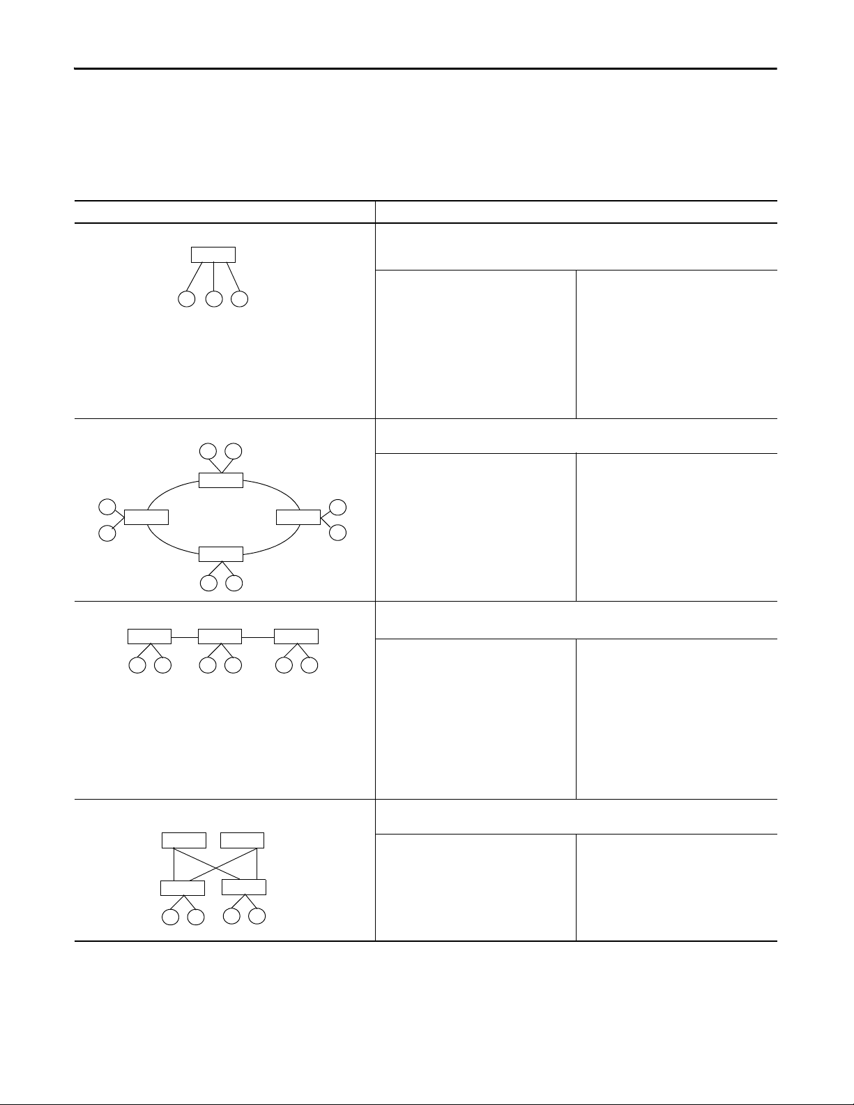
Topologies
Ethernet networks are laid out in point-to-point configurations with one cable
for each device. Ethernet networks have active infrastructures that rely on
switches. You can design a network with individual switch devices and devices
with embedded switch technology.
Table 4 - Topologies with an Individual Switch
Topology Description
Star The most common EtherNet/IP network topology is a star, where end devices are connected and
Ring—switch based A ring network is a single-fault tolerant ring network intended for the interconnection of automation
communicate with each other via a switch. In a star topology, nodes are typically grouped closely
together.
Advantag es
• Easy to design, configure, and implement
• Direct path between the infrastructure device
and the end device
• Remove and add devices without affecting the
rest of the network
• Increase port capacity on the switch to add
more devices
• Centralization can ease troubleshooting,
because the switch sees the activities of all of
the connected devices
devices.
Advantag es
• Ability to survive a single point of failure or a
device being powered down on the ring.
• Simplified cabling
• Ability to cover long distances with 100 m
between each copper segment
Disadvantages
• Loss of network service in case of connection
failure (no resiliency)
• Primarily the single point of failure of the
centralized sw itch
Disadvantages
• Additional configuration complexity
• Longer convergence times
• Variable number of hops can make
performance difficult to predict
Linear—switch based A linear network is a collection of devices that are daisy-chained together.
A linear topology works best for a limited number of nodes.
Advantag es
• Easy to design, configure, and implement
• Least amount of cabling
• Minimal amount of cable needed
• Ability to cover long distances with 100 m
between each link
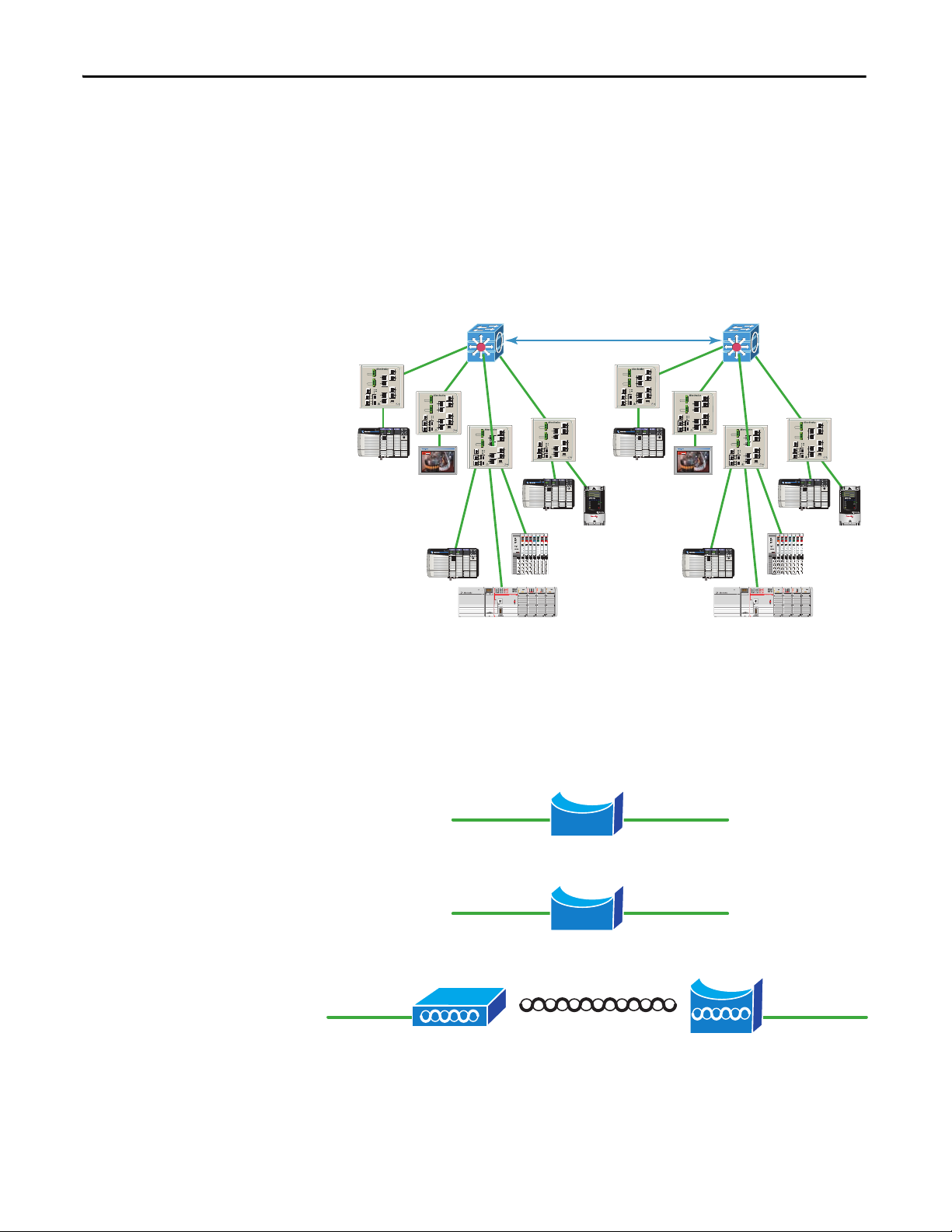
Redundant star In a redundant star topology, every Layer 2 access switch has dual connections to a Layer 3 distribution
22 Rockwell Automation Publication ENET-RM002C-EN-P - May 2013
switch. Devices are connected to the Layer 2 switches.
Advantag es
• Resiliency from multiple connection failures
• Faster convergence to connection loss
• Consistent number of hops provide
predictable and consistent per formance
• Fewer bottlenecks
Disadvantages
• Loss of network service in case of connection
failure (no resiliency)
• Creates the potential for bottlenecks
• Variable number of hops can make
performance difficult to predict
• Powering down a device or the failure of a
device in the center of the network affects
connectivity between any of the devices on
either side
• Each link in the chain represents network
delay
Disadvantages
• Additional wiring and ports required
• Additional configuration complexity
Page 23

Ethernet Infrastructure Components Chapter 2
D
D D
D
D
D
D D
The EtherNet/IP embedded switch technology offers alternative network
topologies by embedding switches into the end devices themselves.
Table 5 - Topologies with Embedded Switch Technology
Topology Description
Device-level ring (DLR)—embedded switch A DLR network is a single-fault tolerant ring network intended for the interconnection of automation devices. This
topology is also implemented at the device level. No additional switches are required.
Advantages
• Ability to survive a single point of failure or a device
being powered down on the ring.
• Simplified cabling
• Ability to cover long distances with 100 m between
Disadvantages
• Supervisor-node configuration required
• Additional configuration complexity
• Variable number of hops can make performance
difficult to predict
each copper segment
• Very fast network convergence
Linear—embedded switch A linear network is a collection of devices that are daisy-chained together. The EtherNet/IP embedded switch technology
enables this topology to be implemented at the device level. No additional switches are required.
A linear topology works best for a limited number of nodes.
Advantages
• Easy to design, configure, and implement
• Least amount of cabling
• Minimal amount of cable needed
• Ability to cover long distances with 100 m between
each link
Disadvantages
• Loss of network service in case of connection failure (no
resilie ncy)
• Creates the potential for bottlenecks
• Variable number of hops can make performance
difficult to predict
• Powering down a device or the failure of a device in the
center of the network affects connectivity between any
of the devices on either side
• Each link in the chain represents network delay
Rockwell Automation Publication ENET-RM002C-EN-P - May 2013 23
Page 24
Chapter 2 Ethernet Infrastructure Components
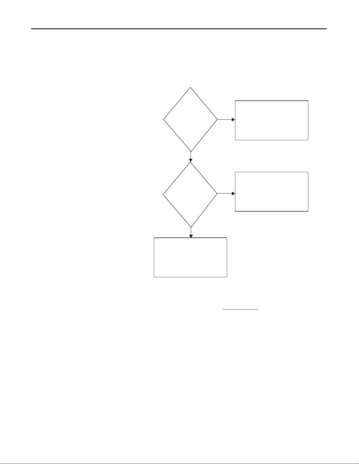
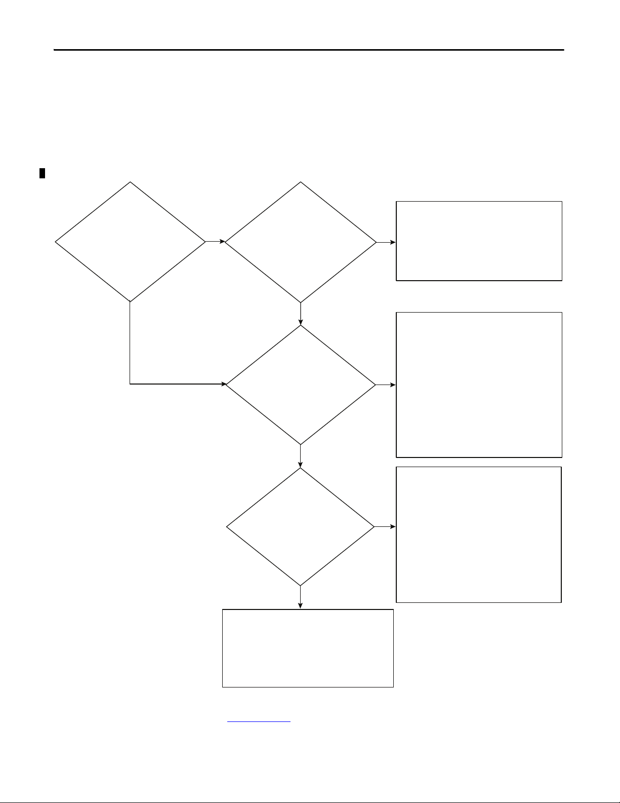
Do you have any of these:
• Long distances?
• High Magnetic fields?
• High noise?
Fiber Media
Recommendations:
• Multi-mode for general purposes, cost less
• Single-node yields higher dista nce, but
costs more
Do you have excess
amounts of any of these:
• Radiated noise?
• Conducted noise?
• Metal conduit?
Copper STP (shielded twisted pair)
Recommendations:
• Requires proper grounding
• Category 5e, 6, and 6a cables and
connectors
Copper UTP (unshielded twisted pair)
Recommendations:
• Requires proper grounding
• Category 5e, 6, and 6a cables and comectors
Yes
Yes
No
No
Media
The actual wire used for the network is referred to as the physical media.
Generally, shorter cable runs are less susceptible to EMI (electromagnetic
interference) and RFI (radio-frequency interference) from electrical circuits,
motors, and other machinery.
Figure 1 - Select Ethernet Media
For more information about the media options, see the Ethernet section of the
Network Media Catalog, publication M116-CA552
24 Rockwell Automation Publication ENET-RM002C-EN-P - May 2013
.
Page 25
Ethernet Infrastructure Components Chapter 2
Hub
HMI
1756 Controller
1734 POINT I/O
Power Flex
1738 ArmorPOINT® I/O
Personal computer
Repeater
Hubs
Hubs are multiport repeaters. They are based on older technology, which has
been largely replaced by network switches at Layer 2, but they are still used as
network diagnostic tools to analyze network traffic:
• A hub is at the center of a star topology.
• Hubs can connect together with a variety of media as a backbone between
hubs.
• A hub broadcasts everything it receives on any channel out all other
channels.
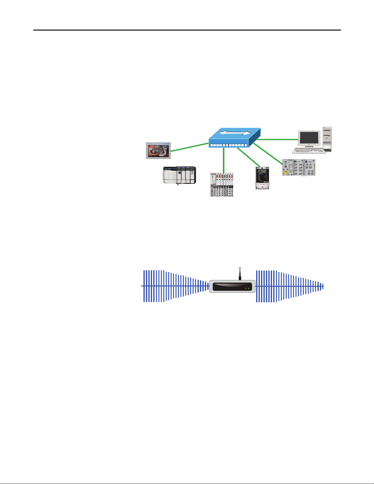
Repeaters
A repeater recreates the incoming signal and re-transmits it without noise or
distortion that can have affected the signal as it was transmitted down the cable.
Repeaters are generally used in older networks to increase the network length.
More modern networks use fiber media or switches to increase network length.
Rockwell Automation Publication ENET-RM002C-EN-P - May 2013 25
Page 26
Chapter 2 Ethernet Infrastructure Components
Fiber Link
Ethernet
Ethernet
Ethernet
Tok en R in g
Bridge
Bridge
Ethernet Ethernet
Access Poi nt
Work Group Bridge
Media Converters
Media converters let you mix fiber and copper (twisted-pair) cables in the same
system.
Use a switch to mix media:
• Physical layer devices offer no buffering or advanced diagnostic features.
• Physical layer devices are easily overrun by an EtherNet/IP system (no
buffering = lost data).
• Layer 2 devices have buffering, QoS, and other management features.
Bridges
A bridge is a device that isolates traffic between segments by selectively
forwarding frames to their proper destination. A bridge is transparent to the
network and protocol independent. More advanced devices that perform the
same bridging function are commonly used instead of a bridge.
26 Rockwell Automation Publication ENET-RM002C-EN-P - May 2013
Page 27
Ethernet Infrastructure Components Chapter 2
Routing Table
Network
Port
10.17.10.0
10.10.10.0
1
2
10.17.10.56
VLAN 17
Subnet 10.17.10.0
Subnet Mask
255.255.255.0
1
0
.
1
0
.
1
0
.
5
6
Default Gateway
10.10.10.1
10.17.10.1
VLAN 10
Subnet 10.10.10.0
Subnet Mask
255.255.255.0
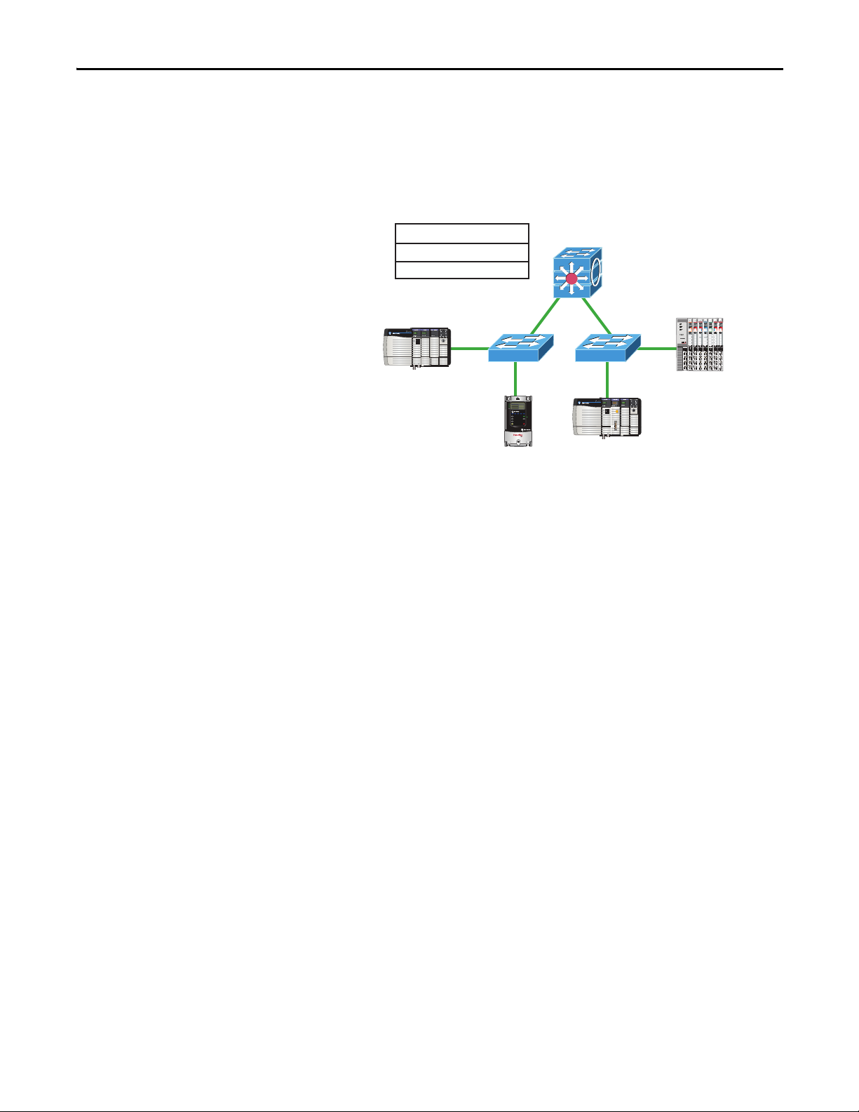
Routers and Gateways
Routers and gateways use the network portion of IP addresses to identify the
location of networks. A routing table lets a device know from which port to
transmit a message, so the message can get to a particular network. If that
network is not directly attached to the device, it forwards the message to the next
gateway or router in the path for further routing.
Rockwell Automation Publication ENET-RM002C-EN-P - May 2013 27
Page 28
Chapter 2 Ethernet Infrastructure Components
Yes
No
Yes
No
No
Do you connect to another
network infrastructure device,
such as a switch or router?
Do you ne ed Layer 3 routin g?
Select a Stratix 8300 modular, managed switch:
• 1783-RMS06T 4 ports copper, 2 ports copper/fiber
• 1783-RMS10T 8 ports copper, 2 ports copper/fiber
Optionally, add expansion ports:
• 1783-MX08T 8 ports copper
• 1783-MX08F 8 ports fiber
• 1783-MX04S 4 ports SFP
• 1783-MX08S 8 ports SFP
• 1783-MX04E 4 ports PoE
• 1783-MX4T04E 4 ports PoE + 4 ports 10/100
Select a Stratix 8000 modular, managed switch:
• 1783-MS06T
• 1783-MS10T
Optionally, add expansion ports:
• 1783-MX08T 8 ports
• 1783-MX08F 8 ports copper
• 1783-MX04S 4 ports SFP
• 1783-MX04E 4 ports PoE
• 1783-MX4T04E 4 ports PoE + 4 ports 10/100
Do you need any of these:
• Network segmentation
• Diagnostic information
• Port security
• Traffic management
• Network resiliency
Do you need any of these?
• More than 20 ports
• More than 4 fiber ports
• More than 4 PoE ports
Select a Stratix 2000™ unmanaged switch:
• 1783-US03T01F 3 ports copper, 1 port fiber
• 1783-US05T 5 ports copper
• 1783-US06T01F 6 ports copper, 1 port fiber
• 1783-US08T 8 ports copper
Select a Stratix 5700 conf igurable, managed switch:
• 1783-BMSxxx 6 port versions
• 1783-BMSxxx 10 port versions
• 1783-BMSxxx 20 port versions
Yes
No
Yes
Switches
Figure 2 - Select an Ethernet Switch
Switches provide determinism and throughput required for control applications.
Industrial-rated switches are recommended for connecting computers and other
devices to each other and to higher-level networks in the network reference
architecture. Ethernet switches perform the following:
• Operate in Full-duplex mode to eliminate collisions
• Include managed switch features for advanced network functionality
For more information, see the Stratix Switch Reference Chart, publication
ENET-QR001
.
28 Rockwell Automation Publication ENET-RM002C-EN-P - May 2013
Page 29

Ethernet Infrastructure Components Chapter 2
Unmanaged versus Managed Switches
Unmanaged switches are relatively inexpensive and simple to set up, but they do
not provide any management capabilities, security, or diagnostic information.
Therefore, they are difficult to troubleshoot.
As a general rule for unmanaged switches, make sure of the following:
• Your application does not contain I/O traffic
or
• Your application has I/O control and the following is true:
– The network is not directly connected to the IT network
– All nodes on the network are Rockwell Automation devices
– There is no potential to overload a device with traffic
Managed switches are typically more expensive than unmanaged switches and
require some level of support for initial configuration and replacement. However,
managed switches provide advanced features, which can enable better network
performance in your control system. Managed switches are able to manage
multicast traffic and provide diagnostics data, security options, and other
advanced features.
Switch Type Advantages Disadvantages
Managed • Ability to manage multicast traffic
• Diagnostics data
• Security options
• Additional advanced features
• Network segmentation features
• Network resiliency features
Unmanaged • Inexpensive
• Simple to set up
• 'No Config' replacement
• More expensive
• Requires some level of support and
configuration to start up and replace
• No network segmentation
• No dagnostic information
• No port security
• No traffic management
• No network resiliency
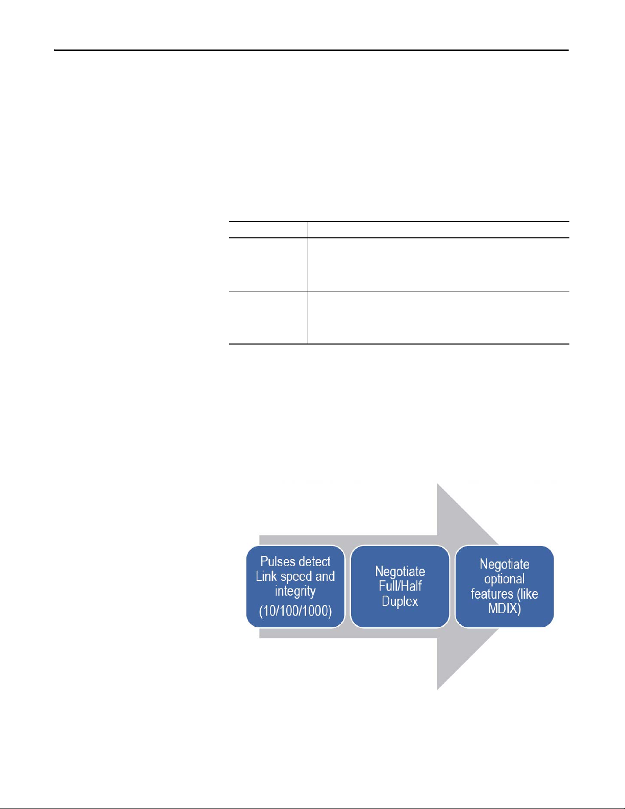
Autonegotiation
Autonegotiation lets devices select the optimal way to communicate without
requiring you to configure the devices. However, if you connect a
manually-configured device to an autonegotiation device, a high rate of data
transmission errors can occur.
All 100 Mbps devices are required to support autonegotiation, but most existing
10 Mbps devices do not. Select a switch that supports both speeds to enable you
to connect to existing devices that use the slower rate.
Rockwell Automation Publication ENET-RM002C-EN-P - May 2013 29
Page 30
Chapter 2 Ethernet Infrastructure Components
Full-duplex Mode
Ethernet is based on Carrier Sense Multiple Access/Collision Detect (CSMA/
CD) technology. This technology places all nodes on a common circuit so they
can all communicate as needed. The nodes must handle collisions (multiple
devices talking at the same time) and monitor their own transmissions so that
other nodes have transmission time.
The data transmission mode you configure determines how devices transmit and
receive data.
Tran smiss ion Mo de Featu res
Full-duplex Dete rministic
• Transmit and receive at the same time
• Transmit on the transmit pair and receive on the receive pairs
• No collision detection, backoff, or retry
• Collision free
Half- duplex Nondeterministic
• One station transmits and the others listen
• While transmitting, you do not receive, as no one else is transmitting
• If someone else transmits while you are transmitting, then a collision occurs
• Any Receive-while-Transmit condition is considered a collision
Full-duplex mode eliminates collisions. Combined with the speed of the switches
available today, you can eliminate the delays related to collisions or traffic in the
switch. A a result, the EtherNet/IP network becomes a highly deterministic
network well-suited for I/O control:
• If you are autonegotiating, make sure you verify the connection.
• If you are forcing speed and duplex on any link, make sure you force at
both ends of the link. If you force on one side of the link, the
autonegotiating side always goes to half-duplex.
30 Rockwell Automation Publication ENET-RM002C-EN-P - May 2013
Page 31

Ethernet Infrastructure Features
Top ic Page
Transmission Packets 32
Transmission Protocols 35
Network Address Translation 38
Virtual LANs and Segmentation 42
Quality of Service (QoS) 45
Resiliency 46
Internet Group Management Protocol (IGMP) 55
Port Secur ity 56
Device Commissioning 58
Chapter 3
When you use the EtherNet/IP network for time-critical control, there are
several features available in switches that are required or recommended.
Rockwell Automation Publication ENET-RM002C-EN-P - May 2013 31
Page 32

Chapter 3 Ethernet Infrastructure Features
1756 Controller
Stratix Switch
Transmission Packets
Data is transmitted over the EtherNet/IP network in packets. There are
transmission methods for transporting data on the network.
Packet Type Destination Description
Unicast A single node Unicast connec tions are point-to-point transmissions between a source node and destination node on the network.
A frame is sent to a single destination.
Multicast Multiple nodes
simultaneously
Multicast connections deliver information from one sender to multiple receivers simultaneously.
Copies of a single frame are passed to a selected subset of possible destinations.
Broadcast All nodes Broadcast connections transmit information to every device on the network.
A frame is delivered to all hosts on the network.
32 Rockwell Automation Publication ENET-RM002C-EN-P - May 2013
Page 33

Ethernet Infrastructure Features Chapter 3
Limit the amount of broadcast and multicast traffic on the supervisory control
network:
• Eliminating unwanted traffic reduces the load on devices, switches, and the
network.
• Eliminating unnecessary incoming broadcast traffic also minimizes
network load.
It is important to prevent network traffic from coming into the supervisory
control (level 2) and manufacturing operations (level 3) network from other
levels. Likewise, it is equally important to make sure that traffic on the control
system network does not get propagated into the plant enterprise network
Default Setting in the Studio 5000 Environment
The support for unicast communication and the default settings in the
Studio 5000 environment depend on the version of software. Later versions
include the unicast features of earlier versions.
Studio 5000 Version Unicast Support and Default Setting
20.01.00 Safety I/O unicast support added
Unicast default
19.01.00 Safety produce/consume unicast support added
Unicast default
18.02.00 Standard I/O unicast support added
Multicast default
16.03.00 Standard produce/consume unicast support added
Multicast default
For a compatibility chart of products see Knowledgebase answer ID 66324 at
http://www.rockwellautomation.com/knowledgebase/
.
Rockwell Automation Publication ENET-RM002C-EN-P - May 2013 33
Page 34

Chapter 3 Ethernet Infrastructure Features
Layer 2
Switch
Layer 2
Switch
I/O
(producer)
Control ler
(consumer)
Switch or
Router
To P lant Net wo rk
Frames
Use multicast frames in these situations:
• Redundancy applications
• Communication with more than one destination
Multicast is more efficient than sending multiple, unicast streams to
multiple nodes.
• Video streaming
You must use unicast communication if the transmission routes through a Layer 3
device.
I/O devices generally produce at very fast rates, such as 10 ms, so it is easy to
flood the network with multicast traffic and force each end device to spend time
deciding whether to discard numerous multicast frames. If there are a lot of I/O
devices, they can easily use up a significant part of a router’s CPU time.
You must consider control network traffic propagating onto the plant
information network, as well as, plant information network traffic propagating
onto the control network. Some best practices include the following:
• Minimize device load due to unwanted IP multicast traffic
• Minimize switch load due to unwanted IP multicast traffic
• Minimize network load due to unwanted incoming IP multicast or
broadcast traffic
• Block IP multicast traffic generated within the EtherNet/IP subnet from
propagating onto the plant network
• Implement standard network troubleshooting tools
For more information, see Virtual LANs and Segmentation
Internet Group Management Protocol (IGMP)
on page 55.
on page 42 and
34 Rockwell Automation Publication ENET-RM002C-EN-P - May 2013
Page 35

Ethernet Infrastructure Features Chapter 3
EXAMPLE
EXAMPLE
1756 Controller
1756 Controller
Device needs to send a
message to 130.151.3.4
Who has the IP address 130.151.3.4 ?
130.151.3.4
Power Flex
I have IP
address
130.151.3.4
1734 POINT I/O
Multicast Address Limit
In multicast communication, EtherNet/IP interfaces support a maximum of
32 devices that transmit multicast.
An Ethernet adapter that produces data uses a unique multicast address for
each I/O connection.
A Logix controller that produces tags uses a unique multicast address for each
produced tag.
The multicast address limit is independent of the connection limit for a device.
Not all connections require a multicast address. In the case of produced and
consumed tags, one produced tag requires one multicast address, but it also
requires one connection for each consumer. If there are multiple consumers, the
one multicast address must use multiple connections.
Transmission Protocols
The network layer (Layer 3) provides switching and routing that create logical
paths, known as virtual circuits, for transmitting data from node to node.
Routing and forwarding are functions of this layer, as well as addressing and
internetworking.
Address Resolution Protocol (ARP)
An ARP request is a broadcast message that asks ‘who has this IP address?’. The
device that has that IP address responds and the requestor adds the IP address
and hardware address pair to its ARP cache. The original device can now send the
message. This protocol enables the network to learn and adapt to changes.
Rockwell Automation Publication ENET-RM002C-EN-P - May 2013 35
Page 36

Chapter 3 Ethernet Infrastructure Features
DNS Server
What is the IP address
for the PowerFlex drive?
1756 Controller
The controller needs to
send a message to the
Power Flex dri ve.
1734 POINT I/O
PowerFlex Drive
130.151.3.4
If you replace a Rockwell Automation EtherNet/IP communication module with
a new module, the new module has a different MAC ID. The ARP cache entries
in other devices are now invalid because the MAC ID corresponding to the
module's IP address has changed. This can cause a delay in reestablishing
communication with the replacement module. The delay varies depending on the
module and the network configuration in use.
When a Rockwell Automation EtherNet/IP device starts up, it issues a gratuitous
ARP that causes other devices to update their ARP caches. This generally results
in a quick recovery of communication with the replacement module (less than a
minute). However, some switches do not forward the gratuitous ARP message
onto the network, such as if the Spanning Tree Protocol is enabled on that port.
We recommend that you disable the Spanning Tree Protocol on ports to which
EtherNet/IP communication modules are directly connected, but not on ports
that are linked to other switches. In the worst case, if the gratuitous ARP is not
seen, an originating device can wait as long as 10 minutes for the ARP cache entry
to age out and be deleted.
Domain Name System (DNS)
DNS is a name resolution protocol that enables you to identify devices by names
rather than IP addresses. For DNS to work, a DNS server is configured to hold a
table of names and the associated IP addresses. When a device attempts to send a
message to a device with an unknown name, it requests the IP address of the
named device from the DNS server.
36 Rockwell Automation Publication ENET-RM002C-EN-P - May 2013
Page 37

Ethernet Infrastructure Features Chapter 3
DNS Server
I have IP address
130.151.3.4
1756 Controller
1734 POINT I/O
PowerFlex Drive
130.151.3.4
DNS Table
Name IP Address
Controller 130.151.3.5
PowerFlex Drive 130.151.3.5
POINT I/O 130.151.3.5
The DNS server refers to its table and sends back an IP address for the requested
name. Once the client device receives the IP address for a name, it stores it in its
own table so it does not have to ask for the IP address every time. The device still
sends an ARP request if it needs to decode the IP address into a hardware address.
Rockwell Automation Publication ENET-RM002C-EN-P - May 2013 37
Page 38

Chapter 3 Ethernet Infrastructure Features
Network Address Translation
Network address translation (NAT) enables a single device to act as an agent
between the public network (commonly the plant network) and the private
network (machine network). This facilitates communication between a group of
computers with preset IP addresses on a private network by mapping each preset
IP address to a valid IP address on the public network.
These are two types of NAT implementations:
• One-to-many—Multiple nodes are mapped to a single public identity to
get onto the Internet, such as in a home network. This type of
implementation conserves public IP addresses and offers some protection
against attacks from the Internet.
• One-to-one—Each node on the network translates to another identity on
another network . This type of implementation is used in manufacturing to
integrate machinery onto a larger network without requiring addressing
changes at the machine level.
Allen-Bradley Products That Support NAT
The table summarizes features of the two products that support one-to-one NAT.
Feature 9300-ENA Device Stratix 5700 Switch
NAT architecture Standalone device Integrated into switch hardware
Performance 500 messages/s Wire-speed translations
Number of translations, max 128 128 devices or subnets
Supported network topologies Star • Star
• Redundant star
• Ring
Configuration Web interface • Device Manager Web interface
• Studio 5000 environment
• Command-line interface (CLI)
(1) One subnet translation can include translations for 16…65,000 devices.
(1)
38 Rockwell Automation Publication ENET-RM002C-EN-P - May 2013
Page 39

Supported NAT Topologies
Logix Co ntroller
Stratix 5700 with NAT
Pane lView
POINT I/O
Plant Network
PowerFlex Drive
Compac tLogix™ 5370 Controller
PanelView Plus
Stratix 2000
Kinetix 350
9300-ENA
Figure 3 - Switch-level Ring (REP) with Stratix 5700 Switch
Ethernet Infrastructure Features Chapter 3
Figure 4 - Star with 9300-ENA Device
Rockwell Automation Publication ENET-RM002C-EN-P - May 2013 39
Page 40

Chapter 3 Ethernet Infrastructure Features
Stratix 5700 with NAT
Plant Network
Logix Controller
PanelVi ew
POINT I/O
PowerFlex Drive
Stratix 5700 with NAT
Plant Network
Logix Controller
Pane lView
POINT I/O
PowerFlex Drive
Figure 5 - Star with Stratix 5700 Switch
Figure 6 - Redundant Star with Stratix 5700 Switch
40 Rockwell Automation Publication ENET-RM002C-EN-P - May 2013
Page 41

Figure 7 - Star with Device-level Ring
POINT I/O
Plant Network
1783-ETAP
Kinetix 5500 Drive
1783-ETAP
9300-ENA
or
Stratix 5700
with NAT
Pane lView
Logix Co ntroller
Ethernet Infrastructure Features Chapter 3
Rockwell Automation Publication ENET-RM002C-EN-P - May 2013 41
Page 42

Chapter 3 Ethernet Infrastructure Features
Switch
Controller 1
PC
I/O
Controller 2
I/O
I/O
I/O
I/O
VLAN 1 VLAN 2
Virtual LANs and Segmentation
A virtual LAN (VLAN) is a switched network segmented on a functional
application or organizational basis rather than a physical or geographical basis.
Switches filter destination MAC addresses and forward VLAN frames to ports
that serve the VLAN only to which the traffic belongs. A VLAN consists of
several end systems. These systems are either hosts or network equipment, such as
switches and routers, that are members of a single logical broadcast domain. A
VLAN does not have physical proximity constraints for the broadcast domain.
With VLANs, you can configure a switch to share two isolated networks without
the traffic from one network burdening the other. IP multicast traffic from
VLAN 1 does not reach VLAN 2. A VLAN blocks broadcast traffic and adds a
measure of security between networks.
A VLAN also gives you the ability to control access and security to a group of
devices independent of their physical location.
Table 6 - VLAN Features
Feature Description
Broadcast control Just as switches isolate collision domains for attached hosts and forward appropriate traffic out a particular port, VLANs
Security High-security users can be grouped into a VLAN, possibly on the same physical segment, and no users outside of that
Performance The logical grouping of devices prevents traffic on one VLAN from burdening other network resources. Performance
Network management You can logically move a device from one VLAN to another by configuring a port into a VLAN. The device does not have to
refine this concept and provide complete isolation between VLANs. A VLAN is a bridging domain, and all broadcast and
multicast traffic is contained within it.
VLAN can communicate with them. VLANs can also assist in securing plant-floor systems by limiting access of production
floor personnel, such as a vendor or contractor, to certain functional areas of the production floor.
within the VLAN is also improved because the VLAN acts as a dedicated LAN.
be physically disconnected from one network and reconnected to another, which can result in expensive,
time-consuming recabling.
Segmentation is the process of outlining which endpoints need to be in the same
LAN. Segmentation is a key consideration for a cell or area network.
Segmentation is important to help manage the real-time communication
properties of the network, and yet support the requirements as defined by the
network traffic flows. Security is also an important consideration in making
segmentation decisions.
42 Rockwell Automation Publication ENET-RM002C-EN-P - May 2013
Page 43
Ethernet Infrastructure Features Chapter 3
VLAN 10 VLAN 102 VLAN 42
A security policy can call for limiting access of factory floor personnel, such as a
vendor or contractor, to certain areas of the production floor, such as a functional
area. Segmenting these areas into distinct VLANs greatly assists in the application
of these types of security considerations.
All level 0…2 devices that need to communicate multicast I/O between each
other must be in the same LAN. The smaller the VLAN, the easier it is to manage
and maintain real-time communication. Real-time communication is harder to
maintain as the number of switches, devices, and the amount of network traffic
increase in a LAN.
Typically control networks are segmented from business networks. You can also
segment networks based on function, logical layout, and traffic types. Choose
from the following options to segment control.
Table 7 - Segment Control Options
Segmentation Option Description
Physical isolation • Physically isolate networks
ControlLogix® gateway • A separate ControlLogix EtherNet/IP bridge module is dedicated to each subnet
VLANs • Ports on a managed switch are assigned to a specific VLAN
• Each network is a separate subnet creating clusters of control
• No IT involvement
• The chassis backplane provides isolation of Ethernet traffic
• Only CIP traffic can be shared between subnets
• No IT involvement
• Data is forwarded to ports within only the same VLAN
• Can require IT involvement
Rockwell Automation Publication ENET-RM002C-EN-P - May 2013 43
Page 44

Chapter 3 Ethernet Infrastruc ture Features
802.1 Q Trunk
VLAN 102
VLAN 42
VLAN 20
VLAN 102
VLAN 42
VLAN 20
VLAN Trunking
Trunking enables a VLAN to span multiple switches.
VLANs and Segmentation Guidelines
Configure separate VLANs for different work cells or areas of your plant.
Configure one VLAN for all data traffic relevant to one particular area or cell
zone. Because 80…90% of traffic is local to one cell, this is the optimal design. All
devices with multicast connections must be on the same VLAN. Within a
VLAN, multicast and unicast traffic can be mixed depending on application
requirements. The default communication type of unicast must be used for
point-to-point communication to minimize device, network, and infrastructure
loading:
• Design small cell or area zones, each with a dedicated VLAN and IP
subnet.
• Restrict data flow out of the cell or area zone unless plantwide operations
explicitly require it.
• Segment traffic types into VLANs and IP subnets to better manage the
traffic and simplify security management.
• Within the cell or area zone, use Layer 2 VLAN trunking between
switches with similar traffic types. When trunking, use 802.1Q, VTP in
transparent mode.
• Use Layer 3 distribution switches to route information between cell or area
Zone VLANs and plantwide operations in the Industrial Zone.
• Enable IP directed broadcast on cell or area zone VLANs with
EtherNet/IP traffic for easy configuration and maintenance from control
systems, such as RSLinx® software.
• Avoid large Layer 2 networks to simplify network management.
• Select switches based on the VLAN features you need:
– Stratix 6000 switches support VLANs.
– Stratix 8000 and Stratix 8300 switches support VLANs and VLAN
trunking, as well as Layer 3 switching (enables routing across VLANs
and subnets).
44 Rockwell Automation Publication ENET-RM002C-EN-P - May 2013
Page 45

Ethernet Infrastructure Features Chapter 3
Ingress Actions Egress Actions
Classification Policing/Metering
Marking
Queue/Schedule
Congesti on Control
Distinguish traffic by
examining Layer 2/3/4
labels and QoS fields.
QoS changed depending
on trust state at port.
Make sure conformance
is to a specified rate.
DSCP-CoS or
CoS DSCP Mapping
4 queues/or with
priority scheduling
Quality of Service (QoS)
Quality of service determines how packets are marked, classified, and treated
based on traffic type. Rockwell Automation EtherNet/IP devices prioritize traffic
internally. Implementing QoS at the switch level adds another level of
prioritization. QoS does not increase bandwidth—QoS gives preferential
treatment to some network traffic at the expense of others.
Not all network traffic can be treated equally. To minimize application latency
and jitter, control data must have priority within the cell or area zone. QoS gives
preferential treatment to some network traffic at the expense of others. Control
data is more sensitive to latency and jitter than information data.
To explain how QoS works, think about the last time you boarded a plane at the
airport. As boarding time gets close, everyone starts to crowd around the gate. It
is impossible for everyone to go down the jetway to the plane at once, so the
airline establishes a boarding procedure to avoid chaos. This can be compared to
the use of QoS on an Ethernet network. The network can have motion traffic,
voice traffic, and email traffic all being transmitted at the same time over the
network.
In the airline example, first class passengers board first, followed by families with
small children, followed by frequent flyers, and followed by the coach cabin
starting at the back of the plane. Similarly, QoS lets you set up priority queues in
the managed switches on the network. In the automation example, equate
motion traffic to the first class passengers and give it the highest priority for
network usage. Voice traffic can go second (it also has low tolerance for delay),
and email traffic has the lowest priority queue. This results in the least amount of
delay possible on the motion control.
Rockwell Automation Publication ENET-RM002C-EN-P - May 2013 45
Page 46

Chapter 3 Ethernet Infrastruc ture Features
QoS Guidelines
Follow these guidelines with QoS:
• Manage the output queues based on application needs. Schedule precision
and motion control packets in the highest priority queue.
• QoS gives preferential treatment to Industrial Automation and Control
System Network traffic at the expense of other network traffic.
• QoS is integrated into the Stratix 8000 and Stratix 8300 switch
configurations.
• Deploy QoS consistently throughout Industrial Automation and Control
System Network.
Resiliency
A resiliency protocol maintains parallel links for redundancy while avoiding
loops. Network convergence time is a measure of how long it takes to detect a
fault, find an alternate path, and recover from the fault:
• During the network convergence time, some portion of the traffic is
dropped by the network because interconnectivity does not exist.
• Communication drops if the convergence time is longer than the Logix
connection timeout.
Time Calculations in a Logix5000 System
Network convergence must occur before the control system is impacted:
• Logix message instruction (MSG) time out (explicit, CIP Class 3)
• I/O connection timeout (implicit, CIP Class 1), 4 x RPI, 100 ms
minimum
• Logix Producer/Consumer connection timeout (implicit, CIP Class 1),
4 x RPI, 100 ms minimum
• Safety I/O connection timeout (implicit, CIP Class 1), 4 x RPI (default)
46 Rockwell Automation Publication ENET-RM002C-EN-P - May 2013
Page 47

Ethernet Infrastructure Features Chapter 3
Resiliency Protocols
• Spanning Tree Protocol (STP), Rapid STP (RSTP), Multiple Instance
STP (MSTP)
– Stratix 8000 and Stratix 8300–MSTP default
– Rapid Per VLAN Spanning Tree Plus (rPVST+); Cisco Technology
• Resilient Ethernet Protocol (REP); Cisco Technology
• EtherChannel Link Aggregation Control Protocol (LACP); IEEE
• Flex Links; Cisco Technology
• Device-level ring; topology option
Resiliency Protocol Mixed Vendor Ring Redundant Star Network Convergence
> 250 ms
STP X X X
RSTP X X X
MSTP X X X X
PVST+ X X X
REP X X
EtherChannel X X X
Flex Links X X X
DLR X X X
Network Convergence
> 70 ms
Network Convergence
> 1 ms
Rockwell Automation Publication ENET-RM002C-EN-P - May 2013 47
Page 48

Chapter 3 Ethernet Infrastruc ture Features
Catalyst 3750 Switch Stack
Stratix 8000
Access Sw itches
F = Forwarding
B = Blocking
B
Distribution Switches
FB F
Spanning Tree Protocol (STP) and Rapid STP (RSTP)
Spanning Tree Protocol (STP) prevents loops on the network that occur when
there is more than one open path active at once on the network. The convergence
rate can take up to 50 seconds.
Rapid Spanning Tree Protocol (RSTP) is designed for faster network
convergence and eliminates the forwarding delay on point-to-point links by using
explicit handshaking protocol. The convergence rate is significantly faster than
STP:
• Only standard protocol for network resiliency—IEEE 802.1D
• Built into Stratix 8000 and Stratix 8300 switches
• Requires redundant star or ring topology
• Provides alternate path in case of failures, avoiding loops
• Unmanaged switches do not support STP or RSTP, or any other resiliency
protocol
48 Rockwell Automation Publication ENET-RM002C-EN-P - May 2013
Page 49

Ethernet Infrastructure Features Chapter 3
Distribution Switches
Catalyst 3750 Switch Stack
FF
F
F
Stratix 8000
Access Switches
F = Forwarding
EtherChannel Protocol
The EtherChannel protocol combines multiple physical switch ports into one
logical connection to increase bandwidth through load balancing, as well as
physical connection redundancy.
This protocol groups several physical Ethernet links to create one logical
Ethernet link for the purpose of providing fault-tolerance and high-speed links
between switches, routers, and servers. An EtherChannel can combine 2…8
active Fast Ethernet or Gigabit Ethernet ports:
• Link Aggregation Control Protocol (LACP) port aggregation—IEEE
802.3ad
• Built into Stratix 8000 and Stratix 8300 switches
• Requires a redundant star topology
• Provides resiliency between connected switches if a connection is broken
Fault-tolerance is a key aspect of EtherChannel. If a link fails, the EtherChannel
technology automatically redistributes traffic across the remaining links. This
automatic recovery takes less than one second and is transparent to network
applications and the end user. This makes it very resilient.
STP can be used with an EtherChannel. STP treats all the links as a single
connection. Without the use of an EtherChannel, STP shuts down any
redundant links between switches until one connection goes down. This is where
an EtherChannel is most desirable because it enables full use of all available links
between two devices.
Rockwell Automation Publication ENET-RM002C-EN-P - May 2013 49
Page 50

Chapter 3 Ethernet Infrastruc ture Features
Distribution Switches
Catalyst 3750 Switch Stack
AS S A
Stratix 8000
Access Switches
A = Active
S = Standby
Flex Links Protocol
The Flex Links protocol provides link-level, physical redundancy in redundant
star topologies. A pair of Layer 2 switch ports are configured to act as a backup to
each other:
• Built into Stratix 8000 and Stratix 8300 switches
• Requires redundant star topology
• Active/standby port scheme
– Provides an alternate path in case of failures, avoiding loops
– No bandwidth aggregation
– Equal speed ports recommended
– Provides fast fail over for multicast traffic
50 Rockwell Automation Publication ENET-RM002C-EN-P - May 2013
Page 51

Ethernet Infrastructure Features Chapter 3
g1/1 g1/2 g1/1 g1/1 g1/1 g1/1g1/2 g1/2 g1/2 g1/2
REP Segment
Interface g1/2
REP segment 10
Interface g1/1
REP segment 10
Interface g1/2
REP segment 10
Interface g1/1
REP segment 10
Edge Por t
g1/2 Block Traffic
Edge Port
g1/2 Unblock
Link Failure
g1/1 g1/1 g1/1 g1/1 g1/1
g1/1 g1/1 g1/1 g1/1 g1/1
g1/2 g1/2 g1/2 g1/2 g1/2
g1/2 g1/2 g1/2 g1/2 g1/2
Resilient Ethernet Protocol (REP)
REP operates on chain of bridges called segments. A port is assigned to a unique
segment. A segment can have up to two ports on a given bridge. REP is built in to
Stratix 8000 and Stratix 8300 switches.
REP supports closed and open rings in various topologies:
• Redundant networks can be built with REP segments
• Only ring resiliency protocol applicable to both Industrial and IT
applications
• Ring recovery time is less than 70 ms for both unicast and multicast traffic
in fiber implementations
REP is a segment concept. A segment is a chain of bridges.
REP Segment
Interface f2
rep segment 10
Interface f1
rep segment 10
Interface f2
rep segment 10
Interface f1
rep segment 10
When all links are operational, a unique port blocks the traffic on the segment. If
any failure occurs within the segment, the blocked port goes forwarding.
Rockwell Automation Publication ENET-RM002C-EN-P - May 2013 51
Page 52

Chapter 3 Ethernet Infrastruc ture Features
Blocking
Forwarding
Forwarding
A
X
Y
B
C
A
X
Y
B
C
Link Failure
Blocking
Forwa rding
X
A
B
Y
Forwa rding
Link Failure
X
A
C
C
B
Y
Segments can be wrapped into a ring. Identification of edge ports requires
additional configuration.
Device-level Ring (DLR)
The DLR protocol is a layer 2 protocol that provides link-level, physical
redundancy that provides network convergence in the 1…3 ms range for simple
automation device networks. The other resiliency protocols apply to only
infrastructure (switches and routers). DLR provides resiliency directly to an end
device directly (such as an I/O module, drive, or controller).
Some control applications, such as safety and motion require network
convergence times faster than what switch-oriented resiliency protocols can
provide. Most control applications suffer connection timeouts with switchoriented resiliency protocols.
52 Rockwell Automation Publication ENET-RM002C-EN-P - May 2013
Page 53

Ethernet Infrastructure Features Chapter 3
Stratix 8000
IE Switch
Beacon
Beacon
Forwa rding
ControlLogix Controller
Active Ring
Supervisor
Announce AnnounceBlocking
ETAP
POINT I/O
Distributed I/O
ArmorPOINT I/O
Distributed I/O
POINT I/O
Distributed I/O
ArmorPOINT I/O
Distributed I/O
Stratix 8000
IE Switch
ETAP
Control Logix Controller
Active Ring
Supervisor
Link Failure
Link StatusLink Status
POINT I/O
Disrtributed I/O
ArmorPOINT I/O
Distributed I/O
POINT I/O
Disrtributed I/O
ArmorPOINT I/O
Distributed I/O
A DLR network is a single-fault tolerant network. Network traffic is managed to
make sure critical data is delivered in a timely manner.
Physical layer failure includes the following:
• All faults that are detectable at physical layer
• Physical layer failure detected by protocol-aware node
• Status message sent by ring node and received by ring supervisor
Rockwell Automation Publication ENET-RM002C-EN-P - May 2013 53
Page 54

Chapter 3 Ethernet Infrastruc ture Features
POINT I/O
Disrtributed I/O
ArmorPOINT I/O
Distributed I/O
POINT I/O
Disrtributed I/O
ArmorPOINT I/O
Distributed I/O
Control Logix Controller
Stratix 8000
IE Switch
1783-ETAP
Forwa rding
Active Ring
Supervisor
Forwa rding
Link Failure
\ControlLogix Controller
Active Ring
Supervisor
Forwarding
BeaconBeacon
Stratix 8000
IE Switch
ETAP
Announce Announce
Blocking
POINT I/O
Distributed I/O
ArmorPOINT I/O
Distributed I/O
POINT I/O
Distributed I/O
ArmorPOINT I/O
Distributed I/O
Network convergence includes the following:
• After failure detection, ring supervisor unblocks blocked port
• Network configuration is now a linear topology
• Fault location is readily available via diagnostics
Once ring is restored, the supervisor hears the beacon on both ports and
transitions to normal ring mode by blocking one port.
54 Rockwell Automation Publication ENET-RM002C-EN-P - May 2013
Page 55

Ethernet Infrastructure Features Chapter 3
Internet Group Management Protocol (IGMP)
The IGMP is a communication protocol used to manage the membership of IP
multicast groups. Much of EtherNet/IP implicit (I/O) messaging uses IP
multicast to distribute I/O control data, which is consistent with the CIP
produced/consumer model. Without IGMP, switches treat multicast packets the
same as broadcast packets. Multicast packets are re-transmitted to all ports.
The behavior of an unmanaged switch is to flood multicast packets to all ports
within the same VLAN. This behavior is not typically desirable. To resolve this
the following occurs:
• Querier functionality manages a table that lists the devices that are
participating in multicast groups.
• Snooping functionality inspects packets from devices and forwards
multicast data to devices that only request the data.
IGMP snooping constrains the flooding of multicast traffic by dynamically
configuring switch ports so that multicast traffic is forwarded to ports associated
with only a particular IP multicast group.
If you have a router (Layer 3 device) on the network, make it the querier. IGMP
protocol has versions 1, 2, and 3. Rockwell Automation products support
versions 1 or 2. IGMP protocol version 2 negotiates the active querier
automatically and that task is assigned to the IGMP capable device with the
lowest IP address on a given VLAN. Therefore, assign the first available IP
address on a given VLAN to the router (Layer 3 device).
If you do not have a router, the querier function must be placed on a centrally
located IGMP capable device on the network by configuring it to the first
available IP address on a given VLAN.
Rockwell Automation Publication ENET-RM002C-EN-P - May 2013 55
Page 56

Chapter 3 Ethernet Infrastruc ture Features
Port Security
The switch has dynamic and static methods for limiting the MAC addresses
(MAC IDs) that can access a given port.
Dynamic Secure MAC Address (MAC ID)
With Stratix 8000 and Stratix 8300 switches, the Smartport roles have a
maximum number of MAC IDs that can use that port. For example, the
Smartport role ‘Automation Device’ sets up the port for a maximum of one MAC
ID. The MAC ID is dynamic, meaning the switch learns the first source MAC
ID to use the port. Attempts by any other MAC ID to access the port is denied. If
the link becomes inactive, the switch dynamically relearns the MAC ID to be
secured.
Smartport Role Number of MAC IDs, max
Automation Device 1
Automation Device with QoS 1
Desktop for Automation 1
Switch for Automation Not restricted
Router Not restricted
I/P Phone + Desktop 3
Access Point Not restricted
Port Mirroring Not restricted
None Not restricted
Static Secure MAC Address (MAC ID)
With Stratix 6000, Stratix 8000, and Stratix 8300 switches, the other method of
limiting MAC IDs is to statically configure a single MAC ID for a port. MAC
IDs that communicate on a given switch port become part of the saved
configuration of the switch. This method provides strong security but requires
reconfiguration whenever the device connected to the port is replaced, because
the new device has a different MAC ID from the old device.
When you use the Studio 5000 environment to configure a Stratix 8000 and
Stratix 8300 switches, you can use the static secure method. However, this
method is not available with the Device Manager Web interface. For a
Stratix 6000 switch the port security options are configured via the web browser
or Logix5000 controller.
56 Rockwell Automation Publication ENET-RM002C-EN-P - May 2013
Page 57

Ethernet Infrastructure Features Chapter 3
Security Violations
In the event of a security violation with a Stratix 8000 or Stratix 8300 switch, one
of these situations occurs:
• The maximum number of secure MAC addresses that have been
configured for a port have been added to the address table, and a station
whose MAC address is not in the address table attempts to access the
interface.
• An address learned or configured on one secure interface is seen on
another secure interface in the same VLAN. When a violation occurs, the
port goes into the Restrict mode. In this mode, packets with unknown
source addresses are dropped and you are notified that a security violation
has occurred. An SNMP trap is sent, a syslog message is logged, and the
violation counter increments.
In the event of a security violation with a Stratix 6000 switch, the switch notifies
the controller of the event (via an input bit) and the controller program decides
how to proceed (such as shut that switch port down, send an alarm to the HMI,
or shut the machine down). The switch does not make a decision on how to
handle the security violation.
Rockwell Automation Publication ENET-RM002C-EN-P - May 2013 57
Page 58

Chapter 3 Ethernet Infrastruc ture Features
Device Commissioning
There are multiple methods for assigning IP addresses. Switches on the product,
such as thumbwheels, push buttons, or HIM modules, provide a static address
that survives power cycles.
Stratix switches support DHCP port allocation. DHCP port allocation is a
hybrid solution for IP addressing because it provides easy device replacement, but
is topology dependant.
Option Description
Static Devices are hard-coded with an IP address.
Advantage
Simple to commission and replace
Disadvantage
In large environments, can be burdensome to maintain
Static via BOOTP
configuration
DHCP A server assigns IP addresses from a pool (not recommended).
DHCP option 82 A server assigns consistent IP addresses from a pool (not recommended).
DHCP port-based
allocation
A server assigns devices an IP address.
Precursor to DHCP
Advantage
Supported by every device
Disadvantages
• Requires technician to configure IP address/MAC address when a device is replaced
• Requires a PC for commissioning and replacement (unless there are switches to set t he
address offline)
• Adds complexity and point of failure
Advantages
• Efficient use of IP address range
• Can reduce administration work load
Disadvantages
• More complex to implement and adds a point of failure
• Devices get different IP addresses when they reboot
Advantages
• Efficient use of IP address range
• Can reduce administration work load
Disadvantages
• More complex to implement and adds a point of failure
• Mixed environments do not always work
IP addresses are automatically assigned per physical switch port.
Advantages
• Efficient use of IP address range
• Eases maintenance and replacement in large environments
Disadvantage
Requires some maintenance and upkeep on a per switch basis
58 Rockwell Automation Publication ENET-RM002C-EN-P - May 2013
Page 59

EtherNet/IP Protocol
Top ic Pa ge
Conne ctions 59
EtherNet/IP Network Specifications 66
Packets Rate Capacity 69
Requested Packet Interval (RPI) 70
Messaging 71
CIP Safety 73
CIP Sync 74
Integrated Motion on an EtherNet/IP Network 76
Connectivity to IT 77
Chapter 4
Connections
The EtherNet/IP protocol is standard Ethernet and standard IP technologies
with standard CIP technology at the application layer.
EtherNet/IP communication modules must consider connections and EtherNet
nodes to communicate on the EtherNet/IP network. The number of supported
nodes applies only to CompactLogix 5370 controllers. See page 65
.
A connection is a point-to-point communication mechanism used to transfer
data between a transmitter and a receiver. Connections can be logical or physical.
Two connection types--TCP connections and CIP connections--are layered over
each other each time data is transferred. The TCP connection is the first
connection established. It is used for all EtherNet/IP communication and is
required for all CIP connection use. A single TCP connection supports multiple
CIP connections and remains open.
Established over TCP connections, EtherNet/IP CIP connections transfer data
from an application running on one end-node (transmitter) to an application
running on another end-node (receiver). CIP connections are configured to use
explicit or implicit message types. The message types support connected and
unconnected connection types. Typically, connected CIP messages are used to
transfer data. Unconnected CIP messages are used, but they are only temporary.
Rockwell Automation Publication ENET-RM002C-EN-P - May 2013 59
Page 60

Chapter 4 EtherNet/IP Protocol
TCP Connection
CIP Connection
Explicit Implicit
CIP Connection Message Types
Connected Connected
CIP Connection Types
Unconnected
You do not execute any tasks to
establish these connections.
Your decisions when configuring
your application determine the
parameters of these connections.
This graphic shows how connections are layered on each other when data is
transferred over the EtherNet/IP network.
Remember these points when configuring your EtherNet/IP network
application:
• All of the connections are used each time data is transferred on the
EtherNet/IP network.
• You specify CIP connection message types and CIP connection types
when configuring your application.
For example, when a Logix5000 controller sends a MSG instruction to
another Logix5000 controller, the transmitter sends the instruction to the
receiver over a connection. That connection includes the following:
– A TCP connection is established.
– A CIP connection is layered on the TCP connection.
– An explicit or implicit CIP connection message is delivered via the CIP
connection.
– If an explicit message type is used, it can be connected or unconnected.
If an implicit message type is used, it is connected.
• Each EtherNet/IP communication module has TCP and CIP connection
limits that you must account for when configuring your application. For
more information on connection limits, see Table 12 on page 66
• Refer toNodes on an EtherNet/IP Network
limitations for CompactLogix 5370 controllers.
on page 65 for node count
.
60 Rockwell Automation Publication ENET-RM002C-EN-P - May 2013
Page 61

EtherNet/IP Protocol Chapter 4
EXAMPLE
EXAMPLE
These example applications describe how connections are used.
I/O Connections
A Logix5000 controller has five CIP I/O connections to modules in a remote
chassis and all of these connections are through the same local 1756-EN2T
module and the same remote 1756-EN2T module.
The following connections exist:
• One TCP connection
• Five CIP connections
RSLinx OPC Test Client
The following connections exist:
• One TCP connection
• Four CIP connections (four is the default)
Terminology
The terms in this table help you understand connections.
Table 8 - EtherNet/IP Connection Terminology
Term Definition
Producer and
consumer
Client and server Client/server refers to explicit connections. A client creates a connection and initiates messages. A server provides a service or data. Clients can send
Transports Each connection has transports. A transport is a uni-directional entity with its own numeric identifier. An implicit connection has 2 transports. An explicit
UCMM In the web servers, you can see references to Unconnected Message Manager (UCMM). This type of messaging is momentary and therefore c an be ignored
Producer/consumer refers to implicit connections. With implicit connections, messages are sent cyclically (every RPI).
EXAMPLE: Assume a ControlLogix controller is controlling a single rack of FLEX I/O with a rack connection. Both the ENBT module that is local to the
controller and the FLEX AENT module are consumers and producers of data. The AENT consumes outputs and produces inputs.
messages continuously or intermittently.
EXAMPLE: A ControlLogix controller can send a MSG instruction to another controller.
connection has 1 transpor t. Transports are important because they help you calculate the number of packets per second for each Ethernet interface.
EXAMPLE: I/O
For an I/O connection to a rack of distributed I/O, a connection is confi gured in the Logix Designer appl ication by adding the communication adapter and I/O
modules in the I/O list. When the connection is created, output packets flow from the controller to the I/O rack. In addition, input packets flow from the I/O
to the controller. Each direction of flow is a transport. In this example, two transports exist. One transport is from the controller to the adapter. The second
transport is from the adapter to the controller.
EXAMPLE: Produced Tag
For a multicast produced tag connection with two consumers, there is a connection to each consumer. Data from the producer is produced to the wire on one
transport. Each of the consumers returns a heartbeat. A total of three transports exist in this example. One transport is from the tag producing controller to
the ‘wire’ media. The second transport is from one consumer to the tag producer. The third transport is from the second consumer.
unless you are troubleshooting. Examples of where UCMM messages are used are:
• Update of module firmware
• Some functions in RSLinx software
• CIP Generic MSG instruction
• Opening any CIP connection (forward_open command)
Rockwell Automation Publication ENET-RM002C-EN-P - May 2013 61
Page 62

Chapter 4 EtherNet/IP Protocol
IMPORTANT
TCP Connections
TCP connections are used for all EtherNet/IP communication and are
established before one device on the network transmits data to one or more
devices on the network. EtherNet/IP communication modules use one TCP
connection for each IP address to which the module is connected.
TCP connections are automatically established before CIP connections because
you can establish CIP connections only over a TCP connection. A single TCP
connection supports multiple CIP connections.
EtherNet/IP communication modules also have web servers that use TCP
connections for non-CIP traffic, such as HTTP. However, TCP connections used
for non-CIP traffic do not count against the limits listed above.
CIP Connections
CIP connections are automatically established over a TCP connection and
transfer data from one device on the EtherNet/IP network to another. The
following are examples of CIP connections:
• Logix5000 controller message transfer to Logix5000 controller
• I/O or produced tag
• Program upload
• RSLinx DDE/OPC client
• PanelView polling of a Logix5000 controller
There are different CIP connections.
Table 9 - CIP Connections
CIP Connection Description
Bridged A bridged connection is a connection that passes through the EtherNet/IP communication
End-node An end-node connection is a connection whose end point is the EtherNet/IP communication
Rack-optimized A rack-optimized connections is an implicit message connection to a rack or assembly object
Direct An implicit message connection from a controller to an specific I/O module (as opposed to a
module. The end point of the connection is a module other than the EtherNet/IP
communication module.
EXAMPLE: An explicit connection from a controller through a 1756-EN2T module to another
controller.
module itself.
EXAMPLE: An explicit connection from RSLinx software to the EtherNet/IP communication
module to set the module's IP address.
in the EtherNet/IP communication module. Data from selected I/O modules is collected and
produced on one connection (the rack-optimized connection) rather than on a separate
direct connection for each module.
This CIP connection is available with only digital I/O modules.
rack-optimized connection).
This CIP connection is available with analog and digital I/O modules.
62 Rockwell Automation Publication ENET-RM002C-EN-P - May 2013
Page 63

EtherNet/IP Protocol Chapter 4
IMPORTANT
CIP connections are further defined by these additional connection
parameters:
• CIP Connection Message Types
• CIP Connection Types
CIP Connection Message Types
CIP connections use one of the following CIP connection message types:
• Implicit
• Explicit
Implicit connections are time critical in nature. This includes I/O and
produced/consumed tags. Implicit refers to information (such as source address,
data type, or destination address) that is implied in the message but not
contained in the message.
Explicit connections are non-time critical and are request/reply in nature.
Executing a MSG instruction or executing a program upload are examples of
explicit connections. Explicit refers to basic information (such as source address,
data type, or destination address) that is included in every message.
CIP Connection Types
CIP connection types determine how CIP connections transfer data on the
network. The CIP connection types determine whether a connection is
established between devices. If a connection is established between devices, the
connection type determines if that connection remains open after data is
transferred.
There are two CIP connection types:
• Connected—Available with both implicit and explicit messages.
• Unconnected—Available with only explicit messages.
Ta b l e 1 0
messages.
describes how CIP connections are used with implicit and explicit
Rockwell Automation Publication ENET-RM002C-EN-P - May 2013 63
Page 64

Chapter 4 EtherNet/IP Protocol
Table 10 - CIP Connections with Implicit and Explicit Messages
CIP Connection Type As Used with Implicit Messages As Used with Explicit Messages
Connected The following events occur:
1. A connection is established between devices.
2. Data is transferred between devices.
3. The connection remains open for future data transmission.
The following are examples of connected implicit messaging:
• I/O data transfer
• Produced/consumed tags between Logix5000 controllers
Keep in mind the following points for connected implicit messaging:
• Execution time is more efficient because the CIP connection between
devices does not need to be reopened for each data transfer.
• EtherNet/IP communication modules support limited numbers of CIP
connections. Because this connection remains open all the time, there is
one fewer CIP connection available for other data transfer through the
module.
Unconnected N/A In unconnected explicit messaging, no conne ction is established between
The following events occur:
1. A connection is established between devices.
2. Data is transferred between devices.
3. The connection between the devices is closed.
If data needs to be transferred again between these same two device,
the connection must be reopened.
The following are examples of connected explicit messaging:
• MSG instruction
• RSLinx Classic software setting the IP address for an EtherNet/IP
communication module
If you select a cached connection, the connection is not closed at the end of
the transaction.
Keep in mind the following points for connected explicit messaging:
• Execution time is less efficient because the CIP connection between
devices must be reopened for each data transfer.
• EtherNet/IP communication modules support limited numbers of CIP
connections. Because this CIP connection is closed immediately after use,
the CIP connection is immediately available for other data transfer
through the module.
devices.
Data is sent in a packet that includes destination identifier information in
the data structure but does not have a dedicated connection.
64 Rockwell Automation Publication ENET-RM002C-EN-P - May 2013
Page 65

EtherNet/IP Protocol Chapter 4
IMPORTANT
Nodes on an EtherNet/IP Network
This section applies to only CompactLogix 5370 controllers. For most
applications, proceed to Table 12 on page 66
CompactLogix 5370 controllers use the number of Ethernet nodes to stay within
their capacity for the number of connections. These controllers have limits on the
number of nodes they support in the I/O configuration within your controller
project.
Any devices you add directly to the local Ethernet node in the I/O configuration
are counted toward the controller’s node limitation. The following are example
devices that are added to the I/O configuration and must be counted:
• Remote communication adapters
• I/O modules directly connected to the EtherNet/IP network, for example
the 1732E-IB16M12R ArmorBlock® EtherNet/IP module
• Motion devices, such as drives
for network specifications.
You do not count Ethernet devices that exist on the EtherNet/IP network but are
not added to the I/O configuration. These devices include the following:
• Computer
• HMI that are not added to the I/O configuration section, for example,
PanelView Plus terminals
• MSG instructions that do not use an RPI and are not time-critical
• Devices that communicate via a socket interface, such as
CompactLogix 5370 controllers
Table 11 - CompactLogix 5370 Controller Ethernet Node Guidelines
Cat. No. Ethernet Nodes Supported
1769-L16ER-BB1B 4
1769-L18ER-BB1B
1769-L18ERM-BB1B
1769-L24ER-QB1B
1769-L24ER-QBFC1B
1769-L27ERM-QBFC1B
1769-L30ER
1769-L30ERM
1769-L30ER-NSE
1769-L33ER
1769-L33ERM
1769-L36ERM 48
8
16
32
For more information, see the CompactLogix 5370 Controllers User Manual,
publication 1769-UM021
Rockwell Automation Publication ENET-RM002C-EN-P - May 2013 65
.
Page 66

Chapter 4 EtherNet/IP Protocol
EtherNet/IP Network Specifications
Table 12 - EtherNet/IP Network Specifications
Cat. No. Connections CIP Unconnected
TCP CIP I/O HMI and MSG
Messages
(backplane +
Ethernet Node
Count, Max
Packet Rate Capacity (packets/second)
Ethernet)
1734-AENT, 1734-AENTR 32 20 32 N/A 5000 900 No
1738-AENT, 1738-AENTR 32 20 32 N/A 5000 900 No
64
128
(3)
64 + 64 N/A 5000 900 Yes
(3)
128 + 128 N/A IMPORTANT: Packet rates for
(3)
128 + 128 N/A 2000 Yes
(3)
128 + 128 N/A 2000 Yes
(3)
128 + 128 N/A 2000 Yes
(3)
128 + 128 N/A 2000 Yes
(3)
128 + 128 N/A 930 with encryption
(3)
128 + 128 N/A 2000 Yes
(3)
128 + 128 N/A N/A 900 Yes
(3)
32 + 32 N/A 5000 960 Yes
(3)
32 + 32 N/A 2000 380 Yes
(3)
32 + 32 N/A 4000 760 Yes
ControlLogix EtherNet/IP
communication modules depend
on series and firmware revision.
See Table 14 on page 68.
1756-ENBT 64 128
1756-EN2F 128 256
1756-EN2T 128 256
1756-EN2TXT 128 256
1756-EN2TR 128 256
1756-EN2TRXT 128 256
1756-EN2TSC 128 256
1756-EN3TR 128 256
1756-EWEB 64 128
1768-ENBT 32
(1)
(2)
64
1769-L23Ex 832
1769-L3xE6432
1769-L16ER-BB1B 120 256 256 4 6000 @ 500 bytes/packet 400 messages/s @ 20%
1769-L18ER-BB1B 120 256 256 8 6000 @ 500 bytes/packet Yes
1769-L18ERM-BB1B 120 256 256 8 6000 @ 500 bytes/packet Yes
1769-L24ER-QB1B 120 256 256 8 6000 @ 500 bytes/packet Yes
1769-L24ER-QBFC1B 120 256 256 8 6000 @ 500 bytes/packet Yes
1769-L27ERM-QBFC1B 120 256 256 16 6000 @ 500 bytes/packet Yes
1769-L30ER 120 256 256 16 6000 @ 500 bytes/packet Yes
1769-L30ERM 120 256 256 16 6000 @ 500 bytes/packet Yes
1769-L30ER-NSE 120 256 256 16 6000 @ 500 bytes/packet Yes
1769-L33ER 120 256 256 32 6000 @ 500 bytes/packet Yes
1769-L33ERM 120 256 256 32 6000 @ 500 bytes/packet Yes
1769-L36ERM 120 256 256 48 6000 @ 500 bytes/packet Yes
1783-ETAP 64 N/A N/A N/A N/A 900 No
1783-ETAP1F, 1783-ETAP2F 64 N/A N/A N/A N/A 900 No
1794-AENT 64 64 N/A N/A 9500 N/A Yes
2x-COMM-E 30 16 16 N/A 400 50 No
9300-ENA N/A N/A N/A N/A — — N/A
(4)
2000 Yes
1800 without encryption
comm. timeslice
SNMP Support
(password
required)
Yes
Yes
(1) The 1768-ENBT communication module supports 32 TCP connections with firmware revision 1.x.
(2) The 1768-ENBT communication module supports 64 TCP connections with firmware revision 2.x or later.
(3) CIP connections can be used for all explicit or all implicit applications. For example, a 1756-ENBT module has a total of 128 CIP connections that can be used for any combination of connections.
(4) Total packet rate capacity = I/O Produced Tag, max + HMI/MSG, max. Packet rates vary depending on packet size. For more detailed specifications, see the EDS file for a specific catalog number.
66 Rockwell Automation Publication ENET-RM002C-EN-P - May 2013
Page 67

Table 13 - EtherNet/IP Network Specifications
EtherNet/IP Protocol Chapter 4
Cat. No. Media Support Produced/Consumed Tags Socket
Twisted Pair
1734-AENT, 1734-AENTR Yes
1738-AENT, 1738-AENTR Yes
1756-ENBT Yes
(1)
Fiber Number of
(2)
(2)
(2)
No N/A Version 18.02.00 or later No N/A Revision 2.x - 1734-AENT
No N/A Version 18.02.00 or later No N/A Revision 2.x - 1738-AENT
No 32
1756-EN2F No Yes 32
1756-EN2T Yes
1756-EN2TXT Yes
1756-EN2TR Yes
1756-EN2TRXT Yes
1756-EN2TSC Yes
1756-EN3TR Yes
1756-EWEB Yes
1768-ENBT Yes
1768-EWEB Yes
1769-L23Ex Ye s
1769-L3xEYes
1769-L16ER-BB1B Yes
1769-L18ER-BB1B Yes
1769-L18ERM-BB1B Yes
1769-L24ER-QB1B Yes
1769-L24ER-QBFC1B Yes
1769-L27ERM-QBFC1B Yes
1769-L30ER Yes
1769-L30ERM Yes
1769-L30ER-NSE Yes
1769-L33ER Yes
1769-L33ERM Yes
1769-L36ERM Yes
1783-ETAP Yes
1783-ETAP1F, 1783-ETAP2F Yes
1794-AENT Yes
2x-COMM-E Yes
9300-ENA Yes
(2)
(2)
(2)
(2)
(2)
(2)
(2)
(2)
(2)
(2)
(2)
(2)
(2)
(2)
(2)
(2)
(2)
(2)
(2)
(2)
(2)
(2)
(2)
(2)
(2)
(2)
(2)
(2)
No 32
No 32
No 32
No 32
No 32
No 32
No N/A N/A Yes N/A Revision 2.2
No 32
No N/A N/A Yes N/A Revision 1.x
No 32
No 32
No 32 multicast produced
No Yes Yes N/A Revision 20.x
No Yes Yes Up to 2 axes Revision 20.x
No Yes Yes N/A Revision 20.x
No Yes Yes N/A Revision 20.x
No Yes Yes Up to 4 axes Revision 20.x
No Yes Yes N/A Revision 20.x
No Yes Yes Up to 4 axes Revision 20.x
No Yes Yes N/A Revision 20.x
No Yes Yes N/A Revision 20.x
No Yes Yes Up to 8 axes Revision 20.x
No Yes Yes Up to 16 axes Revision 20.x
No N/A N/A No N/A Revision 1.x
Yes N/A N/A No N/A Revision 2.x
No N/A N/A No N/A Revision 3.x
No N/A N/A No N/A Revision 1.1
No N/A N/A N/A N/A N/A
Multicast Tags, Max
(3)
(3)
(3)
(3)
(3)
(3)
(3)
(3)
(3)
(3)
(3)
(3)
tags
128 unicast produced
tags
Unicast Available in
RSLogix 5000 Software
Version 16.03.00 or later No See Ta ble 14 o n
Version 16.03.00 or later Yes Revision 1.x
Version 16.03.00 or later Yes Revision 1.x
Version 16.03.00 or later Yes Revision 1.x
Version 17.01.02 or later Yes Revision 1.x
Version 20.01.00 or later Yes Revision 1.x
Version 20.01.00 or later Yes Revision 1.x
Version 18.02.00 or later No Revision 3.x
Version 16.03.00 or later No N/A Revision 1.x
Version 17.01.02 or later No N/A Revision 16
Version 16.03.00 or later No N/A Revision 15
Yes Yes N/A Revision 20.x
Services
Integrated Motion
on the EtherNet/IP
Network Axes
page 68.
Duplicate IP Detec tion
(starting revision)
Revision 3.x - 1734-AENTR
Revision 3.x - 1738-AENTR
Revision 3.3
(1) Most modules listed, with the exception of three fiber modules, support a speed duplex of 10/100. The 1756-EN2F, 1783-ETAP1F, and 1783-ETAP2F modules have a speed duplex of 100.
(2) Module has two ports instead of one. With the second port, you can wire the module directly into a linear or device-level ring topology instead of connecting the network devices with an external
managed switch. For more information on Embedded Switch Technology, see the EtherNet/IP Embedded Switch Technology Ap plication Guide, publication ENET-AP005.
(3) Each controller can send a maximum of 32 produced tags to one single consuming controller. If these same tags are sent to multiple consumers, the maximum number is 31.
Rockwell Automation Publication ENET-RM002C-EN-P - May 2013 67
Page 68

Chapter 4 EtherNet/IP Protocol
Table 14 - Additional ControlLogix EtherNet/IP Communication Module Specifications
Cat. No. Series Firmware
Revision
RSLogix 5000
Software Version
RSLinx Software
Versi on
Packet Rate Capacity (packets/ second)
I/O HMI/MSG
1756-ENBT Any Any 8.02.00 or later 2.30 or later 5000 900 No N/A
1756-EN2F A 2.x 15.02.00 or later 2.51 or later 10,000 2000 No N/A
3.6 or later 18.02.00 or later
(1)
25,000
(3)
B Up to 8 axes
1756-EN2T A 2.x or earlier 15.02.00 or later 2.51 or later 10,000 2000 No N/A
3.6 or later 18.02.00 or later
(1)
25,000
(3)
B2.x 15.02.00 or later 10,000 N/A
3.6 or later 18.02.00 or later
(1)
25,000
(3)
C Up to 8 axes
1756-EN2TXT B 2.x 15.02.00 or later 2.51 or later 10,000 2000 Yes N/A
3.6 or later 18.02.00 or later
(1)
25,000
(3)
C Up to 8 axes
1756-ENT2TR A 2.x 17.01.02 or later 2.55 or later 10,000 2000 No N/A
3.6 or later 18.02.00 or later
(1)
2.56 or later 25,000
(3)
B Up to 8 axes
1756-EN2TRXT A 5.028 or later 20.01.00 or later 2.56 or later 25,000
1756-EN2TSC A 5.028 or later 20.01.00 or later 2.56 or later 25,000
(3)
(3)
2000 Yes N/A
930 with encryption
1800 without encryption
1756-EN3TR A 3.6 or later 18.02.00 or later
(1)
2.56 or later 25,000
(3)
2000 No Up to 255 axes
9300-ENA A 1.12 or later N/A N/A N/A — No N/A
(2)
Support for
Extended
Environment
No N/A
(4)
Integrated Motion
on the EtherNet/IP
Network Axes
Up to 4 axes
(5)
supported
(5)
supported
Up to 4 axes
(5)
supported
Up to 4 axes
(5)
supported
(5)
supported
Up to 4 axes
(5)
supported
(5)
supported
Up to 4 axes
(5)
supported
(5)
supported
(5)
supported
(1) This version is required to use CIP Sync technology, Integrated Motion on the EtherNet/IP Network, or Exact Match keying.
(2) For more information on Packet Rate Capacity, see Packets Rate Capacity
(3) The packet rate capacity can change slightly depending on the firmware revision of your EtherNet/IP communication module. For more information, see Packet s Rate Cap acity
(4) Module operates in a broad temperature spectrum, -20…70 ºC (-4…158 ºF), and meets ANSI/ISA-S71.04-1985 Class G1, G2 and G3, as well as cULus, Class 1 Div 2, C-Tick, CE, ATEX Zone 2 and SIL 2
requirements for increased protection against salts, corrosives, moisture/condensation, humidity, and fungal growth.
(5) This value assumes the use of a 1756-L7x ControlLogix controller. For a 1756-L6x ControlLogix controller, see ControlLogix Controllers User Manual, publication 1756-UM001
on page 69.
on page 69.
.
68 Rockwell Automation Publication ENET-RM002C-EN-P - May 2013
Page 69

EtherNet/IP Protocol Chapter 4
IMPORTANT
IMPORTANT
Packets Rate Capacity
Beginning with firmware revision 3.x for ControlLogix EtherNet/IP
communication modules, packet rate capacity is increased.
Connection size impacts a module’s increased packet rate capacity gained with
firmware revision 3.x or later.
Smaller connections are processed faster than larger connections. Larger
connections can affect the increased packet rate capacity obtained with
firmware revision 3.x or later. These type of applications use larger connections:
• Applications with rack-optimized connections
• Applications with Integrated Motion on the EtherNet/IP network
• Applications with large produce/consume tag arrays
Modules with firmware revision 3.x or later always have greater packet
rate capacity than modules with firmware revision 2.x or earlier in the same
application. Larger connections impact only how much greater the packet rate
capacity is with firmware revision 3.x or later.
EtherNet/IP Capacity Tool
The EtherNet/IP Capacity Tool is intended to help you in the initial layout of
your EtherNet/IP network by calculating resources, for example, connections,
packet rate capacity, used by a proposed network.
Download the EtherNet/IP Capacity Tool at the Integrated Architecture Tools
website. http://www.rockwellautomation.com/solutions/
integratedarchitecture/resources3.html#enetpredict
The EtherNet/IP Capacity Tool calculates a rough estimate of the packet rate
capacity. Packet rate capacity varies depending on the specific conditions of
each application.
For a more detailed analysis of a proposed network, use RSNetWorx™ for
EtherNet/IP software.
Rockwell Automation Publication ENET-RM002C-EN-P - May 2013 69
Page 70

Chapter 4 EtherNet/IP Protocol
Upgrade to Latest Firmware Revision
All ControlLogix EtherNet/IP communication modules must be upgraded to
firmware revision 3.x or later to increase their packet rate capacity. You can
upgrade your module’s firmware regardless of series.
Download the latest firmware revisions at the Rockwell Automation technical
support website. http://support.rockwellautomation.com/ControlFlash/
Monitor Packet Sizes in Current Application
Some EtherNet/IP communication modules offer web pages that show module
and application information. To view your module’s information, type the
module’s IP address into your web browser.
For more information on packet rate capacity on ControlLogix EtherNet/IP
communication modules, see Article ID 66326, ControlLogix 1756-ENxxx V3.x
performance increase FAQ, available from the Rockwell Automation
Knowledgebase at http://www.rockwellautomation.com/support/americas/
index_en.html.
Requested Packet Interval (RPI)
The RPI is the update rate specified for a particular piece of data on the network.
The RPI can be specified for an entire rack via a rack-optimized connection or for
a particular module via a direct connection.
When adding a module to the I/O configuration of a controller, you must
configure the RPI. This value specifies how often to produce the data for that
module. For example, if you specify an RPI of 50 ms, every 50 ms the I/O module
sends its data to the controller or that the controller sends its data to the I/O
module.
RPIs are used for only implicit connections, such as produced/consumed tags
and I/O. For example, a local EtherNet/IP communication module does not
require an RPI because it does not produce data for the system but acts as a bridge
to remote modules.
Set the RPI only as fast as needed by the application. The CompactLogix 5370
controllers always attempt to scan an I/O module at the configured RPI rate. For
guidelines on setting the RPI for the CompactLogix 5370 controllers, see the
CompactLogix 5370 Controllers User Manual, publication 1769-UM021
The RPI also determines the number of packets per second that the module
produces on a connection. Each module has a limit on the total number of
implicit packets per second. The total includes the sum of sent and received
implicit packets. The packet rate capacity for implicit messages is for only
implicit packets and neither matches nor includes the explicit packet rate
capacity.
.
70 Rockwell Automation Publication ENET-RM002C-EN-P - May 2013
Page 71

EtherNet/IP Protocol Chapter 4
Messaging
The EtherNet/IP network supports both time-critical (implicit) and non timecritical (explicit) message transfer services of CIP. Exchange of time-critical
messages is based on the producer/consumer model where a transmitting device
produces data on the network and many receiving devices can consume this data
simultaneously.
Implicit Messages
Implicit messages are time critical in nature. This includes I/O and produced/
consumed tags. Implicit refers to information (source address, data type, and
destination address) that is implied in the message, but not contained in the
message. Examples of implicit applications include the following:
• Real-time I/O data
• Functional safety data
• Motion control data
Implicit messages use the User Datagram Protocol (UDP) and can be unicast or
multicast. Implicit messages transport data via transport class 0/1 (Class 1):
• The data source/destination is an application object (assembly object).
• There is no protocol in the message data—it is all I/O data.
• Data transfer is more efficient because the meaning of the data is known
ahead of time.
• Transfer is initiated on a time basis (cyclic trigger) or requested packet
interval (RPI).
• There is a connection timing mechanism to alert the application if the
other side has stopped communicating.
• Messaging is always connected—there are is unconnected implicit
messaging.
An implicit message times out in controller_multiplier x RPI. The multiplier is
selected by the controller firmware so that the timeout is greater than or equal to
100 ms. The minimum multiplier is 4.
These are examples:
• RPI = 2 ms; controller multiplier = 64. The timeout is 128 ms.
• RPI = 10 ms; controller multiplier = 16. The timeout is 160 ms.
Rockwell Automation Publication ENET-RM002C-EN-P - May 2013 71
Page 72

Chapter 4 EtherNet/IP Protocol
Explicit Messages
Explicit connections are non-time critical and are request/reply in nature.
Executing a MSG instruction or executing a program upload are examples of
explicit connections. Explicit refers to basic information (such as source address,
data type, or destination address) that is included in every message. Each request
is typically directed at a different data item. Examples of explicit applications
include the following:
• HMI
• RSLinx connections
• Message (MSG) instructions
• Program upload/download
Explicit messages use Transmission Control Protocol (TCP). Explicit messages
are used for point-to-point, client-server transactions that use transport class 3
(Class 3):
• The server side is bound to the Message Router object and has access to all
internal resources.
• The client side is bound to a client application object and must generate
requests to the server.
• Explicit messages use an explicit messaging protocol in the data portion of
the message packet.
Application
Object
• Explicit messages can be connected or unconnected.
Device #1 Device #2
Request
Response
Explicit
Messaging
Connection
Explicit
Messaging
Connection
Request
Response
Application
Object
An explicit message times out in 30 seconds. This is user-changeable in the
Message (MSG) instruction structure.
72 Rockwell Automation Publication ENET-RM002C-EN-P - May 2013
Page 73

EtherNet/IP Protocol Chapter 4
Stratix
1791ES
Guard I/O™
1768 Compact GuardLogix®
Camera POINT Guard I/O™
POINT Guard I/O
1783-ETAP
HMI
1738 ArmorPOINT I/O
Stratix
Stratix
1783-ETAP
1756 GuardLogix
1734 POINT I/O
1783-ETAP
Power Flex
1794 FLEX I/O
1768 CompactLogix
CIP Safety
CIP Safety is an extension to the application layer that provides a set of highly
integrated safety services that leverage the underlying communication stacks of
the standard CIP networks to transport data from a source to a destination. CIP
Safety is certified to be compliant with the functional safety standard IEC 61508
up to safety integrity level (SIL) 3.
The CIP Safety end-to-end protocol gives responsibility to ensuring safety to the
end nodes—rather than the bridges, routers, or intermediate nodes. CIP Safety
cannot prevent communication errors from occurring, but if an error does occur
in the transmission of data or in the intermediate router, the end device detects
the failure and takes the appropriate action. Because the safety coding and not the
underlying communication layers enforce the integrity of the data, the underlying
communication layers can be interchanged and intermixed even across subnets.
CIP Safety lets you mix standard and safety devices on the same open network.
Rockwell Automation Publication ENET-RM002C-EN-P - May 2013 73
Page 74

Chapter 4 EtherNet/IP Protocol
Time Mas ter Time Slave
Time Slave
Time Slave
CIP Sync
CIP Sync defines time synchronization services for CIP. Time synchronization
on the EtherNet/IP network is a method to synchronize clocks across devices on
the network. In a synchronized application, there is a single time master and
multiple time slaves. For example, a ControlLogix controller can be configured to
act as the time master and other ControlLogix modules, connected via
EtherNet/IP communication modules, serve as the time slaves.
You can synchronize the clocks within the following applications:
• Multiple ControlLogix controllers
• ControlLogix redundancy systems
• Real world clocks
• Personal computer-based events
74 Rockwell Automation Publication ENET-RM002C-EN-P - May 2013
Page 75

EtherNet/IP Protocol Chapter 4
Typical time synchronized applications include the following:
• Input time stamping
– Events and alarms
– Sequence of Events recording
– First fault detection
• Time scheduled outputs
• Integrated motion on EtherNet/IP drive synchronization
• Distributed motion control
CIP Sync a time synchronization extension to the application layer can help solve
these application requirements. CIP Sync is based on the IEEE 1588 (IEC
61588) standard—Precision Clock Synchronization Protocol for Networked
Measurement and Control Systems, commonly referred to as the Precision Time
Protocol (PTP). The protocol provides a standard mechanism to distribute
Coordinated Universal Time (UTC) across a standard Ethernet network of
distributed devices. By time stamping in UTC events can easily be compared
across time zones without having to be adjusted for the geography in which they
were generated.
CIP Sync lets users base control on true time synchronization rather than the
more limited event synchronization model used historically. In a 100 Mbps
switched Ethernet system, advanced testing shows CIP Sync can deliver time
synchronization accuracy of less than 500 ns between devices, meeting the
requirements of some of the most demanding real-time applications.
Rockwell Automation Publication ENET-RM002C-EN-P - May 2013 75
Page 76

Chapter 4 EtherNet/IP Protocol
1791ES Guard I/O
Stratix
1768 Compact GuardLogix
Camera
Stratix
Stratix
POINT Guard I/O
1756 Controller
1783-ETAP
1783-ETAP
1783-ETAP
Power Flex
1756 Controller
Kinetix
1734 POINT I/O
Kinetix
1738 ArmorPOINT I/O
Integrated Motion on an EtherNet/IP Network
Integrated motion on an EtherNet/IP network sets the EtherNet/IP
networking technology apart from the other industrial Ethernet networks.
EtherNet/IP modules with integrated motion on the EtherNet/IP network
combine the requirements of deterministic real-time motion control applications
with standard unmodified Ethernet that provides full compliance with the
Ethernet standards IEEE 802.3 and TCP/IP. This supports the use of standard
Ethernet components and infrastructure without the use of special switches or
gateways.
Integrated Motion on the EtherNet/IP network accomplishes this by
encompassing a set of application profiles that let position, speed, and torque
loops to be set in the drive. With the addition of the CIP Sync technology
multiple axes can be coordinated for precise, coordinated motion control
applications.
Integrated motion on the EtherNet/IP network uses time-stamped data along
with its simple timing model to eliminate hard synchronization constraints
between the drive and the controller. Real-time data values are adjusted at the end
device at the time the data is applied; no need to hard schedule the network
traffic.
In addition, integrated motion on the EtherNet/IP network has the flexibility to
handle different types of drives and time synchronization requirements. The
same network connection can be used for both a high performance servo drive
with precise synchronization requirements, and a low performance Volts/Hertz
drive with no time synchronization capability.
76 Rockwell Automation Publication ENET-RM002C-EN-P - May 2013
Page 77

EtherNet/IP Protocol Chapter 4
Enterprise Business Systems
Level 4
Data Center
IT Network
Industrial Network
Level 3 - Site Operations
• FactoryTalk® Application Servers
• FactoryTalk Services Platform
• Data Servers
DIO
DIO
DIO
Drive
Controlle r
HMI
HMI
Drive
Camera
Control ler
Control ler
Drive
HMI
Stratix 8000
Layer 2 Switch
Filling Cell/Area Zone
Levels 0-2
Ring Topology
Device Level Ring
Processing Cell/Area Zone
Levels 0-2
Ring Topology
Resilient Ethernet Protocol (REP)
Material Handling Cell/Area Zone
Levels 0-2
Bus/Star Topology
Connectivity to IT
While IT and controls engineers are often managed separately and given separate
job performance goals, those goals are beginning to align because the availability
of information is crucially important in both roles. Some companies are
beginning to form hybrid groups and hire individuals with experience in both
areas to form policies, guidelines, and procedures for design and maintenance of a
common network architecture.
Security Policies IT Network Controls Network
Focus Protect intellectual property and company assets 24/7 operations
High overall equipment effectiveness
Priorities 1. Confidentiality
2. Integrity
3. Availability
Types of data traffic Converged network of data, voice, and video Converged network of data, control, information, safety,
Access control Strict network authentication and access policies Strict physical access
Implications of a device failure Continues to operate Can stop operation
Threat protection Shut down access to detected threat Potentially keep operating with a detected threat
Upgrades As soon as possible
During uptime
1. Availability
2. Integrity
3. Confidentiality
and motion
Simple network device access
Scheduled
During downtime
Rockwell Automation Publication ENET-RM002C-EN-P - May 2013 77
Page 78

Chapter 4 EtherNet/IP Protocol
Notes:
78 Rockwell Automation Publication ENET-RM002C-EN-P - May 2013
Page 79

Chapter 5
IMPORTANT
Predict System Performance
Top ic Pa ge
System Prediction Goals 80
Performance Calculations 83
Example: Predict System Performance 90
This chapter describes how to predict the performance of your EtherNet/IP
network-based control system and how to enhance that performance
This chapter explains how to calculate system performance with data from
your system in specific equations. However, you can also use the EtherNet/IP
Capacity Tool, an online tool, to predict system performance.
The EtherNet/IP Capacity Tool and the IAB Tool are intended to help you in the
initial layout of your EtherNet/IP network by calculating resources, for
example, connections, packet rate capacity, used by a proposed network.
Download the EtherNet/IP Capacity Tool at the Integrated Architecture Tools
website: http://www.rockwellautomation.com/solutions/
integratedarchitecture/resources3.html#enetpredict.
The EtherNet/IP Capacity Tool calculates a rough estimate of the packet rate
capacity. Packet rate capacity varies depending on the specific conditions of
each application.
For a more detailed analysis of a proposed network, use RSNetWorx for
EtherNet/IP software.
Rockwell Automation Publication ENET-RM002C-EN-P - May 2013 79
Page 80

Chapter 5 Predic t System Performance
System Prediction Goals
You allocate the bandwidth of your EtherNet/IP communication module
between two types of messaging.
Messaging Type Description
Explicit messaging Explicit messages are connections that do not use an RPI.
Some examples of explicit messaging include the following:
• MSG instructions
• HMI communication
• Studio 5000 uploads and downloads
Implicit messaging Implicit messages are connections that use an RPI.
Implicit messaging is used for I/O data exchanges, including the following:
• Rack-optimized connections
• Direct connections
• Produced/consumed tags
(1) Available with digital I/O modules only.
(1)
The performance predictions have two major goals:
• Determine if the system as a whole has sufficient bandwidth and
connections to meet application requirements.
• Estimate the maximum input or output times for rack-optimized
connections, direct connections, and produced/consumed tags.
80 Rockwell Automation Publication ENET-RM002C-EN-P - May 2013
Page 81

Predict System Performance Chapter 5
TIP
Step 3: Calculate
Step 4 or 6:
Does System
Work ?
YesNo
Step 5
Step 1: Draw Your
System
Step 7: Estimate Max
Times
Step 8: More
Throughput
Needed?
NoYes
Done
Start
Step 2: Identify and
Count Connections
Part
One
Part Two
Go to Part Two
Steps described
on page 82.
Part One: Determine If System Has Sufficient Bandwidth to Meet Application Requirements
To determine if your system has sufficient bandwidth to fulfill the requirements
of the application, complete the following steps.
1. Draw an overall sketch of your system that includes all of the following:
• Logix5000 controllers
• EtherNet/IP communication modules
• I/O modules
• All connections to the network
Include a description of what the controllers are doing, such as messaging
with produced tags and any known RPI requirements.
2. Identify and count each type of implicit connection for the system and
each EtherNet/IP communication module.
3. Use the formulas provided later in this chapter to calculate the packet rate
capacity loading on each EtherNet/IP communication module and the
available bandwidth for any unspecified RPIs.
4. Based on the results of these calculations, decide if your system is
sufficient.
5. If necessary, modify your system by doing one or more of the following:
• For ControlLogix EtherNet/IP communication modules, upgrade to
newer series and/or firmware revision.
For example, the 1756-EN2T/A module, firmware revision 2.x or
earlier module supports 10,000 pps. However, the 1756-EN2T/A
module, firmware revision 3.6 or later module supports 25,000 pps.
• Increase some RPIs to let other RPIs in the system to decrease.
• Change connection types, for example, direct to rack-optimized.
• Change I/O module configurations, such as filter times, trigger types.
• Add EtherNet/IP communication modules.
• Add Logix controllers.
• Verify that the network infrastructure can handle the system traffic.
We recommend your application’s EtherNet/IP links are no more than
60% utilized and QoS is implemented. Typically, these conditions
support most EtherNet/IP applications.
• Verify that the switches support full-duplex operation and IGMP
snooping. Port-mirroring is also important for switch and system
diagnostic functions.
6. If you have to make modifications, verify that the modified system works
by recounting the connections and recalculating the packet rate capacity
loading.
Rockwell Automation Publication ENET-RM002C-EN-P - May 2013 81
Page 82

Chapter 5 Predic t System Performance
Part Two: Predict Maximum input or Output Times for CIP Connections
A CIP connection is an efficient communication path used for high
performance. The following are basic types of CIP connections:
• Rack-optimized
• Input or output data
• Produced tag
A CIP connection is bi-directional. During every RPI, each end of a connection
initiates a packet of information. A packet of information represents a
connection.
The type of data packet produced by each end of the connection depends on the
connection type as described below.
Connection Type Scanner Adapter Producer
Controller
Rack-optimized Output data Input data N/A N/A
Input data Heartbeat Input data N/A N/A
Output data Output data Output data echo N/A N/A
Produced tag N/A N/A Tag data Hear tbeat
Consumer
Controller
To predict the maximum input (I/O to controller) or output (controller to I/O)
times for CIP connections, complete the following steps.
1. Estimate the maximum time intervals for each CIP connection types
used in the control system.
2. If necessary, modify your system to get more throughput by performing
one or more of the adjustments described under step 5
on page 81.
3. If you have made modifications, verify that the modified system works by
recounting the connections and recalculating the packet rate capacity
loading.
82 Rockwell Automation Publication ENET-RM002C-EN-P - May 2013
Page 83

Predict System Performance Chapter 5
45908
1769-L164ER-BB1B
1756-EN2T
1756 I/O Modules
1794-AENT
1794 I/O Modules
1734-AENT
1734 I/O Modules
PowerFlex Drive
1794-AENTR FLEX I/O Adapter
Stratix Switch
Performance Calculations
Logix5000 controllers use packets per second and the number of connections for
predicting system performance. However, CompactLogix 5370 controllers use
the number of Ethernet nodes to stay within their capacity for the number of
connections.
CompactLogix 5370 Controller Example
As shown in the illustration below, the 1769-L16ER-BB1B controller supports a
maximum of four nodes. Therefore, any additional node, such as a 1734 Ethernet
adapter, cannot be added to our example EtherNet/IP network. Use the
supported node chart on page 65
calculating system resources for your CompactLogix 5370 network.
and the EtherNet/IP Capacity Tool to simplify
The devices you add directly to the local Ethernet node in the I/O configuration
section of your controller project are counted toward the 1769-L16ER-BB1B
controller’s node limitation.
Rockwell Automation Publication ENET-RM002C-EN-P - May 2013 83
Page 84

Chapter 5 Predic t System Performance
IMPORTANT
Local ControlLogix Chassis
Remote ControlLogix Chassis
1756-L73 1756-EN2T
1756-L73 1756-EN2T 2 Analog I/O
Modules
3 Digital I/O
Modules
While you can use the EtherNet/IP node count to select a CompactLogix 5370
controller for your network requirements, most applications use three sets of
calculations to determine performance:
• Identify and Count Connections
• Calculate Packets/Second
• Estimate Maximum Input or Output Times for CIP Connections
ControlLogix Controller Example
This example control system includes these connections:
• The 1756-L73 controller in the local chassis producing one tag that the
1756-L73 controller in the remote chassis consumes
The produced/consumed tags between the local and remote 1756-L73
controllers use an RPI = 20 ms
• One rack-optimized connection between the local controller and the
remote digital I/O modules at an RPI = 20 ms
• One direct connection to each remote analog I/O module at an
RPI = 50 ms.
Each 1756-EN2T communication module in the example control system is
series A, firmware revision 2.003.
For 1756 communication modules, series level and firmware revision
determine the maximum packet rate capacity. For more information, see
Table 13 on page 67
Figure 8 - Example ControlLogix System over an EtherNet/IP Network
.
You also can use the EtherNet/IP Capacity Tool described on page 69 to make
performance predictions.
84 Rockwell Automation Publication ENET-RM002C-EN-P - May 2013
Page 85

Predict System Performance Chapter 5
IMPORTANT
Identify and Count Connections
Use your design to identify and count the total number of these connections for
each EtherNet/IP communication module in your system. Performance
prediction is done on a CIP connection basis.
This table describes how to count connections for an EtherNet/IP
communication module, regardless of whether it is in a local or remote chassis.
Connection Type Count Calculation Method
Produced tag between controllers Number of consumers
Consumed tag between controllers Number of tags consumed
Rack-optimized connections Number of chassis to which the controller is making a
Direct connections Number of devices to which the controller is making a
The table above is used to calculate connections used by an EtherNet/IP
communication module.
To calculate connections used on a Logix5000 controller, see Logix5000
Controllers Produced and Consumed Tags Programming Manual, publication
1756-PM011
.
rack-optimized connection
direct connection, such as drives or I/O modules
Use this table to count the connections for the EtherNet/IP communication
module in the example system shown on page 84
Communication Module Connection Type Total
Local 1756-EN2T communication
module
Remote 1756-EN2T communication
module
Produced tag between controllers 1
(Number of consumers)
Rack-optimized connections to digital I/O
modules
Direct connections to analog I/O modules 2 x 1 = 2
Consumed tag between controllers 1
Rack-optimized connections to digital I/O
modules
Direct connections to analog
I/O modules
1 x 1 = 1
(Number of chassis to which a rack-optimized connection is made x Number of
rack-optimized connections made to the chassis)
(Number of remote analog modules to which a direction connection is made x Number of
connections per remote analog module)
(Number of tags consumed)
1 x 1 = 1
(Number of chassis to which a rack-optimized connection is made x Number of
rack-optimized connections made to the chassis)
2 x 1= 2
(Number of remote analog modules to which a direction connection is made x Number of
connections per remote analog module)
Each 1756-EN2T communication module in the example system uses four
connections.
.
Rockwell Automation Publication ENET-RM002C-EN-P - May 2013 85
Page 86

Chapter 5 Predic t System Performance
IMPORTANT
Calculate Packets/Second
All EtherNet/IP communication modules have a packet rate capacity, that is,
maximum number of packets/second it can send. You must calculate the number
of packets/second that each EtherNet/IP communication module in the control
system is sending when predicting system performance.
The number of packets/second an EtherNet/IP communication module sends in
a control system depends on the number of each CIP connection type being sent
and the RPI for that connection.
CIP Connection Type
Produced/consumed tags
Rack-optimized connection (2 x number of connections)/RPI
Direct connection (2 x number of connections)/RPI
(1) This method applies when application conditions are configured such that the heartbeat connection RPI equals the produced tag
RPI. With the Studio 5000 environment, version 16.03.00 and later, the heartbeat RPI can be configured to a value different from the
produced tag RPI. This option decreases the bandwidth utilization on resources, such as the EtherNet/IP communication module or
controller. For more information see Knowledge For more information, see Rockwell Automation Knowledgebase answer ID 38535.
You can access the Knowledgebase at http://www.rockwellautomation.com/knowledgebase/
(2) Producer and all consumers are in different chassis and operate at a uniform RPI.
(1)
Packets/Second Calculation Method
(2)
At producer: (1 + number of connections)/RPI for each produced tag
At consumer: 2/RPI for each consumed tag
.
For each EtherNet/IP communication module, the total is the sum of the above
calculations. This total must not exceed the recommended 90% limit.
We recommend you allocate bandwidth as follows:
• Reserve 10% of each EtherNet/IP communication module’s packet rate
capacity for the processing of explicit messages.
Not reserving at least 10% of each EtherNet/IP communication
module’s bandwidth can prevent you from going online with the
Logix Designer application or be able to access the EtherNet/IP
communication module’s embedded web server.
To remedy this situation, remove the EtherNet/IP communication
modules from one or more chassis to reduce the EtherNet/IP
network traffic in the overloaded EtherNet/IP communication
modules. Then go online with the Logix Designer application to
reconfigure the RPIs to a less frequent (slower) rate.
• The total for implicit messaging must not exceed 90% of capacity for each
EtherNet/IP communication module.
86 Rockwell Automation Publication ENET-RM002C-EN-P - May 2013
Page 87

Predict System Performance Chapter 5
IMPORTANT
Use this table to count the total packets/second sent for each EtherNet/IP
communication module in the example system shown on page 84
.
Communication
Module
Local 1756-EN2T
communication module
Remote 1756-EN2T
communication module
(1) A 1756-EN2T/ A module, firmware revision 2.003 has a packet rate capacity = 10000 packets/second. When sending 280
packets/second, the module in the example system uses approximately 3% of its packet rate capacity, well below the recommended
maximum of 90% of the module’s packet rate capacity.
Connection Type Packets/Second
Produced tag between
controllers
Rack-optimized connections (2 x 1)/20ms = 100
Direct connections (2 x 2)/50ms = 80
Consumed tag between
controllers
Rack-optimized connections (2 x 1)/20ms = 100
Direct connections (2 x 2)/50ms = 80
(1 + 1)/20ms = 100
Module total packets/second = 280
2/20ms = 100
Module total packets/second = 280
(1)
(1)
In addition to the configurable RPI parameter, you control system includes the
Actual Packet Interval (API). The API is the actual time that requested data is
delivered.
The relationship between the RPI and API in your system depends on the
controller initiating the communication. In general, these controller types
calculate the API as follows:
• ControlLogix: API = RPI
• 1768 CompactLogix: API = RPI
• CompactLogix 5370 controllers, SoftLogix™: API = RPI
n
• 1769-L23Ex, 1769-L3xE: API = 2
(where 2n is a value that is a power of
2, for example, 2, 4, or 8, that is equal to or faster than the RPI you
configured)
In most cases, you can get data faster than the RPI you configured. This
increased data transmission rate can increase the number of packets to be
more than you expected based on the RPI.
Therefore, the percentage of the EtherNet/IP communication module’s packet
rate capacity used can be slightly higher than expected.
Rockwell Automation Publication ENET-RM002C-EN-P - May 2013 87
Page 88

Chapter 5 Predic t System Performance
IMPORTANT
Estimate the Fastest RPI
The fastest RPI for an EtherNet/IP communication module is calculated with
this formula:
RPI
= (2 x connections)/pps
(Fastest)
It is not necessary to operate at the fastest RPI.
Example One
A 1756-EN2T module, firmware revision 3.6 or later, supports 25,000 pps. If
there are only 40 connections that are all at the same RPI, the fastest RPI is
the following:
RPI
= (2 x 40)/25,000 = 3.2 ms
(Fastest)
Example Two
Assume there are 23 connections running at an RPI of 2 ms on a 1756-EN2T
module, firmware revision 3.6 or later, that supports 25,000 pps. These
connections are already using some of the communication packets:
pps = (2 x 23)/0.002 = 23,000 pps
The fastest RPI possible for a fourth connection is the following:
RPI
for 4th connection = (2 x 1)/(25,000-23,000) = 1 ms
(Fastest)
The same concept can be used for produced tags and consumed tags by replacing
the (2 x connections) with (1 + connections) for produced tags or (2/RPI) for
consumed tags.
88 Rockwell Automation Publication ENET-RM002C-EN-P - May 2013
Page 89

Predict System Performance Chapter 5
Estimate Maximum Input or Output Times for CIP Connections
System response is dependent on several factors. These are the dominant factors:
• RPI value
• Number of implicit CIP connections.
To simplify, the response time of a connection can be approximated with only
the RPI.
The maximum input (I/O to controller) or output (controller to I/O) times for
implicit CIP connections can be estimated as follows:
• Rack-optimized: 1 RPI
• Direct Connect:
– Digital = 1 RPI
– Analog (nonisolated) = 2 RTS (Real Time Sampling rate)
– Analog (isolated) = 1 RTS
• Produced/Consumed Tag = 1 RPI
The above response times are estimates. For more accurate numbers, include
system delays, as described in Refine Estimates
on page 99.
Rockwell Automation Publication ENET-RM002C-EN-P - May 2013 89
Page 90

Chapter 5 Predic t System Performance
IMPORTANT
Example: Predict System Performance
This example ControlLogix system has the following components:
The information in the remainder of this section shows how to compute system
performance with ControlLogix controllers.
• 1756-L73 controller in chassis 1 that executes these tasks:
– Produces a tag that 1756-L73 controllers, in chassis 2 and 3 respectively,
consume at an RPI = 20 ms
– Controls remote I/O in chassis 4…8
• 1756-L73 controllers in chassis 2 and 3 consuming a tag from the
controller in chassis 1
• Eight 1756-EN2T/A communication modules, firmware revision 2.003,
one module in each chassis
• Fifteen digital I/O modules with rack-optimized connections at an
RPI = 20 ms, 3 modules in each chassis 4…8
• Fifteen analog I/O modules across five remote chassis with direct
connections at an RPI = 50 ms, three modules in each chassis 4…8
• PanelView Plus terminal with a direct connection to an array of 40 tags at
an RPI = 100 ms and an explicit connection to an array of 100 tags sent
every 300 ms
• Workstation running FactoryTalk View SE software, requiring explicit
messaging of an array of 1500 tags every 100 ms. This workstation also
connects to the company Intranet
90 Rockwell Automation Publication ENET-RM002C-EN-P - May 2013
Page 91

Predict System Performance Chapter 5
Chassis 1
• 1756-L73 Controller
• 1756-EN2T Module 1
• One Produced Tag
PanelView Plus Terminal
Wor kst ati on
with RSView
To C omp any
Intranet
Chassis 4
• 1756-EN2T Module 4
• Three Analog I/O Modules
• Three Digital I/O Modules
Chassis 7
• 1756-EN2T Module 7
• Three Analog I/O Modules
• Three Digital I/O Modules
Chassis 5
• 1756-EN2T Module 5
• Three Analog I/O Modules
• Three Digital I/O Modules
Chassis 8
• 1756-EN2T Module 8
• Three Analog I/O Modules
• Three Digital I/O Modules
Chassis 6
• 1756-EN2T Module 6
• Three Analog I/O Modules
• Three Digital I/O Modules
IMPORTANT: Each chassis with three analog and three digital I/O modules, that is, chassis 4…8, uses these connections:
• Three direct connections (one for each analog I/O module in the chassis)
• One rack connection (one for all digital I/O modules in the chassis)
Switch
Chassis 2
• 1756-L73 Controller
• 1756-EN2T Module 2
• One Consumed Tag
Chassis 3
• 1756-L73 Controller
• 1756-EN2T Module 3
• One Consumed Tag
Determine If System Has Sufficient Bandwidth to Meet Application Requirements
Based on the system requirements, the initial network diagram is shown below:
Rockwell Automation Publication ENET-RM002C-EN-P - May 2013 91
Page 92

Chapter 5 Predic t System Performance
Explicit Messaging
The RSView® and PanelView Plus messages are explicit messages. Reserve 10% of
the bandwidth of the EtherNet/IP communication module for explicit
messaging.
EtherNet/IP
Interface
1756-ENBT 5000 pps 500 pps
1756-EN2F
1756-EN2T
1756-EN2TR
1756-EN2TXT
1756-EN3TR
1768-ENBT 5000 pps 500 pps
1769-L23Ex 2000 pps 200 pps
1769-L32E
1769-L35E
1769-L30ER 6000 pps 600 pps
1769-L30ERM
1769-L30ER-NSE
1769-L33ER
1769-L33ERM
1769-L36ERM
1769-L24ER-QB1B
1769-L24ER-QBFC1B
1769-L27ERM-QBFC1B
1769-L16ER-BB1B
1769-L18ER-BB1B
1769-L18ERM-BB1B
1788-ENBT 5000 pps 500 pps
1734-AENT 5000 pps 500 pps
1794-AENT 9500 pps 950 pps
Total Bandwidth 10% Reserve for Explicit Messaging
The pps for these modules depends on the
module’s series and firmware revision.
The modules support this pps:
• Series A, firmware revision 2.x or earlier
= 10,000 pps
• Series A or later, firmware revision 3.6 or
later= 25,000 pps
For more information on the pps supported
by these modules, see Table 12 on page 66
4000 pps 400 pps
One of the following:
• Series A, firmware revision 2.x or earlier
= 1000 pps
• Series A or later, firmware revision 3.6 or
later= 2500 pps
.
Explicit messaging throughput is also dependent upon network availability and
target availability. Therefore, reserving 10% of the total bandwidth does not
guarantee throughput.
Next determine if each EtherNet/IP communication module has enough
bandwidth to handle the implicit messaging.
92 Rockwell Automation Publication ENET-RM002C-EN-P - May 2013
Page 93

Predict System Performance Chapter 5
1756-EN2T Module 1
EtherNet/IP Module Serving as a Scanner
EtherNet/IP module 1 functions as a scanner.
EtherNet/IP module 1, in the chassis with the main controller, must perform
these tasks:
• Communicate with five remote I/O chassis. The EtherNet/IP module
connects to the I/O modules in each chassis this way:
– One rack-optimized connection to digital I/O modules at an
RPI = 20 ms
– Three direct connections to three analog I/O modules at an
RPI = 50 ms
• Communicate with the PanelView Plus terminal via direct connections at
an RPI = 100 ms
• Communicate with the two other controllers with a produced tag at an
RPI = 20 ms
• Perform explicit messaging
Rockwell Automation Publication ENET-RM002C-EN-P - May 2013 93
Page 94

Chapter 5 Predic t System Performance
EtherNet/IP Module ID: 1
Rack-optimized Connections 5 @ 20 ms
(for digital I/O modules)
= (2 x connections)/RPI
= (2 x 5)/ 20 ms = 500
Direct Connections 15 @ 50 ms
(for analog I/O modules)
= (2 x connections)/RPI
= (2 x 15)/ 50 ms = 600
Produced Tag Connections 2 @ 20 ms
= (1 + connections)/RPI
for each produced tag
= (1 + 2)/ 20 ms = 150
Consumed Tags 0
= 2/RPI for each consumed tag
= N/A
Total Packets Per Second 1250
Fill in the worksheet for this module as follows.
The total of 1250 is well within the 1756-EN2T/A module’s, firmware revision
2.003, remaining bandwidth of 9000 pps. The total of 22 CIP connections is well
within the 1756-EN2T/ A module’s, firmware revision 2.003, capacity of 256
CIP connections.
PanelView Plus/FactoryTalk View Connection Considerations
PanelView Plus terminals and workstation with FactoryTalk View software use
RSLinx Enterprise software for communication with a Logix controller. RSLinx
Enterprise software can open 2…5 CIP connections to a single Logix-based
controller, based on the number of tags currently on scan.
RSLinx Enterprise software opens up to four CIP connections for tag reads,
based on the volume of tags requested. If a small number of tags are on scan at one
time, for example, 80 DINT tags, only one CIP connection is opened. If a larger
number of tags are currently on scan, for example, 320 DINT tags, four CIP
connections are opened for reads.
Only a single CIP connection is opened for all tag writes.
For more information on determining the number of CIP connections required
by a given application, see Rockwell Automation Knowledgebase article 39366.
You can access the Knowledgebase at http://www.rockwellautomation.com/
knowledgebase/.
94 Rockwell Automation Publication ENET-RM002C-EN-P - May 2013
Page 95

EtherNet/IP Modules Functioning as Adapters
1756-EN2T Module 4
1756-EN2T Module 7
1756-EN2T Module 5
1756-EN2T Module 8
1756-EN2T Module 6
EtherNet/IP modules 4…8 function as adapters.
Predict System Performance Chapter 5
Each EtherNet/IP module functioning as an adapter in an I/O chassis, that is,
1756-EN2T EtherNet/IP communication modules 4…8 in the example on
page 91
, has these connections:
• One rack-optimized connection for digital I/O modules in its chassis.
The digital I/O has a required RPI = 20 ms
• Three direct connections for analog I/O modules in its chassis.
The analog I/O has a required RPI of 50 ms.
Rockwell Automation Publication ENET-RM002C-EN-P - May 2013 95
Page 96

Chapter 5 Predic t System Performance
EtherNet/IP Module ID: 4 - 8
Rack-optimized Connections 1 @ 20 ms
= (2 x connections)/RPI
= (2 x 1)/ 20 ms = 100
Direct Connections 3 @ 50 ms
= (2 x connections)/RPI
= (2 x 3)/ 50 ms = 120
Produced Tag Connections 0
= (1 + connections)/RPI
for each produced tag
= N/A
Consumed Tags 0
= 2/RPI for each consumed tag
= N/A
Total Packets Per Second 220
1756-EN2T Module 2 1756-EN2T Module 3
For example, use the worksheet in Appendix A for each of the five EtherNet/IP
modules as follows.
The total pps of 220 is well within the 1756-EN2T/A module’s, firmware
revision 2.003, remaining bandwidth of 9000 pps.
EtherNet/IP Modules 2 and 3 with Consumed Tags
EtherNet/IP modules 2 and 3 interface two consumer controllers to the network.
96 Rockwell Automation Publication ENET-RM002C-EN-P - May 2013
Page 97

Predict System Performance Chapter 5
EtherNet/IP Module ID: 2 or 3
Produced Tag Connections 0
= (1 + connections)/RPI
for each produced tag
= N/A
Consumed Tags 1 tag @ 20 ms
= 2/RPI for each consumed tag
= 2/20 ms = 100
Total Packets Per Second 100
Each of these controllers consumes one produced tag at an RPI = 20 ms.
Either of these EtherNet/IP modules uses these connections.
The total of 100 pps is well within the 1756-EN2T/A module’s, firmware
revision 2.003, remaining bandwidth of 9000 pps.
Recommendations to Achieve More Throughput in an Existing Control System
Unlike the configuration of the last example control system, some control system
configurations do not initially have enough bandwidth to achieve the
desired throughput.
If you determine your control system does not have the bandwidth to achieve the
desired throughput, you need to modify your system. We recommend that you
use one of these tasks described in step 5 on page 81
throughput.
, to increase system
Rockwell Automation Publication ENET-RM002C-EN-P - May 2013 97
Page 98

Chapter 5 Predic t System Performance
Estimate the Maximum Input or Output Times for CIP Connections
Calculate the worst-case, maximum input (I/O to controller) or output
(controller to I/O) times for CIP connections in your system.
For a Rack-optimized Connection, the maximum input or output time for a
CIP connections is estimated as follows:
T
MAX (Rack-optimized)
= RPI = 20 ms
For the Direct Connect Analog Modules, assume non-isolated modules with
the real-time sampling (RTS) rate equal to the RPI, that is, 50 ms. Therefore, the
maximum input or output time is estimated as follows:
T
MAX (Analog Non-Isolated)
= 2RTS
= 2 x 50 ms = 100 ms
Isolated modules have an RTS rate of 1RTS.
For a Produced or Consumed Tag, the maximum input or output time is
estimated as follows:
T
MAX (Produced/Consumed Tag)
= 1RPI
= 1 x 20 ms = 20 ms
Assume that these times are acceptable for the example application. If you find
that the times for your system are too slow, you can make adjustments to operate
at faster RPIs. This can require choosing I/O modules that operate at faster data
rates, adding more EtherNet/IP communication modules, and/or other changes
as outlined in step 5 on page 81
.
No further modifications have been made, so the system is complete.
98 Rockwell Automation Publication ENET-RM002C-EN-P - May 2013
Page 99

Predict System Performance Chapter 5
Refine Estimates
To further increase the accuracy of these times, include considerations for system
delays.
For a Rack-optimized Connection, to the RPI, add these delays:
T
MAX (Rack-optimized)
= input filter + RPI + transmission + switch
+ queue
See the table for descriptions of delay types with a rack-optimized connection.
Type of Delay Description
Input Filter Discrete input modules have filters. The default for a 1756 discrete I/O module is 1 ms. For The default for a FLEX
Transmissions The transmission delay is the interval of time that it takes a packet to be transmitted at a specific bit rate, for example,
Switch Switch latency is the delay between reception of the first bit and transmission of the first bit. This delay depends on the
Queue Input data is sent from the remote rack (adapter), through a switch, through a communication module in the controller
discrete I/O module is 0.25 ms.
input delay = 1 ms
There are no filters for outputs, so there is no additional delay for outputs. Outputs are always sent via an RPI timer.
100 Mbps. For example, in a 7-slot ControlLogix chassis, the size of the entire packet is approximately 122 bytes
(including header, all protocols, all data, and CRC). At 100 Mbps, this packet takes approximately 10 microseconds.
(0.01 ms) on the wire.
transmission delay = 0.01 ms x (number of CIP connections)
type of switch. It is typically 0.1 ms.
switch delay = 0.1 ms
rack, and finally to a controller (scanner). If two or more input CIP connections are simultaneously ready to be
transmitted, they must be transmitted sequentially.
It takes 0.2 ms for a 1756-ENBT to process 1 implicit packet. Note that 0.2 ms is equal to the reciprocal of 5000 (pps).
The total queue delay is 0.2ms times the number of CIP connections through the module.
queue delay = 0.2 ms X (number of CIP connec tions)
For the Direct Connect Analog Modules, you add the same transmission,
switch, and queue delays as for rack-optimized data:
T
MAX (Analog Non-Isolated)
= 2RTS + transmission + switch + queue
For a Produced or Consumed Tag, you add the same transmission, switch, and
queue delays as for rack-optimized data:
T
MAX (Produced/Consumed Tag)
Rockwell Automation Publication ENET-RM002C-EN-P - May 2013 99
= 1RPI + transmission + switch + queue
Page 100

Chapter 5 Predic t System Performance
Notes:
100 Rockwell Automation Publication ENET-RM002C-EN-P - May 2013
 Loading...