

Rockwell Automation 1756 ControlLogix, 1756 GuardLogix, 1769 CompactLogix, 1769 Compact GuardLogix, 1789 SoftLogix General Instructions
...Page 1

Reference Manual
Original Instructions
Logix 5000 Controllers General Instructions
1756 ControlLogix, 1756 GuardLogix, 1769 CompactLogix,
1769 Compact GuardLogix, 1789 SoftLogix, 5069
CompactLogix, Emulate 5570
Page 2
Logix 5000 Controllers General Instructions
personal injury or death, property damage, or economic loss.
IMPORTANT
for Personal Protective Equipment (PPE).
Important User Information
Read this document and the documents listed in the additional resources section about installation, configuration, and
operation of this equipment before you install, configure, operate, or maintain this product. Users are required to familiarize
themselves with installation and wiring instructions in addition to requirements of all applicable codes, laws, and standards.
Activities including installation, adjustments, putting into service, use, assembly, disassembly, and maintenance are required to
be carried out by suitably trained personnel in accordance with applicable code of practice.
If this equipment is used in a manner not specified by the manufacturer, the protection provided by the equipment may be
impaired.
In no event will Rockwell Automation, Inc. be responsible or liable for indirect or consequential damages resulting from the use
or application of this equipment.
The examples and diagrams in this manual are included solely for illustrative purposes. Because of the many variables and
requirements associated with any particular installation, Rockwell Automation, Inc. cannot assume responsibility or liability for
actual use based on the examples and diagrams.
No patent liability is assumed by Rockwell Automation, Inc. with respect to use of information, circuits, equipment, or software
described in this manual.
Reproduction of the contents of this manual, in whole or in part, without written permission of Rockwell Automation, Inc., is
prohibited.
Throughout this manual, when necessary, we use notes to make you aware of safety considerations.
WARNING: Identifies information about practices or circumstances that can cause an explosion in a hazardous environment, which may lead to
ATTENTION: Identifies information about practices or circumstances that can lead to personal injury or death, property damage, or economic loss.
Attentions help you identify a hazard, avoid a hazard, and recognize the consequence.
Identifies information that is critical for successful application and understanding of the product.
Labels may also be on or inside the equipment to provide specific precautions.
SHOCK HAZARD: Labels may be on or inside the equipment, for example, a drive or motor, to alert people that dangerous voltage may be present.
BURN HAZARD: Labels may be on or inside the equipment, for example, a drive or motor, to alert people that surfaces may reach dangerous
temperatures.
ARC FLASH HAZARD: Labels may be on or inside the equipment, for example, a motor control center, to alert people to potential Arc Flash. Arc Flash
will cause severe injury or death. Wear proper Personal Protective Equipment (PPE). Follow ALL Regulatory requirements for safe work practices and
2 Publication 1756-RM003V-EN-P - November 2020
Page 3

Topic Name
Reason
Added FBD Function element.
Added FBD Function element.
on page 478
and ULINT data types.
Added FBD Function element.
Added FBD Function element.
Equal To (EQU) on page 270
Updated the String Compare Flow Chart.
and ULINT data types.
and ULINT data types.
Summary of changes
This manual includes new and updated information. Use these reference
tables to locate changed information.
Global changes
The Legal noticeshave been updated.
New or enhanced features
This table contains a list of topics changed in this version, the reason for the
change, and a link to the topic that contains the changed information.
Arc Cosine (ACS) on page 705 Added support for LINT, LREAL, USINT, UINT, UDINT
and ULINT data types.
Added FBD Function element.
Bitwise And (AND) on page 413 Added support for LINT, LREAL, USINT, UINT, UDINT
and ULINT data types.
Added FBD Function element.
Arc Sine (ASN, ASIN) on page 711 Added support for LINT, LREAL, USINT, UINT, UDINT
and ULINT data types.
Arc Tangent (ATN, ATAN) on page 717 Added support for LINT, LREAL, USINT, UINT, UDINT
and ULINT data types.
Compare (CMP) on page 266 Added support for LINT, LREAL, USINT, UINT, UDINT
and ULINT data types.
Added support for logical operators &&, ||, ^^, and !.
Added support for IsINF and IsNAN.
Copy File (COP), Synchronous Copy File (CPS)
Cosine (COS) on page 723 Added support for LINT, LREAL, USINT, UINT, UDINT
Compute (CPT) on page 356 Removed condition statement for non-LREAL
Degrees (DEG) on page 773 Added support for LINT, LREAL, USINT, UINT, UDINT
File Arithmetic and Logic (FAL) on page 488 Added support for LINT, LREAL, USINT, UINT, UDINT
Convert to Integer (FRD) on page 769 Added support for LINT, LREAL, USINT, UINT, UDINT
Added support for LINT, LREAL, USINT, UINT, UDINT
and ULINT data types.
operands converting to LREAL.
and ULINT data types.
Publication 1756-RM003V-EN-P - November 2020 3
Page 4
Summary of changes
Topic Name
Reason
Is Infinity (IsINF) on page 294
New instruction.
Is Not a Number (IsNAN) on page 296
New instruction.
Less Than or Equal To (LEQ) on page 306
Updated the String Compare Flow Chart.
Less Than (LES) on page 298
Updated the String Compare Flow Chart.
Added FBD Function element.
Not Equal To (NEQ) on page 333
Updated the String Compare Flow Chart.
Added FBD Function element.
Added FBD Function element.
Added FBD Function element.
and ULINT data types.
Added FBD Function element.
Added support for IsINF and IsNAN.
File Search and Compare (FSC) on page 513 Added support for LINT, LREAL, USINT, UINT, UDINT
and ULINT data types.
Added support for logical operators &&, ||, ^^, and !.
Added support for IsINF and IsNAN.
Greater Than or Equal To (GEQ) on page 286 Updated the String Compare Flow Chart.
Greater Than (GRT) on page 278 Updated the String Compare Flow Chart.
Natural Log (LN) on page 749 Added support for LINT, LREAL, USINT, UINT, UDINT
and ULINT data types.
Bitwise Not (NOT) on page 425 Added support for LINT, LREAL, USINT, UINT, UDINT
and ULINT data types.
Bitwise Inclusive Or (OR) on page 432 Added support for LINT, LREAL, USINT, UINT, UDINT
and ULINT data types.
Added FBD Function element.
Radian (RAD) on page 779 Added support for LINT, LREAL, USINT, UINT, UDINT
and ULINT data types.
Added FBD Function element.
Sine (SIN) on page 729 Added support for LINT, LREAL, USINT, UINT, UDINT
and ULINT data types.
Tangent (TAN) on page 735 Added support for LINT, LREAL, USINT, UINT, UDINT
and ULINT data types.
Convert to BCD (TOD) on page 764 Added support for LINT, LREAL, USINT, UINT, UDINT
Truncate (TRN) on page 785 Added support for LINT, LREAL, USINT, UINT, UDINT
and ULINT data types.
Valid operators on page 341 Added support for logical operators &&, ||, ^^, and !.
Determine Controller Memory Information on
page 182
Added a note to indicate that this section is not
applicable to CompactLogix 5380, CompactLogix
5480, ControlLogix 5580, Compact GuardLogix 5380,
and GuardLogix 5580 controllers.
4 Publication 1756-RM003V-EN-P - November 2020
Page 5

Logix5000 Controllers General
Logix5000 Controllers Advanced Process
Logix5000 Controllers Motion Instructions
Add (ADD)
Attach to Equipment Phase (PATT)
Motion Apply Axis Tuning (MAAT)
Analog Alarm (ALMA)
Attach to Equipment Sequence (SATT)
Motion Apply Hookup Diagnostics (MAHD)
Arc Tangent (ATN, ATAN)
Derivative (DERV)
Motion Axis Fault Reset (MAFR)
ASCII Clear Buffer (ACL)
Detach from Equipment Sequence (SDET)
Motion Axis Home (MAH)
ASCII Handshake Lines (AHL)
Discrete 3-State Device (D3SD)
Motion Axis Jog (MAJ)
ASCII Read Line (ARL)
Enhanced PID (PIDE)
Motion Axis Position Cam (MAPC)
ASCII Test for Buffer Line (ABL)
Enhanced Select (ESEL)
Motion Axis Stop (MAS)
ASCII Write (AWT)
Equipment Phase Clear Failure (PCLF)
Motion Axis Time Cam (MATC)
ASCII Write Append (AWA)
Equipment Phase Command (PCMD)
Motion Axis Shutdown (MASD)
Bit Field Distribute (BTD)
Equipment Phase External Request (PXRQ)
Motion Axis Shutdown Reset (MASR)
Bit Field Distribute with Target (BTDT)
Equipment Phase Failure (PFL)
Motion Calculate Cam Profile (MCCP)
(POVR)
(MCTO)
Identifier (SASI)
Orientation (MCTPO)
Boolean AND (BAND)
Equipment Sequence command (SCMD)
Motion Change Dynamics (MCD)
Clear (CLR)
Integrator (INTG)
Motion Coordinated Stop (MCS)
Compare (CMP)
Internal Model Control (IMC)
Motion Coordinated Transform (MCT)
Convert to BCD (TOD)
JK Flip-Flop (JKFF)
Motion Direct Drive Off (MDF)
Convert to Integer (FRD)
Lead-Lag (LDLG)
Motion Direct Drive On (MDO)
Cosine (COS)
Maximum Capture (MAXC)
Motion Disarm Output Cam (MDOC)
Count down (CTD)
Modular Multivariable Control (MMC)
Motion Disarm Watch (MDW)
Instruction Locator
Use this locator to find the applicable Logix5000 controllers instruction
manual for each instruction.
Instructions Reference Manual 1756RM003
Control and Drives and Equipment Phase
and Sequence Instructions Reference
Manual 1756-RM006
Reference Manual MOTION-RM002
Absolute Value (ABS) Alarm (ALM) Master Driven Coordinated Control (MDCC)
Always False (AFI) Coordinated Control (CC) Motion Arm Output Cam (MAOC)
Arc Cosine (ACS, ACOS) D Flip-Flop (DFF) Motion Arm Registration (MAR)
Arc Sine (ASN, ASIN) Deadtime (DEDT) Motion Arm Watch (MAW)
ASCII Chars in Buffer (ACB) Detach from Equipment Phase (PDET) Motion Axis Gear (MAG)
ASCII Read (ARD) Discrete 2-State Device (D2SD) Motion Axis Move (MAM)
Bit Shift Left (BSL) Equipment Phase New Parameters (PRNP) Motion Coordinated Path Move (MCPM)
Bit Shift Right (BSR) Equipment Phase Override Command
Motion Calculate Slave Values (MCSV)
Bitwise And (AND) Equipment Phase Paused (PPD) Motion Coordinated Transform with Orientation
Bitwise (NOT) Equipment Sequence Assign Sequence
Motion Calculate Transform Position (MCTP)
Bitwise (OR) Equipment Sequence Clear Failure (SCLF) Motion Calculate Transform Position with
Boolean Exclusive OR (BXOR) Equipment Sequence Override (SOVR) Motion Coordinated Change Dynamics (MCCD)
Boolean NOT (BNOT) Function Generator (FGEN) Motion Coordinated Circular Move (MCCM)
Boolean OR (BOR) High Pass Filter (HPF) Motion Coordinated Linear Move (MCLM)
Break (BRK) High/Low Limit (HLL) Motion Coordinated Shutdown (MCSD)
Breakpoints (BPT) HMI Button Control (HMIBC) Motion Coordinated Shutdown Reset (MCSR)
Copy File (COP), Synchronous Copy File (CPS) Low Pass Filter (LPF) Motion Direct Start (MDS)
Compute (CPT) Minimum Capture (MINC) Motion Disarm Registration (MDR)
Publication 1756-RM003V-EN-P - November 2020 5
Page 6

Instruction Locator
Logix5000 Controllers General
Logix5000 Controllers Advanced Process
Manual 1756-RM006
Logix5000 Controllers Motion Instructions
Count up (CTU)
Moving Average (MAVE)
Motion Group Shutdown (MGSD)
Diagnostic Detect (DDT)
Phase State Complete (PSC)
Motion Redefine Position (MRP)
Digital Alarm (ALMD)
Position Proportional (POSP)
Motion Run Axis Tuning (MRAT)
End of Transition (EOT)
Process Dual Sensor Analog Input (PAID)
Motion Servo On (MSO)
FIFO Load (FFL)
Process Command Source (PCMDSRC)
File Average (AVE)
Process Discrete Input (PDI)
File Standard Deviation (STD)
Process Discrete Output (PDO)
File Fill (FLL)
Process Dosing (PDOSE)
File Sort (SRT)
Process Analog Fanout (PFO)
Find String (FIND)
Process High or Low Selector (PHLS)
For (FOR)
Process Interlocks (PINTLK)
(PLLS)
Value (SST)
Greater Than or Equal to (GEQ)
Process Permissives (PPERM)
(PPID)
Compensated Flow (PPTC)
Immediate Output (IOT)
Process Restart Inhibit (PRI)
Jump to Label (JMP) and Label (LBL)
Process Valve (PVLV)
and Return (RET)
Jump to External Routine (JXR)
Proportional + Integral (PI)
LIFO Unload (LFU)
Reset Dominant (RESD)
License Validation (LV)
Scale (SCL)
Limit (LIM)
S-Curve (SCRV)
Log Base (LOG)
Second-Order Controller (SOC)
Lower to Case (LOWER)
Second-Order Lead Lag (LDL2)
Masked Move (MVM)
Select (SEL)
Instructions Reference Manual 1756RM003
Control and Drives and Equipment Phase
and Sequence Instructions Reference
Reference Manual MOTION-RM002
Count up/down CTUD Moving Standard Deviation (MSTD) Motion Group Shutdown Reset (MGSR)
Data Transition (DTR) Multiplexer (MUX) Motion Group Stop (MGS)
Degrees (DEG) Notch Filter (NTCH) Motion Group Strobe Position (MGSP)
DINT To String (DTOS) Process Analog HART (PAH) Motion Run Hookup Diagnostics (MRHD)
Divide (DIV) Process Analog Input (PAI) Motion Servo Off (MSF)
Equal to (EQU) Process Multi Sensor Analog Input (PAIM)
File Arithmetic (FAL) Process Analog Output (PAO)
File Bit Comparison (FBC) Process Boolean Logic (PBL)
FIFO Unload (FFU) Process Deadband Controller (PDBC)
File Search and Compare (FSC) Process Lead Lag Standby Motor Group
Get System Value (GSV) and Set System
Process Motor (PMTR)
Greater than (GRT) Process Proportional + Integral + Derivative
Insert String (INSERT) Process Pressure/Temperature
Is Infinity (IsINF) Process Run Time and Start Counter (PRT)
Is Not a Number (IsNAN) Process Tank Strapping Table (PTST)
Jump to Subroutine (JSR), Subroutine (SBR),
Process Valve Statistics (PVLVS)
Less Than (LES) Pulse Multiplier (PMUL)
Less Than or Equal to (LEQ) Ramp/Soak (RMPS)
LIFO Load (LFL) Rate Limiter (RLIM)
6 Publication 1756-RM003V-EN-P - November 2020
Masked Move with Target (MVMT) Selected Negate (SNEG)
Page 7

Logix5000 Controllers General
Logix5000 Controllers Advanced Process
Manual 1756-RM006
Logix5000 Controllers Motion Instructions
Master Control Reset (MCR)
Selected Summer (SSUM)
Message (MSG)
Split Range Time Proportional (SRTP)
Middle String (MID)
Totalizer (TOT)
Modulo (MOD)
Up/Down Accumulator (UPDN)
Instruction Locator
Publication 1756-RM003V-EN-P - November 2020 7
Instructions Reference Manual 1756RM003
Control and Drives and Equipment Phase
and Sequence Instructions Reference
Masked Equal to (MEQ) Set Dominant (SETD)
Move (MOV)
Multiply (MUL)
Natural Log (LN)
Negate (NEG)
Not Equal to (NEQ)
No Operation (NOP)
One Shot (ONS)
One Shot Falling (OSF)
One Shot Falling with Input (OSFI)
One Shot Rising (OSR)
One Shot Rising with Input (OSRI)
Output Energize (OTE)
Output Latch (OTL)
Output Unlatch (OTU)
Proportional Integral Derivative (PID)
Radian (RAD)
Real to String (RTOS)
Reset (RES)
Reset SFC (SFR)
Return (RET)
Retentive Timer On (RTO)
Retentive Timer On with Reset (RTOR)
Pause SFC (SFP)
Size In Elements (SIZE)
Sequencer Input (SQI)
Sequencer Load (SQL)
Sequencer Output (SQO)
Sine (SIN)
Square Roost (SQR/SQRT)
String Concatenate (CONCAT)
String Delete (DELETE)
String to DINT (STOD)
String to REAL (STOR)
Swap Byte (SWPB)
Subtract (SUB)
Tangent (TAN)
Timer Off Delay (TOF)
Timer Off Delay with Reset (TOFR)
Timer On Delay (TON)
Reference Manual MOTION-RM002
Page 8

Instruction Locator
Logix5000 Controllers General
Logix5000 Controllers Advanced Process
Manual 1756-RM006
Logix5000 Controllers Motion Instructions
Enable (UIE)
Instructions Reference Manual 1756RM003
Timer On Delay with Reset (TONR)
Temporary End (TND)
Tracepoints (TPT)
Trigger Event Task (EVENT)
Truncate (TRN)
Unknown Instruction (UNK)
Upper Case (UPPER)
User Interrupt Disable (UID)/User Interrupt
X to the Power of Y (XPY)
Examine if Closed (XIC)
Examine If Open (XIO)
Bitwise Exclusive (XOR)
Control and Drives and Equipment Phase
and Sequence Instructions Reference
Reference Manual MOTION-RM002
8 Publication 1756-RM003V-EN-P - November 2020
Page 9

Summary of changes
Preface
Alarm Instructions
Bit Instructions
Timer and Counter Instructions
Input/Output
Table of Contents
Instruction Locator
Studio 5000 environment ......................................................................... 17
Additional resources .................................................................................. 18
Legal Notices .............................................................................................. 18
Chapter 1
Alarm Instructions ..................................................................................... 21
Analog Alarm (ALMA) ......................................................................... 22
Digital Alarm (ALMD) ......................................................................... 46
Alarm Set Operation (ASO) ................................................................ 58
Chapter 2
Bit Instructions .......................................................................................... 63
Examine If Closed (XIC) ...................................................................... 63
Examine If Open (XIO) ....................................................................... 66
One Shot (ONS) ................................................................................... 69
One Shot Falling (OSF) ........................................................................ 71
One Shot Falling with Input (OSFI) .................................................... 74
One Shot Rising (OSR) ........................................................................ 78
One Shot Rising with Input (OSRI) .................................................... 81
Output Energize (OTE) ....................................................................... 84
Output Latch (OTL) ............................................................................. 87
Output Unlatch (OTU) ........................................................................ 89
Publication 1756-RM003V-EN-P - November 2020 9
Chapter 3
Timer and Counter Instructions .............................................................. 93
Count Down (CTD) ............................................................................. 94
Count Up (CTU) ................................................................................... 99
Count Up/Down (CTUD) ................................................................... 104
Reset (RES) ......................................................................................... 109
Retentive Timer On (RTO) ................................................................. 112
Retentive Timer On with Reset (RTOR) ............................................117
Timer Off Delay (TOF) ....................................................................... 122
Timer Off Delay with Reset (TOFR) .................................................. 127
Timer On Delay (TON) ....................................................................... 132
Timer On Delay with Reset (TONR).................................................. 137
Chapter 4
Input/Output Instructions ...................................................................... 143
Message (MSG) ................................................................................... 143
MSG Configuration Examples .......................................................... 153
Page 10

Table of Contents
Major fault types and codes ............................................................... 154
Minor fault types and codes .............................................................. 158
Message Error Codes ............................................................................... 161
Error Codes ............................................................................................... 161
Extended Error Codes ....................................................................... 162
PLC and SLC Error Codes (.ERR) ............................................................ 164
Block Transfer Error Codes ..................................................................... 165
Specify the Communication Details ................................................. 166
Specify SLC Messages ........................................................................ 174
Specify Block Transfer Messages ...................................................... 174
Get System Value (GSV) and Set System Value (SSV) ..................... 174
Immediate Output (IOT) ................................................................... 179
Access System Values ......................................................................... 182
Determine Controller Memory Information ................................... 182
DeviceNet Status Codes ..................................................................... 185
Get and Set System Data ................................................................... 188
GSV/SSV Programming Example ..................................................... 189
GSV/SSV Objects ................................................................................ 193
Access the AddOnInstructionDefinition Object ....................... 194
Access the ALARMBUFFER object .............................................. 195
Access the Axis object .................................................................. 197
Access the Controller object ....................................................... 205
Access the ControllerDevice object ............................................ 207
Access the CoordinateSystem object .......................................... 211
Access the MotionGroup object .................................................. 214
Access the Message object ........................................................... 215
Access the CST object................................................................... 215
Access the Datalog object ............................................................ 216
Access the DF1 object ................................................................... 218
Access the FaultLog object .......................................................... 220
Access the HardwareStatus object .............................................. 221
Access the Message object .......................................................... 222
Access the Module object ............................................................. 223
Access the Routine object ........................................................... 224
Access the Redundancy object ................................................... 225
Access the Program object ...........................................................227
Access the Safety object .............................................................. 228
Access the SerialPort object ....................................................... 229
Access the Task object ................................................................. 230
Access the TimeSynchronize object ........................................... 232
Access the WallClockTime object ............................................... 236
GSV/SSV Safety Objects .................................................................... 237
10 Publication 1756-RM003V-EN-P - November 2020
Page 11

Compare Instructions
Compute/Math Instructions
Table of Contents
Monitor Status Flags .......................................................................... 241
Select the Message Type ................................................................... 242
Module Faults: 16#0000 - 16#00ff ..................................................... 243
Module Faults: 16#0100 - 16#01ff ....................................................... 245
Module Faults: 16#0200 - 16#02ff ..................................................... 249
Module Faults: 16#0300 - 16#03ff ..................................................... 250
Module Faults: 16#0800 - 16#08ff ...................................................... 253
Module Faults: 16#fd00 - 16#fdff ....................................................... 253
Module Faults: 16#fe00 - 16#feff ........................................................ 254
Module Faults: 16#ff00 - 16#ffff ......................................................... 256
Specify CIP Messages ........................................................................ 257
Specify PLC-3 Messages .................................................................... 262
Specify PLC-5 Messages .................................................................... 262
Specify PLC-2 Messages .................................................................... 263
Chapter 5
Compare Instructions ............................................................................. 265
Compare (CMP) ................................................................................. 266
Equal To (EQU) .................................................................................. 270
Greater Than (GRT) ........................................................................... 278
Greater Than or Equal To (GEQ) ...................................................... 286
Is Infinity (IsINF) .............................................................................. 294
Is Not a Number (IsNAN) ................................................................. 296
Less Than (LES) ................................................................................. 298
Less Than or Equal To (LEQ) ............................................................ 306
Limit (LIM) ......................................................................................... 315
Mask Equal To (MEQ) ........................................................................ 325
Not Equal To (NEQ) ........................................................................... 333
Valid operators ................................................................................... 341
What is zero fill? ................................................................................. 342
Publication 1756-RM003V-EN-P - November 2020 11
Chapter 6
Compute/Math Instructions ................................................................... 343
Absolute Value (ABS) ......................................................................... 344
Add (ADD) .......................................................................................... 350
Compute (CPT) ................................................................................... 356
Divide (DIV) ........................................................................................ 361
Modulo (MOD) ................................................................................... 368
Multiply (MUL) ................................................................................... 375
Negate (NEG) ..................................................................................... 381
Square Root (SQR/SQRT) .................................................................. 387
Subtract (SUB) .................................................................................... 394
Page 12

Table of Contents
Move/Logical Instructions
Array (File)/Misc Instructions
FBD Functions ................................................................................... 400
Function Overloading ........................................................................ 401
Chapter 7
Move/Logical Instructions ..................................................................... 403
Bit Field Distribute (BTD) ................................................................ 404
Bit Field Distribute with Target (BTDT) .......................................... 408
Bitwise And (AND) ............................................................................. 413
Bitwise Exclusive Or (XOR) ............................................................... 419
Bitwise Not (NOT) .............................................................................. 425
Bitwise Inclusive Or (OR) .................................................................. 432
Boolean AND (BAND) ........................................................................ 439
Boolean Exclusive OR (BXOR) .......................................................... 444
Boolean NOT (BNOT) ....................................................................... 448
Boolean OR (BOR) .............................................................................. 452
Clear (CLR) .......................................................................................... 457
Masked Move (MVM) ........................................................................ 460
Masked Move with Target (MVMT) .................................................. 463
Move (MOV) ....................................................................................... 468
Swap Byte (SWPB) ............................................................................. 471
Chapter 8
Array (File)/Misc Instructions ................................................................ 477
Copy File (COP), Synchronous Copy File (CPS) ............................... 478
File Arithmetic and Logic (FAL) ....................................................... 488
File Average (AVE) ............................................................................. 506
File Fill (FLL) ....................................................................................... 510
File Search and Compare (FSC) ........................................................ 513
File Sort (SRT) .................................................................................... 528
File Standard Deviation (STD) .......................................................... 533
Size In Elements (SIZE) ..................................................................... 537
All Mode..................................................................................................... 542
All Mode Flow Chart (FSC) ................................................................ 543
Numerical Mode ................................................................................. 543
Numeric Mode Flow Chart (FSC) ...................................................... 545
Incremental Mode .............................................................................. 545
Incremental Mode Flow Chart (FSC) ................................................ 548
Array Tag ............................................................................................. 548
Standard Deviation ............................................................................ 548
12 Publication 1756-RM003V-EN-P - November 2020
Page 13

Array (File)/Shift Instructions
Sequencer Instructions
Program Control Instructions
For/Break Instructions
Special Instructions
Table of Contents
Chapter 9
Array (File)/Shift Instructions ................................................................ 551
Bit Shift Left (BSL) ............................................................................. 552
Bit Shift Right (BSR) .......................................................................... 557
FIFO Load (FFL) .................................................................................. 561
FIFO Unload (FFU) .............................................................................568
LIFO Load (LFL) .................................................................................. 575
LIFO Unload (LFU) ............................................................................ 582
Chapter 10
Sequencer Instructions ........................................................................... 591
Sequencer Input (SQI) ....................................................................... 592
Sequencer Load (SQL) ....................................................................... 596
Sequencer Output (SQO) .................................................................. 600
Chapter 11
Program Control Instructions ............................................................... 608
Always False (AFI) ............................................................................. 609
End of Transition (EOT) .................................................................... 611
Jump to External Routine (JXR) ........................................................ 614
Jump to Label (JMP) and Label (LBL) ................................................ 617
Jump to Subroutine (JSR), Subroutine (SBR), and Return (RET) . 620
Master Control Reset (MCR) ............................................................ 630
MCR Flow Chart (False) ..................................................................... 633
No Operation (NOP) .......................................................................... 634
Pause SFC (SFP) ................................................................................. 636
Reset SFC (SFR) .................................................................................. 638
Temporary End (TND) ....................................................................... 641
Trigger Event Task (EVENT) ............................................................. 644
User Interrupt Disable (UID)/User Interrupt Enable (UIE) ........... 649
Unknown Instruction (UNK) ............................................................ 652
Publication 1756-RM003V-EN-P - November 2020 13
Chapter 12
For/Break Instructions ............................................................................ 655
Break (BRK) ........................................................................................ 655
For (FOR) ............................................................................................658
Chapter 13
Special Instructions ................................................................................. 663
Data Transition (DTR) ....................................................................... 664
Diagnostic Detect (DDT) ................................................................... 667
Page 14

Table of Contents
Trigonometric Instructions
Advanced Math
Math Conversion Instructions
ASCII Serial Port Instructions
File Bit Comparison (FBC)................................................................. 675
Proportional Integral Derivative (PID) ............................................ 683
Using PID Instructions .............................................................. 689
Anti-reset Windup and Bumpless Transfer From Manual To
Auto (PID) ..................................................................................... 693
Bumpless Restart (PID) ............................................................... 694
Cascading Loops (PID) ................................................................ 694
Controlling a Ratio (PID) ............................................................ 695
Derivative Smoothing (PID) ....................................................... 697
Feedforward or Output Biasing (PID) ........................................ 697
PID Instruction Timing ............................................................... 697
Setting the Deadband (PID) ........................................................ 701
Using Output Limiting (PID) ..................................................... 702
Chapter 14
Trigonometric Instructions ................................................................... 704
Arc Cosine (ACS, ACOS) ................................................................... 705
Arc Sine (ASN, ASIN) ..........................................................................711
Arc Tangent (ATN, ATAN) ................................................................. 717
Cosine (COS) ...................................................................................... 723
Sine (SIN) ............................................................................................ 729
Tangent (TAN) .................................................................................... 735
Chapter 15
Advanced Math Instructions .................................................................. 743
Log Base 10 (LOG) .............................................................................. 743
Natural Log (LN) ................................................................................ 749
X to the Power of Y (XPY) .................................................................. 755
Chapter 16
Math Conversion Instructions ............................................................... 763
Convert to BCD (TOD) ....................................................................... 764
Convert to Integer (FRD) ................................................................... 769
Degrees (DEG) .................................................................................... 773
Radian (RAD) ...................................................................................... 779
Truncate (TRN) ................................................................................... 785
Chapter 17
ASCII Serial Port Instructions ................................................................ 793
ASCII Chars in Buffer (ACB) ............................................................. 795
ASCII Clear Buffer (ACL) ................................................................... 798
14 Publication 1756-RM003V-EN-P - November 2020
Page 15

ASCII String Instructions
ASCII Conversion Instructions
Debug Instructions
License Instructions
Instructions
Table of Contents
ASCII Handshake Lines (AHL) ......................................................... 802
ASCII Read (ARD) ............................................................................. 806
ASCII Read Line (ARL) ....................................................................... 811
ASCII Test for Buffer Line (ABL) ....................................................... 816
ASCII Write (AWT) ........................................................................... 820
ASCII Write Append (AWA) ............................................................. 825
String Types ........................................................................................ 831
ASCII Error Codes .............................................................................. 831
Chapter 18
ASCII String Instructions ....................................................................... 833
Find String (FIND) ............................................................................. 834
Insert String (INSERT) ...................................................................... 837
Middle String (MID) ......................................................................... 840
String Concatenate (CONCAT) ......................................................... 843
String Delete (DELETE) .................................................................... 849
Common Attributes for General
Chapter 19
ASCII Conversion Instructions .............................................................. 853
DINT to String (DTOS) ...................................................................... 854
Lower Case (LOWER) ........................................................................ 857
REAL to String (RTOS) ..................................................................... 860
String to DINT (STOD) ..................................................................... 862
String to REAL (STOR) ..................................................................... 866
Upper Case (UPPER) ......................................................................... 869
Chapter 20
Debug Instructions .................................................................................. 873
Breakpoints (BPT) .............................................................................. 874
Tracepoints (TPT) .............................................................................. 878
Chapter 21
License Validation (LV) .......................................................................... 883
Chapter 22
Common Attributes ................................................................................ 887
Math Status Flags .................................................................................... 887
Immediate values .................................................................................... 889
Data Conversions .................................................................................... 890
Elementary data types .............................................................................. 893
Floating Point Values .............................................................................. 896
Publication 1756-RM003V-EN-P - November 2020 15
Page 16

Table of Contents
Function Block Attributes
Structured Text Programming
Index
Index Through Arrays ............................................................................. 898
Bit Addressing ......................................................................................... 899
Chapter 23
Choose the Function Block Elements ..................................................... 901
Latching Data .......................................................................................... 902
Order of Execution .................................................................................. 903
Function Block Responses to Overflow Conditions ............................. 907
Timing Modes .......................................................................................... 907
Program/Operator Control ...................................................................... 910
Chapter 24
Structured Text Syntax ............................................................................ 915
Structured Text Components: Comments ............................................. 916
Structured Text Components: Assignments .......................................... 917
Specify a non-retentive assignment ................................................. 918
Assign an ASCII character to a string data member ....................... 919
Structured Text Components: Expressions .......................................... 920
Use arithmetic operators and functions .......................................... 921
Use bitwise operators ....................................................................... 922
Use logical operators ......................................................................... 922
Use relational operators .................................................................... 923
Structured Text Components: Instructions .......................................... 924
Structured Text Components: Constructs ............................................ 926
Character string literals .......................................................................... 926
String Types ........................................................................................ 927
CASE_OF .................................................................................................. 928
FOR_DO ................................................................................................... 930
IF_THEN ................................................................................................... 933
REPEAT_UNTIL ....................................................................................... 936
WHILE_DO ............................................................................................... 938
Structured Text Attributes ...................................................................... 940
16 Publication 1756-RM003V-EN-P - November 2020
Page 17

Studio 5000 environment
Preface
This manual provides a programmer with details about the available General,
Motion, Process, and Drives instruction set for a Logix-based controller.
If you design, program, or troubleshoot safety applications that use
GuardLogix controllers, refer to the
Instruction Set Safety Reference Manual, publication 1756-RM095.
This manual is one of a set of related manuals that show common procedures
for programming and operating Logix 5000 controllers.
GuardLogix Safety Application
For a complete list of common procedures manuals, refer to the
Logix 5000
Controllers Common Procedures Programming Manual, publication 1756PM001.
The term Logix 5000 controller refers to any controller based on the Logix
5000 operating system.
The Studio 5000 Automation Engineering & Design Environment® combines
engineering and design elements into a common environment. The first
element is the Studio 5000 Logix Designer® application. The Logix Designer
application is the rebranding of RSLogix 5000® software and will continue to
be the product to program Logix 5000™ controllers for discrete, process,
batch, motion, safety, and drive-based solutions.
Publication 1756-RM003V-EN-P - November 2020 17
The Studio 5000® environment is the foundation for the future of
Rockwell Automation® engineering design tools and capabilities. The Studio
5000 environment is the one place for design engineers to develop all
elements of their control system.
Page 18

Preface
Resource
Description
http://ab.rockwellautomation.com
and other certification details.
Additional resources
Legal Notices
These documents contain additional information concerning related
Rockwell Automation products.
Industrial Automation Wiring and Grounding
Guidelines, publication 1770-4.1
Product Certifications webpage, available at
Provides general guidelines for installing a Rockwell
Automation industrial system.
Provides declarations of conformity, certificates,
View or download publications at
http://www.rockwellautomation.com/literature
. To order paper copies of
technical documentation, contact the local Rockwell Automation distributor
or sales representative.
Rockwell Automation publishes legal notices, such as privacy policies, license
agreements, trademark disclosures, and other terms and conditions on the
Legal Notices
page of the Rockwell Automation website.
End User License Agreement (EULA)
You can view the Rockwell Automation End-User License Agreement ("EULA")
by opening the License.rtf file located in your product's install folder on your
hard drive.
18 Publication 1756-RM003V-EN-P - November 2020
Open Source Licenses
The software included in this product contains copyrighted software that is
licensed under one or more open source licenses. Copies of those licenses are
included with the software. Corresponding Source code for open source
packages included in this product are located at their respective web site(s).
Alternately, obtain complete Corresponding Source code by contacting
Rockwell Automation via the Contact form on the Rockwell Automation
website:
us/contact/contact.page
Please include "Open Source" as part of the request text.
A full list of all open source software used in this product and their
corresponding licenses can be found in the OPENSOURCE folder. The default
http://www.rockwellautomation.com/global/about-
Page 19

Preface
installed location of these licenses is C:\Program Files (x86)\Common
Files\Rockwell\Help\FactoryTalk Services Platform\Release
Notes\OPENSOURCE\index.htm
.
Publication 1756-RM003V-EN-P - November 2020 19
Page 20

Page 21

If:
Use the:
text,
conditions of the specified alarm set,
instruction.
Alarm Instructions
Chapter 1
Alarm Instructions
Use the alarm instructions to monitor and control alarm conditions.
The Logix-based alarm instructions instructions integrate alarming between
the RSView® SE applications and Logix 5000™ controllers.
Available Instructions
Ladder Diagram
ALMD ALMA ASO
Function Block
ALMD ALMA
Structured Text
ALMD ALMA ASO
Providing alarming for any discrete Boolean value
for a ladder diagram, function block, or structured
Providing level and rate-of-change alarming for
any analog signal for ladder diagram, function
block, diagram and structured text,
Issuing a specified operation to all alarm
Digital Alarm (ALMD)
instruction.
Analog Alarm (ALMA)
instruction.
Alarm Set Operation (ASO)
Publication 1756-RM003V-EN-P - November 2020 21
See also
Array (File)/Misc Instructions on page 477
ASCII Conversion Instructions on page 853
Page 22
Chapter 1 Alarm Instructions
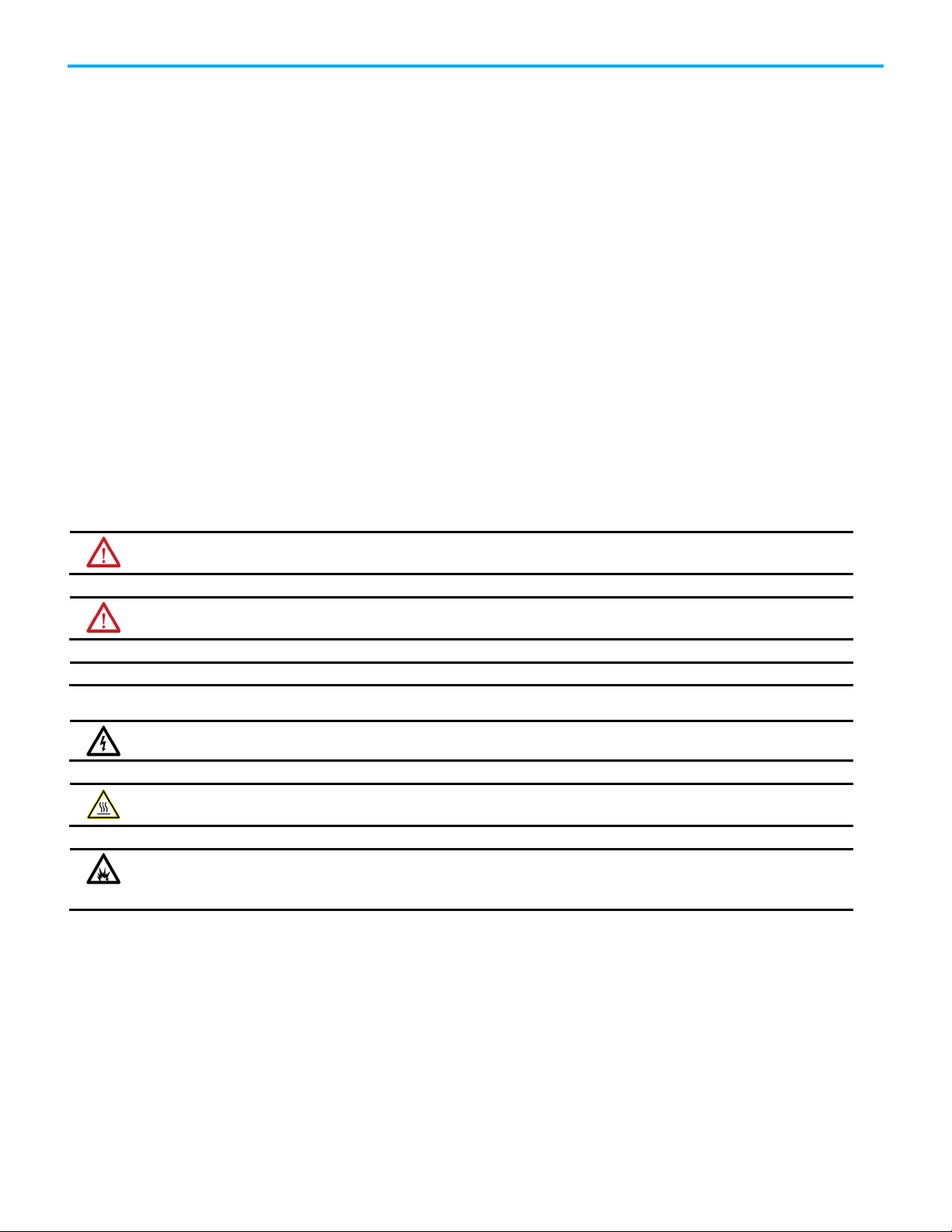
Analog Alarm (ALMA)
This information applies to the CompactLogix 5370, ControlLogix 5570,
Compact GuardLogix 5370, GuardLogix 5570, Compact GuardLogix 5380,
CompactLogix 5380, CompactLogix 5480, ControlLogix 5580, and GuardLogix
5580 controllers. Controller differences are noted where applicable.
The ALMA instruction provides level and rate-of-change alarming for any
analog signal.
Ladder Diagram
22 Publication 1756-RM003V-EN-P - November 2020
Page 23
Operand
Type
Format
Description
ALMA
ALARM_ANALOG
Structure
ALMA structure
SINT
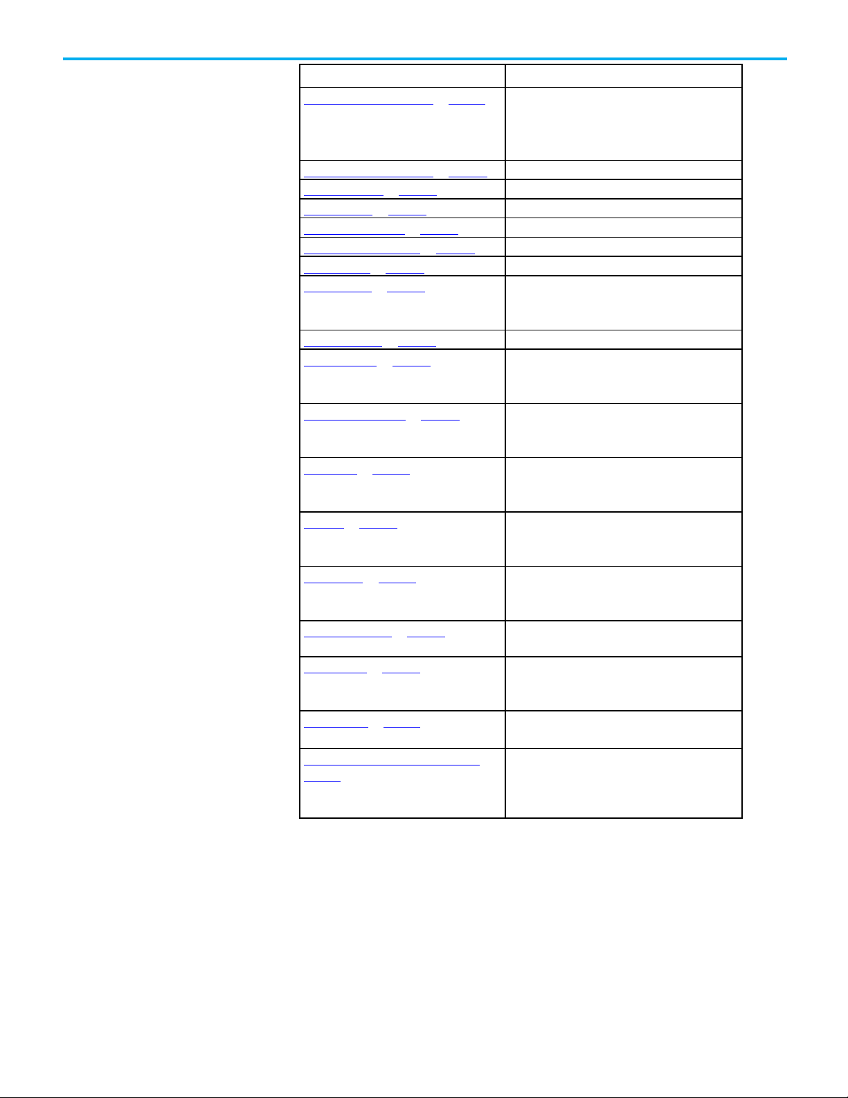
Function Block
Chapter 1 Alarm Instructions
Structured Text
ALMA (ALMA,In,ProgAckAll,ProgDisable,ProgEnable)
Operands
Ladder Diagram
In REAL
DINT
INT
ProgAckAll BOOL Tag
ProgDisable BOOL Tag
ProgEnable BOOL Tag
Tag
Immediate
Immediate
Immediate
Immediate
The alarm input value, which is
compared with alarm limits to
detect the alarm condition.
On transition from False to True,
acknowledges all alarm
conditions that require
acknowledgement.
When True, disables alarm (does
not override Enable Commands).
When True, enables alarm (takes
precedence over Disable
commands).
Publication 1756-RM003V-EN-P - November 2020 23
Page 24

Chapter 1 Alarm Instructions
Operand
Type
Format
Description
Operand
Type
Format
Description
SINT
require acknowledgement.
Immediate
override Enable Commands).
Input Parameter
Data Type
Description
Default is set.
Copied from instruction operand.
Function Block
ALMA tag ALARM_ANALOG structure ALMA structure
Structured Text
ALMA ALARM_ANALOG Structure ALMA structure
In REAL
DINT
INT
Tag
Immediate
The alarm input value, which is
compared with alarm limits to detect
the alarm condition.
ProgAckAll BOOL Tag
Immediate
ProgDisable BOOL Tag
ProgEnable BOOL Tag
Immediate
On transition from False to True,
acknowledges all alarm conditions that
When True, disables alarm (does not
When True, enables alarm (takes
precedence over Disable commands).
See Structured Text Syntax for more information on the syntax of expressions
within the structured text.
ALMA Structure
Input Parameters
EnableIn BOOL Ladder Diagram:
Corresponds to the rung state. If false, the instruction does not execute
and outputs are not updated.
Structured Text:
If false, the instruction does not execute and outputs are not updated.
Default is set.
Function Block:
If false, the instruction does not execute and outputs are not updated.
24 Publication 1756-RM003V-EN-P - November 2020
In REAL The alarm input value, which is compared with alarm limits to detect the
alarm condition.
Default = 0.0.
Ladder Diagram:
Copied from instruction operand.
Structured Text:
Page 25

Input Parameter
Data Type
Description
Default is false (good health).
Default is set.
Default is set.
Default is set.
Copied from the instruction operand.
Default is false.
Default is false.
Chapter 1 Alarm Instructions
InFault BOOL Bad health indicator for the input. The user application may set InFault to
indicate the input signal has an error. When set, the instruction sets
InFaulted (Status.1). When cleared to false, the instruction clears InFaulted
to false (Status.1). In either case, the instruction continues to evaluate In
for alarm conditions.
HHEnabled BOOL High High alarm condition detection. Set to true to enable detection of the
High High alarm condition. Clear to false to make detection unavailable for
the High High alarm condition.
Default is set.
HEnabled BOOL High alarm condition detection. Set to true to enable detection of the High
alarm condition. Clear to false to make detection unavailable for the High
alarm condition.
LEnabled BOOL Low alarm condition detection. Set to true to enable detection of the Low
alarm condition. Clear to false to make detection unavailable for the Low
alarm condition.
LLEnabled BOOL Low Low alarm condition detection. Set to true to enable detection of the
Low Low alarm condition. Clear to false to make detection unavailable for
the Low Low alarm condition.
AckRequired BOOL Specifies whether alarm acknowledgment is required. When set to true,
acknowledgment is required. When cleared to false, acknowledgment is
not required and HHAcked, HAcked, LAcked, LLAcked, ROCPosAcked, and
ROCNegAcked are always set to true
Default is true.
ProgAckAll BOOL Set to true by the user program to acknowledge all alarm conditions.
Takes effect only if any alarm condition is unacknowledged. Requires a
false-to-true transition.
Default is false.
Ladder Diagram:
Copied from the instruction operand.
Structured Text:
OperAckAll BOOL Set to true by the operator interface to acknowledge all alarm conditions.
Takes effect only if any alarm condition is unacknowledged. The alarm
instruction clears this parameter to false.
HHProgAck BOOL High High program acknowledge. Set to true by the user program to
acknowledge a High High condition. Takes effect only if the alarm
condition is unacknowledged. Requires a false -to-true transition.
Default is false.
HHOperAck BOOL High High operator acknowledge. Set to true by the operator interface to
acknowledge a High High condition. Takes effect only if the alarm
condition is unacknowledged. The alarm instruction clears this parameter
to false.
Publication 1756-RM003V-EN-P - November 2020 25
Page 26

Chapter 1 Alarm Instructions
Input Parameter
Data Type
Description
Default is false.
Default is false.
Default is false.
Default is false.
Default is false.
Default is false.
Default is false.
Default is cleared.
Default is false.
HProgAck BOOL High program acknowledge. Set to true by the user program to
acknowledge a High condition. Takes effect only if the alarm condition is
unacknowledged. Requires a false-to-true transition.
HOperAck BOOL High operator acknowledge. Set to true by the operator interface to
acknowledge a High condition. Takes effect only if the alarm condition is
unacknowledged. The alarm instruction clears this parameter to false.
LProgAck BOOL Low program acknowledge. Set to true by the user program to
acknowledge a Low condition. Takes effect only if the alarm condition is
unacknowledged. Requires a false-to-true transition.
Default is false.
LOperAck BOOL Low operator acknowledge. Set to true by the operator interface to
acknowledge a Low condition. Takes effect only if the alarm condition is
unacknowledged. The alarm instruction clears this parameter to false.
LLProgAck BOOL Low Low program acknowledge. Set to true by the user program to
acknowledge a Low Low condition. Takes effect only if the alarm
condition is unacknowledged. Requires a false-to-true transition.
LLOperAck BOOL Low Low operator acknowledge. Set to true by the operator interface to
acknowledge a Low Low condition. Takes effect only if the alarm
condition is unacknowledged. The alarm instruction clears this parameter
false.
Default is false.
ROCPosProgAck BOOL Positive rate of change program acknowledge. Set to true by the user
program to acknowledge a positive rate-of-change condition. Requires a
false-to-true transition while the alarm condition is unacknowledged.
ROCPosOperAck BOOL Positive rate of change operator acknowledge. Set to true by the operator
interface to acknowledge a positive rate-of-change condition. Requires a
false-to-true transition while the alarm condition is unacknowledged. The
alarm instruction sets this parameter to false.
ROCNegProgAck BOOL Negative rate of change program acknowledge. Set to true by the user
program to acknowledge a negative rate-of-change condition. Requires a
false-to-true transition while the alarm condition is unacknowledged.
Default is false.
ROCNegOperAck BOOL Negative rate of change operator acknowledge. Set to true by the operator
interface to acknowledge a negative rate-of-change condition. Requires a
false-to-true transition while the alarm condition is unacknowledged. The
alarm instruction clears this parameter to false.
ProgSuppress BOOL Set to true by the user program to suppress the alarm.
OperSuppress BOOL Set to true by the operator interface to suppress the alarm. The alarm
instruction clears this parameter to false.
ProgUnsuppress BOOL Set to true by the user program to unsuppress the alarm. Takes
precedence over Suppress commands.
Default is false.
26 Publication 1756-RM003V-EN-P - November 2020
Page 27

Input Parameter
Data Type
Description
Default is false.
again. It becomes unacknowledged when the shelve duration ends.
Unshelve commands take precedence over Shelve commands.
Unshelve commands take precedence over Shelve commands.
Unshelve commands take precedence over Shelve commands.
Default is false.
Chapter 1 Alarm Instructions
OperUnsuppress BOOL Set to true by the operator interface to unsuppress the alarm. Takes
precedence over Suppress commands. The alarm instruction sets this
parameter to false.
HHOperShelve BOOL High-high operator shelve. Set to true by the operator interface to shelve
or reshelve a high-high condition. Requires a false-to-true transition. The
alarm instruction clears this parameter to false.
Default is false.
Unshelve commands take precedence over Shelve commands.
Shelving an alarm postpones alarm processing. It is like suppressing an
alarm, except that shelving is time limited. If an alarm is acknowledged
while it is shelved, it remains acknowledged even if it becomes active
HOperShelve BOOL High operator shelve. Set to true by the operator interface to shelve or
reshelve a high condition. Requires a transition from false in one program
scan to true in the next program scan. The alarm instruction clears this
parameter to false.
Default is false.
Unshelve commands take precedence over Shelve commands.
LOperShelve BOOL Low operator shelve. Set to true by the operator interface to shelve or
reshelve a low condition. Requires a transition false in one program scan
to true in the next program scan. The alarm instruction clears this
parameter to false.
Default is false.
LLOperShelve BOOL Low-low operator shelve. Set to true by the operator interface to shelve or
reshelve a low-low condition. Requires a transition from false in one
program scan to true in the next program scan. The alarm instruction
clears this parameter to false.
Default is false.
Unshelve commands take precedence over Shelve commands.
ROCPosOperShelve BOOL Positive rate-of-change operator shelve. Set to true by the operator
interface to shelve or reshelve a positive rate-of-change condition.
Requires a transition from false in one program scan to true in the next
program scan. The alarm instruction clears this parameter to false.
Default is false.
ROCNegOperShelve BOOL Negative rate-of-change operator shelve. Set to true by the operator
interface to shelve or reshelve a negative rate-of-change condition.
Requires a transition from false in one program scan to true in the next
program scan. The alarm instruction clears this parameter to false.
Default is false.
ProgUnshelveAll BOOL Set to true by the user program to unshelve all conditions on this alarm. If
both shelve and unshelve are true, unshelve commands take precedence
over shelve commands.
HHOperUnshelve BOOL High-high operator unshelve. Set to true by the operator interface to
unshelve a high-high condition. The alarm instruction clears this
parameter to false. If both shelve and unshelve are true, unshelve
commands take precedence over shelve commands.
Default is false.
Publication 1756-RM003V-EN-P - November 2020 27
Page 28

Chapter 1 Alarm Instructions
Input Parameter
Data Type
Description
Default is false.
Default is false.
Default is false.
Default is false.
Default is false.
ProgEnable
BOOL
Copied from the instruction operand.
Default is false.
Default is false.
Default is true.
HOperUnshelve BOOL High operator unshelve. Set to true by the operator interface to unshelve a
high condition. The alarm instruction clears this parameter to false. If
both shelve and unshelve are true, unshelve commands take precedence
over shelve commands.
LOperUnshelve BOOL Low operator unshelve. Set to true by the operator interface to unshelve a
low condition. The alarm instruction clears this parameter to false. If both
shelve and unshelve are true, unshelve commands take precedence over
shelve commands.
Default is false.
LLOperUnshelve BOOL Low-low operator unshelve. Set to true by the operator interface to
unshelve a low-low condition. The alarm instruction clears this parameter
to false. If both shelve and unshelve are true, unshelve commands take
precedence over shelve commands.
ROCPosOperUnshelve BOOL Positive rate-of-change operator unshelve. Set to true by the operator
interface to unshelve a positive rate-of-change condition. The alarm
instruction clears this parameter to false. If both shelve and unshelve are
set, unshelve commands take precedence over shelve commands.
ROCNegOperUnshelve BOOL Negative rate-of-change operator unshelve. Set to true by the operator
interface to unshelve a negative rate-of-change condition. The alarm
instruction clears this parameter to false. If both shelve and unshelve are
true, unshelve commands take precedence over shelve commands.
ProgDisable BOOL Copied from the instruction operand.
OperDisable BOOL Set to true by the operator interface to disable the alarm. The alarm
instruction clears this parameter to false.
OperEnable BOOL Set to true by the operator interface to enable the alarm. Takes
precedence over Disable command. The alarm instruction clears this
parameter false.
AlarmCountReset BOOL Set to true by the operator interface to reset the alarm counts for all
conditions. The alarm instruction clears this parameter to false.
HHMinDurationEnable BOOL High-high minimum duration enable. Set to true to enable minimum
duration timer when detecting the high-high condition.
Default is true.
HMinDurationEnable BOOL High minimum duration enable. Set to true to enable minimum duration
timer when detecting the high condition.
Default is true.
LMinDurationEnable BOOL Low minimum duration enable. Set to true to enable minimum duration
timer when detecting the low condition.
28 Publication 1756-RM003V-EN-P - November 2020
LLMinDurationEnable BOOL Low-low minimum duration enable. Set to true to enable minimum
duration timer when detecting the low-low condition.
Default is true.
Page 29

Input Parameter
Data Type
Description
Default = 500.
Default = 0.0.
Default = 500.
Default = 0.0.
Default = 500.
Default = 500.
Chapter 1 Alarm Instructions
HHLimit REAL High High alarm limit.
Valid = HLimit < HHLimit < maximum positive float.
Default = 0.0.
HHSeverity DINT Severity of the High High alarm condition. This does not affect processing
of alarms by the controller, but can be used for sorting and filtering
functions at the alarm subscriber.
Valid = 1...1000 (1000 = most severe; 1 = least severe).
HLimit REAL High alarm limit.
Valid = LLimit < HLimit < HHLimit.
HSeverity DINT Severity of the High alarm condition. This does not affect processing of
alarms by the controller, but can be used for sorting and filtering
functions at the alarm subscriber.
Valid = 1...1000 (1000 = most severe; 1 = least severe).
LLimit REAL Low alarm limit.
Valid = LLLimit < LLimit < HLimit.
LSeverity DINT Severity of the Low alarm condition. This does not affect processing of
alarms by the controller, but can be used for sorting and filtering
functions at the alarm subscriber.
Valid = 1...1000 (1000 = most severe; 1 = least severe).
LLLimit REAL Low Low alarm limit.
Valid = maximum negative float < LLLimit < LLimit.
Default = 0.0.
LLSeverity DINT Severity of the Low Low alarm condition. This does not affect processing
of alarms by the controller, but can be used for sorting and filtering
functions at the alarm subscriber.
Valid = 1...1000 (1000 = most severe; 1 = least severe).
MinDurationPRE DINT Minimum duration preset (milliseconds) for an alarm level condition to
remain true before the condition is marked as InAlarm and alarm
notification is sent to clients. The controller collects alarm data as soon
as the alarm condition is detected; so no data is lost while waiting to meet
the minimum duration. Does not apply to rate-of-change conditions or to
conditions for which minimum duration detection is disabled.
MinDurationPRE only applies to the first excursion from normal in either
direction. For example, once the High condition times out, the High High
condition becomes active immediately, while a Low condition waits for
the timeout period.
Valid = 0...2147483647.
Default = 0.
ShelveDuration DINT Time duration (in minutes) for which a shelved alarm will be shelved.
Minimum time is one minute. Maximum time is defined by
MaxShelveDuration.
MaxShelveDuration DINT Maximum time duration (in minutes) for which an alarm can be shelved.
Publication 1756-RM003V-EN-P - November 2020 29
Page 30

Chapter 1 Alarm Instructions
Input Parameter
Data Type
Description
Default = 0.0.
Default = 0.0.
Default = 500.
Default = 0.0.
Deadband REAL Deadband for detecting that High High, High, Low, and Low Low alarm
levels have returned to normal.
A non-zero Deadband can reduce alarm condition chattering if the In
value is continually changing but remaining near the level condition
threshold. The Deadband value does not affect the transition to the
InAlarm (active) state. Once a level condition is active, but before the
condition returns to the inactive (normal) state, the In value must either:
drop below the threshold minus the deadband (for High and High High
conditions).
OR
rise above the threshold plus the deadband (for Low and Low Low
conditions).
The Deadband is not used to condition the Minimum Duration time
measurement.
Valid = 0 = Deadband < Span from first enabled Low alarm to the first
enabled High alarm.
Default = 0.0.
ROCPosLimit REAL Limit for an increasing rate-of-change in units per second. Detection is
enabled for any value > 0.0 if ROCPeriod is also > 0.0.
Valid = 0.0...maximum possible float.
ROCPosSeverity DINT Severity of the increasing rate-of-change condition. This does not affect
processing of alarms by the controller, but can be used for sorting and
filtering functions at the alarm subscriber.
Valid = 1...1000 (1000 = most severe; 1 = least severe).
Default = 500.
ROCNegLimit REAL Limit for a decreasing rate-of-change in units per second. Detection is
enabled for any value > 0.0 if ROCPeriod is also > 0.0.
Valid = 0.0...maximum possible float.
ROCNegSeverity DINT Severity of the decreasing rate-of-change condition. This does not affect
processing of alarms by the controller, but can be used for sorting and
filtering functions at the alarm subscriber.
Valid = 1...1000 (1000 = most severe; 1 = least severe).
ROCPeriod REAL Time period in seconds for calculation (sampling interval) of the rate of
change value. Each time the sampling interval expires, a new sample of In
is stored, and ROC is re-calculated. Instead of an enable bit like other
conditions in the analog alarm, the rate-of-change detection is enabled by
putting any non-zero value in the ROCPeriod.
Valid = 0.0...32767.0
Output Parameters
These output parameters are common to ladder logic.
30 Publication 1756-RM003V-EN-P - November 2020
Page 31

Output Parameter
Data Type
Description
Cleared to false when no Low condition exists.
Active. Cleared to false when no Low Low condition exists.
positive rate-of-change condition exists.
negative rate-of-change condition exists.
acknowledged.
Cleared to false when a High condition is not acknowledged.
rate-of-change condition is not acknowledged.
negative rate-of-change condition is not acknowledged.
acknowledged, or both.
Chapter 1 Alarm Instructions
AnyInAlarmUnack BOOL Combined alarm active and acknowledged status. Set to true when any
alarm condition is detected and unacknowledged. Cleared to false when
all alarm conditions are inactive, acknowledged, or both.
HHInAlarm BOOL High High alarm condition status. Set to true when a High High condition
is Active. Cleared to false when no High High condition exists.
HInAlarm BOOL High alarm condition status. Set to true when a High condition is Active.
Cleared to false when no High condition exists.
LInAlarm BOOL Low alarm condition status. Set to true when a Low condition is Active.
LLInAlarm BOOL Low Low alarm condition status. Set to true when a Low Low condition is
ROCPosInAlarm BOOL Positive rate-of-change alarm condition status. Set to true when a
positive rate-of-change condition exists. Cleared to false when no
ROCNegInAlarm BOOL Negative rate-of-change alarm condition status. Set to true when a
negative rate-of-change condition exists. Cleared to False when no
ROC REAL Calculated rate-of-change of the In value. This value is updated when
the instruction is scanned following each elapsed ROCPeriod. The ROC
value is used to evaluate the ROCPosInAlarm and ROCNegInAlarm
conditions.
ROC = (current sample of In – previous sample of In) / ROCPeriod
HHAcked BOOL High High condition acknowledged status. Set to true when a High High
condition is acknowledged. Always set to true when AckRequired is
cleared to false. Cleared to false when a High High condition is not
HAcked BOOL High condition acknowledged status. Set to true when a High condition is
acknowledged. Always set to true when AckRequired is cleared to false.
LAcked BOOL Low condition acknowledged status. Set to true when a Low condition is
acknowledged. Always set to true when AckRequired is cleared to false.
Cleared to false when a Low condition is not acknowledged.
LLAcked BOOL Low Low condition acknowledged status. Set to true when a Low Low
condition is acknowledged. Always true when AckRequired is cleared to
false. Cleared to false when a Low Low condition is not acknowledged.
ROCPosAcked BOOL Positive rate-of-change condition acknowledged status. Set to true
when a positive rate-of-change condition is acknowledged. Always true
when AckRequired is cleared to false. Cleared to false when a positive
ROCNegAcked BOOL Negative rate-of-change condition acknowledged status. Set to true
when a negative rate-of-change condition is acknowledged. Always set
to true when AckRequired is cleared to false. Cleared to false when a
HHInAlarmUnack BOOL Combined High High condition active and unacknowledged status. Set to
true when the High High condition is active (HHInAlarm is true) and
unacknowledged. Cleared to false when the High High condition is
inactive, acknowledged, or both.
HInAlarmUnack BOOL Combined High condition active and unacknowledged status. Set to true
when the High condition is active (HInAlarm is true) and
unacknowledged. Cleared to false when the High condition is inactive,
Publication 1756-RM003V-EN-P - November 2020 31
Page 32

Chapter 1 Alarm Instructions
Output Parameter
Data Type
Description
both.
inactive, acknowledged, or both.
positive rate-of-change condition is inactive, acknowledged, or both.
acknowledged, or both.
suppressed. Cleared to false when the alarm is not suppressed.
unshelved.
shelved. Cleared to false when high condition is unshelved.
shelved. Cleared to false when low condition is unshelved.
is shelved. Cleared to false when low-low condition is unshelved.
positive rate-of-change condition is unshelved.
MinDurationACC
DINT
Not Used. Value is always 0.
active state.
maximum count value.
active state.
LInAlarmUnack BOOL Combined Low condition active and unacknowledged status. Set to true
when the Low condition is active (LInAlarm is true) and unacknowledged.
Cleared to false when the Low condition is inactive, acknowledged, or
LLInAlarmUnack BOOL Combined Low Low condition active and unacknowledged status. Set to
true when the Low Low condition is active (LLInAlarm is true) and
unacknowledged. Cleared to false when the Low Low condition is
ROCPosInAlarmUnack BOOL Combined positive rate-of-change condition active and unacknowledged
status. Set to true when the positive rate-of-change condition is active
(ROCPosInAlarm is true) and unacknowledged. Cleared to false when the
ROCNegInAlarmUnack BOOL Combined negative rate-of-change condition active and
unacknowledged status. Set to true when the negative rate-of-change
condition is active (ROCNegInAlarm is true) and unacknowledged.
Cleared to false when the negative rate-of-change condition is inactive,
Suppressed BOOL Suppressed status of the alarm. Set to true when the alarm is
HHShelved BOOL High-high condition shelved status. Set to true when a high-high
condition is shelved. Cleared to false when high-high condition is
HShelved BOOL High condition shelved status. Set to true when a high condition is
LShelved BOOL Low condition shelved status. Set to true when a low condition is
LLShelved BOOL Low-low condition shelved status. Set to true when a low-low condition
ROCPosShelved BOOL Positive rate-of-change condition shelved status. Set to true when a
positive rate-of-change condition is shelved. Cleared to false when
ROCNegShelved BOOL Negative rate-of-change condition shelved status. Set to true when a
negative rate-of-change condition is shelved. Cleared to false when
negative rate-of-change condition is unshelved.
Disabled BOOL Disabled status of the alarm. Set to true when the alarm is unavailable
(disabled). Cleared to false when the alarm is enabled.
Commissioned BOOL The commissioned bit is not used.
HHInAlarmTime LINT Timestamp when the ALMA instruction detected that the In value
exceeded the High High condition limit for the most recent transition to
the active state.
HHAlarmCount DINT The number of times the High High condition has been activated. If the
maximum value is reached, the counter leaves the value at the
maximum count value.
HInAlarmTime LINT Timestamp when the ALMA instruction detected that the In value
exceeded the High condition limit for the most recent transition to the
HAlarmCount DINT The number of times the High condition has been activated. If the
LInAlarmTime LINT Timestamp when the ALMA instruction detected that the In value
32 Publication 1756-RM003V-EN-P - November 2020
maximum value is reached, the counter leaves the value at the
exceeded the Low condition limit for the most recent transition to the
Page 33

Output Parameter
Data Type
Description
the active state.
maximum count value.
transition to the active state.
at the maximum count value.
condition alarm time.
RetToNormalTime
LINT
Timestamp of alarm returning to a normal state.
shelved the timestamp is set to current time.
Chapter 1 Alarm Instructions
LAlarmCount DINT The number of times the Low condition has been activated. If the
maximum value is reached, the counter leaves the value at the
maximum count value.
LLInAlarmTime LINT Timestamp when the ALMA instruction detected that the In value
exceeded the Low Low condition limit for the most recent transition to
LLAlarmCount DINT The number of times the Low Low condition has been activated. If the
maximum value is reached, the counter leaves the value at the
ROCPosInAlarmTime LINT Timestamp when the ALMA instruction detected that the In value
exceeded the positive-rate-of-change condition limit for the most recent
ROCPosInAlarmCount DINT The number of times the positive rate-of-change condition has been
activated. If the maximum value is reached, the counter leaves the value
ROCNegInAlarmTime LINT Timestamp when the ALMA instruction detected that the In value
exceeded the negative-rate-of-change condition limit for the most
recent transition to the active state.
ROCNegAlarmCount DINT The number of times the negative rate-of-change condition has been
activated. If the maximum value is reached, the counter leaves the value
at the maximum count value.
AckTime LINT Timestamp of most recent condition acknowledgment. If the alarm does
not require acknowledgment, this timestamp is equal to most recent
AlarmCountResetTime LINT Timestamp indicating when the alarm count was reset.
ShelveTime LINT Timestamp indicates when an alarm condition was shelved the last time.
Set by controller when alarm condition is shelved. Alarm conditions can
be shelved and unshelved many times. Each time alarm condition is
UnshelveTime LINT Timestamp indicating when all alarm conditions are going to be
unshelved. Value is set only when no alarm condition is shelved yet. The
timestamp is determined as sum of the ShelveDuration time period and
current time. If an alarm condition is unshelved programmatically or by
an operator and no other alarm condition is shelved, then value is set to
the current time.
Publication 1756-RM003V-EN-P - November 2020 33
Page 34

Chapter 1 Alarm Instructions
Output Parameter
Data Type
Description
InstructFault
Status.1 = InFaulted
X
X
Status.2 = SeverityInv
X
X
AlarmLimitsInv
ROCPosLimitInv
ROCNegLimitInv
If severity >1000, the instruction uses Severity = 1000.
fault is cleared, no new level conditions can be detected.
enabled high alarm.
= 0.0, which makes rate-of-change detection unavailable.
Compact GuardLogix 5380, and GuardLogix 5580 controllers only.
Status DINT Combined status indicators:
Status Flag CompactLogix 5370,
ControlLogix 5570,
Compact GuardLogix
5370, GuardLogix
5570 controllers
Status.0 =
CompactLogix
5380,
CompactLogix
5480, ControlLogix
5580, Compact
GuardLogix 5380,
and GuardLogix
5580 controllers
X X
Status.3 =
Status.4 =
X X
X X
DeadbandInv
Status.5 =
Status.6 =
Status.7 =
X X
X X
X X
ROCPeriodInv
Status.8 = Overflow - X
InstructFault (Status.0) BOOL Instruction error conditions exist. This is not a minor or major controller
error. Check the remaining status bits to determine what occurred.
InFaulted (Status.1) BOOL User program has set InFault to indicate bad quality input data. Alarm
continues to evaluate In for alarm conditions.
SeverityInv (Status.2) BOOL Alarm severity configuration is invalid.
If severity <1, the instruction uses Severity = 1.
AlarmLimitsInv (Status.3) BOOL Alarm Limit configuration is invalid (for example, LLimit < LLLimit). If
invalid, the instruction clears all level conditions active bits. Until the
DeadbandInv (Status.4) BOOL Deadband configuration is invalid. If invalid, the instruction uses
Deadband = 0.0.
Valid = 0 = Deadband < Span from first enabled low alarm to the first
34 Publication 1756-RM003V-EN-P - November 2020
ROCPosLimitInv (Status.5) BOOL Positive rate-of-change limit invalid. If invalid, the instruction uses
ROCPosLimit = 0.0, which makes positive rate-of-change detection
unavailable.
ROCNegLimitInv (Status.6) BOOL Negative rate-of-change limit invalid. If invalid, the instruction uses
ROCNegLimit = 0.0, which makes negative rate-of-change detection
unavailable.
ROCPeriodInv (Status.7) BOOL Rate-of-change period invalid. If invalid, the instruction uses ROCPeriod
Overflow
(Status.8)
BOOL The Overflow bit is set to true when an overflow condition is detected.
The overflow bit is cleared to false when the overflow condition has been
corrected.
Applies to CompactLogix 5380, CompactLogix 5480, ControlLogix 5580,
Page 35

Controllers
Affected Math Status Flags
controllers
GuardLogix 5370, GuardLogix 5570 controllers
A minor fault will occur if:
Fault Type
Fault Code
Chapter 1 Alarm Instructions
Connect a button to the OperShelve tag
The alarm instruction only processes the OperShelve tag on transition from
cleared to set to prevent unwanted reshelving of the alarm. For example, if an
operator presses a push button to shelve the alarm while the ProgUnshelve tag
is set, the alarm is not shelved because the ProgUnshelve tag takes
precedence. To shelve the alarm, the operator can release and press the push
button again once ProgUnshelve is cleared.
Affects Math Status Flags
CompactLogix 5380, CompactLogix 5480, ControlLogix
5580, Compact GuardLogix 5380, and GuardLogix 5580
CompactLogix 5370, ControlLogix 5570, Compact
Conditional
Yes
The input value is INF or NAN for CompactLogix 5370,
ControlLogix 5570, Compact GuardLogix 5370,
GuardLogix 5570 controllers only.
See Math Status Flags.
4 4
Major/Minor Faults
None specific to this instruction. See Index Through Arrays for arrayindexing faults.
Publication 1756-RM003V-EN-P - November 2020 35
Analog Alarm State Diagrams
These illustrations show the manner in which an analog alarm responds to
changing alarm conditions and operator commands.
Page 36

Chapter 1 Alarm Instructions
36 Publication 1756-RM003V-EN-P - November 2020
Page 37

Chapter 1 Alarm Instructions
Publication 1756-RM003V-EN-P - November 2020 37
Page 38

Chapter 1 Alarm Instructions
38 Publication 1756-RM003V-EN-P - November 2020
Page 39

Chapter 1 Alarm Instructions
Analog Alarm Timing Diagrams
These timing diagrams show the sequence of analog alarm operations.
Publication 1756-RM003V-EN-P - November 2020 39
Page 40

Chapter 1 Alarm Instructions
Level Conditions Behavior Acknowledge
40 Publication 1756-RM003V-EN-P - November 2020
Page 41

Level Conditions Behavior No Acknowledge
Chapter 1 Alarm Instructions
Publication 1756-RM003V-EN-P - November 2020 41
Page 42

Chapter 1 Alarm Instructions
ROC Conditions Behavior Acknowledge
42 Publication 1756-RM003V-EN-P - November 2020
Page 43

Condition/State
Action Taken
Rung-condition-in is false
Rung-condition-out is cleared to false.
The instruction executes
ROC Conditions Behavior No Acknowledge
Chapter 1 Alarm Instructions
Execution
Ladder Diagram
Prescan Rung-condition-out is cleared to false.
All of the ALMA structure parameters are cleared
All alarm conditions are acknowledged.
All operator requests are cleared
All timestamps are cleared
All delivery flags are cleared.
Rung-condition-in is true Rung-condition-out is set to true
Postscan Rung-condition-out is cleared to false
Publication 1756-RM003V-EN-P - November 2020 43
Page 44

Chapter 1 Alarm Instructions
Condition/State
Action Taken
Postscan
Tag.EnableOut is cleared to false
Condition/State
Action Taken
Function Block
Prescan Tag.EnableOut is cleared to false.
All of the ALMA structure parameters are cleared
All alarm conditions are acknowledged.
All operator requests are cleared
All timestamps are cleared
All delivery flags are cleared.
Tag.EnableIn is false Tag.EnableOut is cleared to false
Tag.EnableIn is true The instruction executes
Tag.EnableOut is set to true
Instruction first run N/A
Instruction first scan N/A
Structured Text
In Structured Text, EnableIn is always true during normal scan. Therefore, if
the instruction is in the control path activated by the logic it will execute.
Prescan See Prescan in the Ladder Diagram table.
Normal Execution See Rung-condition-in is true in the Ladder
Diagram table.
Postscan See Postscan in the Ladder Diagram table.
Examples
Ladder Diagram
44 Publication 1756-RM003V-EN-P - November 2020
Page 45

Chapter 1 Alarm Instructions
Function Block
An example of an ALMA instruction in Function Block is shown below. In this
example, the Tank 32 Level Transmitter (Tank32LT) is monitored for alarm
conditions. The Tank32LevelAck tag can be used to acknowledge all conditions
of this alarm.
Structured Text
In this example, the Tank 32 Level Transmitter (Tank32LT) is monitored for
alarm conditions. The Tank32LevelAck tag can be used to acknowledge all
conditions of this alarm.
ALMA(Tank32Level,Tank32LT,Tank32LevelAck,0, 0);
See also
Structured Text Syntax on page 915
Math Status Flags on page 887
Index Through Arrays on page 898
Publication 1756-RM003V-EN-P - November 2020 45
Page 46

Chapter 1 Alarm Instructions
Digital Alarm (ALMD)
This information applies to the CompactLogix 5370, ControlLogix 5570,
Compact GuardLogix 5370, GuardLogix 5570, Compact GuardLogix 5380,
CompactLogix 5380, CompactLogix 5480, ControlLogix 5580, and GuardLogix
5580 controllers.
The ALMD instruction provides alarming for any discrete Boolean value.
Available Languages
Ladder Diagram
Function Block
Structured Text
ALMD (ALMD,In,ProgAck,ProgReset,ProgDisable,ProgEnable)
46 Publication 1756-RM003V-EN-P - November 2020
Page 47

Operand
Type
Format
Description
Immediate
acknowledgment is required).
Immediate
Immediate
Immediate
reported (milliseconds).
timer.
Operand
Type
Format
Description
Operand
Type
Format
Description
Immediate
acknowledgment is required).
Immediate
Operands
Ladder Diagram
ALMD tag ALARM_DIGITAL Structure ALMD structure
ProgAck BOOL Tag
On transition from false to true, acknowledges alarm (if
Chapter 1 Alarm Instructions
ProgReset BOOL Tag
ProgDisable BOOL Tag
ProgEnable BOOL Tag
MinDurationPRE DINT Immediate Specifies how long the alarm condition must be met before it is
MinDurationACC DINT Immediate Indicates the current accumulator value for the alarm’s MinDuration
On transition from false to true, resets alarm (if resetting is required).
When True, disables alarm (does not override Enable Commands).
When True, enables alarm (takes precedence over Disable commands).
Function Block
ALMD tag ALARM_DIGITAL structure ALMD structure
Structured Text
ALMD tag ALARM_DIGITAL Structure ALMD structure
ProgAck BOOL Tag
On transition from false to true, acknowledges alarm (if
Publication 1756-RM003V-EN-P - November 2020 47
ProgReset BOOL Tag
ProgDisable BOOL Tag
Immediate
ProgEnable BOOL Tag
Immediate
MinDurationPRE DINT Immediate Specifies how long the alarm condition must be met before it is
MinDurationACC DINT Immediate Indicates the current accumulator value for the alarm’s MinDuration
On transition from false to true, resets alarm (if resetting is required).
When True, disables alarm (does not override Enable Commands).
When True, enables alarm (takes precedence over Disable commands).
reported (milliseconds).
timer.
See Structured Text Syntax for more information on the syntax of expressions
within structured text.
Page 48

Chapter 1 Alarm Instructions
Input Parameter
Data Type
Description
No effect. The instruction always executes.
Default is false (good health).
Default is true.
A latched alarm can only be reset when the alarm condition is false.
Copied from the instruction operand.
Default is false.
EnableIn BOOL Ladder Diagram:
In BOOL The digital signal input to the instruction.
InFault BOOL Bad health indicator for the input. The user application may set InFault to indicate the input
ALMD Structure
Input Parameters
Corresponds to the rung state. Does not affect processing.
Function Block:
If cleared to false, the instruction does not execute and outputs are not updated.
If set, the instruction executes.
Default is true.
Structured Text:
Default is false.
Ladder Diagram:
Follows the rung condition. Set to true if the rung condition is true. Cleared to false if the rung
condition is false.
Structured Text:
Copied from instruction operand.
signal has an error. When set, the instruction sets InFaulted (Status.1). When cleared to false,
the instruction clears the InFaulted (Status.1) to false. In either case, the instruction continues
to evaluate In for alarm conditions.
Condition BOOL Specifies how alarm is activated. When Condition is set to true, the alarm condition is
activated when In is set to true. When Condition is cleared to false, the alarm condition is
activated when In is Cleared to false.
AckRequired BOOL Specifies whether alarm acknowledgment is required. When set to true, acknowledgment is
required. When cleared to false, acknowledgment is not required and Acked is always set to
true.
Default is true.
Latched BOOL Specifies whether the alarm is latched. Latched alarms remain InAlarm when the alarm
condition becomes false, until a Reset command is received. When set to true, the alarm is
latched. When cleared to false, the alarm is unlatched.
Default is false.
ProgAck BOOL Set to true by the user program to acknowledge the alarm. Takes effect only if the alarm is
unacknowledged. Requires a false-to-true transition.
Default is false.
Ladder Diagram:
Copied from the instruction operand.
Structured Text:
OperAck BOOL Set to true by the operator interface to acknowledge the alarm. Takes effect only if the alarm
is unacknowledged. The instruction clears this parameter.
48 Publication 1756-RM003V-EN-P - November 2020
Page 49

Input Parameter
Data Type
Description
Copied from the instruction operand.
Default is false.
Default is false.
Default is false.
duration ends provided the alarm is still active at that moment.
For more information on shelving an alarm, see the description for the OperShelve parameter.
For more information on shelving an alarm, see the description for the OperShelve parameter.
Copied from the instruction operand.
Chapter 1 Alarm Instructions
ProgReset BOOL Set to true by the user program to reset the latched alarm. Takes effect only if the latched
alarm is InAlarm and the alarm condition is false. Requires a false-to-true transition.
Default is false.
Ladder Diagram:
Copied from the instruction operand.
Structured Text:
OperReset BOOL Set to true by the operator interface to reset the latched alarm. Takes effect only if the latched
alarm is InAlarm and the alarm condition is false. The alarm instruction clears this parameter
to false.
Default is false.
ProgSuppress BOOL Set to true by the user program to suppress the alarm.
Default is false.
OperSuppress BOOL Set to true by the operator interface to suppress the alarm. The alarm instruction clears this
parameter to false.
ProgUnsuppress BOOL Set to true by the user program to unsuppress the alarm. Takes precedence over Suppress
commands.
OperUnsuppress BOOL Set to true by the operator interface to unsuppress the alarm. Takes precedence over
Suppress commands. The alarm instruction clears this parameter to false.
OperShelve BOOL Set to true by the operator interface to shelve or reshelve the alarm. Requires a transition from
false in one program scan to true in the next program scan. The alarm instruction clears this
parameter to false.
Default is false.
Unshelve commands take precedence over Shelve commands.
Shelving an alarm postpones alarm processing. It is like suppressing an alarm, except that
shelving is time limited. If an alarm is acknowledged while it is shelved, it remains
acknowledged even if it becomes active again. It becomes unacknowledged when the shelve
ProgUnshelve BOOL Set to true by the user program to unshelve the alarm. Takes precedence over Shelve
commands.
Default is false.
OperUnshelve BOOL Set to true by the operator interface to unshelve the alarm. The alarm instruction clears this
parameter to false. Takes precedence over Shelve commands.
Default is cleared.
ProgDisable BOOL Set to true by the user program to disable the alarm.
Default is false.
Ladder Diagram:
Copied from the instruction operand.
Structured Text:
OperDisable BOOL Set to true by the operator interface to disable the alarm. The alarm instruction clears this
parameter to true.
Default is false.
Publication 1756-RM003V-EN-P - November 2020 49
Page 50

Chapter 1 Alarm Instructions
Input Parameter
Data Type
Description
Copied from the instruction operand.
Default is false.
Default is false.
sequence-of-events input module.
Default = 500.
Default = 0.
Output Parameter
Data
Type
Description
EnableOut
BOOL
Enable output.
not active (normal status).
Acked is always set to true when AckRequired is cleared to false.
inactive, acknowledged, or both.
ProgEnable BOOL Set to true by the user program to enable the alarm. Takes precedence over a Disable
OperEnable BOOL Set to true by the operator interface to enable the alarm. Takes precedence over Disable
AlarmCountReset BOOL Set to true by the operator interface to reset the alarm count to zero. The alarm instruction
UseProgTime BOOL Specifies whether to use the controller’s clock or the ProgTime value to timestamp alarm state
ProgTime LINT If UseProgTime is set to true, this value is used to provide the timestamp value for all events.
command.
Default is false.
Ladder Diagram:
Copied from the instruction operand.
Structured Text:
command. The alarm instruction clears this parameter to false.
clears this parameter to false.
Default is false.
change events. When set to true, the ProgTime value provides timestamp. When cleared to
false, the controller’s clock provides timestamp.
This lets the application apply timestamps obtained from the alarm source, such as a
Severity DINT Severity of the alarm. This does not affect processing of alarms by the controller, but can be
used for sorting and filtering functions at the alarm subscriber.
Valid = 1...1000 (1000 = most severe; 1 = least severe).
MinDurationPRE DINT Minimum duration preset (milliseconds) for the alarm condition to remain true before the alarm
is marked as InAlarm and alarm notification is sent to clients. The controller collects alarm
data as soon as the alarm condition is detected; so no data is lost while waiting to meet the
minimum duration.
Valid = 0...2147483647.
ShelveDuration DINT Length of time in minutes to shelve an alarm. Shelving an alarm postpones alarm processing. It
is like suppressing an alarm, except that shelving is time limited. If an alarm is acknowledged
while it is shelved, it remains acknowledged even if it becomes active again. It becomes
unacknowledged when the shelve duration ends (provided the alarm is still active at that time).
Minimum time is one minute. Maximum time is defined by MaxShelveDuration.
MaxShelveDuration DINT Maximum time duration in minutes for which an alarm can be shelved. For more information on
shelving an alarm, see the description for the ShelveDuration parameter.
Output Parameters
InAlarm BOOL Alarm active status. Set to true when the alarm is active. Cleared to false when the alarm is
Acked BOOL Alarm acknowledged status. Set to true when the alarm is acknowledged. Cleared to false
InAlarmUnack BOOL Combined alarm active and acknowledged status. Set to true when the alarm is active
50 Publication 1756-RM003V-EN-P - November 2020
when the alarm is not acknowledged.
(InAlarm is true) and unacknowledged (Acked is false). Cleared to false when the alarm is
Page 51

Output Parameter
Data
Description
duration ends.
the alarm is enabled.
false when the alarm is decommissioned. Currently always set to true.
MinDurationACC
DINT
Not used. Value is always 0.
reached, the counter leaves the value at the maximum count value.
InAlarmTime
LINT
Timestamp of alarm detection.
timestamp is equal to alarm time.
RetToNormalTime
LINT
Timestamp of alarm returning to a normal state.
AlarmCountResetTime
LINT
Timestamp indicating when the alarm count was reset.
For more information on shelving an alarm, see the description for the Shelved parameter.
For more information on shelving an alarm see the description for the Shelved parameter.
remaining status bits to determine what occurred.
(Status.1)
Chapter 1 Alarm Instructions
Type
Suppressed BOOL Suppressed status of the alarm. Set to true when the alarm is suppressed. Cleared to
falsewhen the alarm is not suppressed.
Shelved BOOL Shelved status of the alarm. Set to true when alarm is shelved. Cleared to false when alarm is
unshelved.
Shelving an alarm postpones alarm processing. It is like suppressing an alarm, except that
shelving is time limited. If an alarm is acknowledged while it is shelved, it remains
acknowledged even if it becomes active again. It becomes unacknowledged when the shelve
Disabled BOOL Disabled status of the alarm. Set to true when the alarm is not enabled. Cleared to false when
Commissioned BOOL Commissioned status of the alarm. Set to true when the alarm is commissioned. Cleared to
AlarmCount DINT Number of times the alarm has been activated (InAlarm is set). If the maximum value is
AckTime LINT Timestamp of alarm acknowledgment. If the alarm does not require acknowledgment, this
ShelveTime LINT Timestamp indicating when the alarm was shelved the last time. This value is set by
controller when alarm is shelved. Alarm can be shelved and unshelved many times. Each time
the alarm is shelved, the timestamp is set to the current time.
UnshelveTime LIN Timestamp indicating when the alarm is going to be unshelved. This value is set every time
the alarm is shelved (even if the alarm has already been shelved). The timestamp is
determined by adding the ShelveDuration to the current time. If the alarm is unshelved
programmatically or by an operator, then the value is set to the current time.
Status DINT Combined status indicators:
Status.0 = InstructFault
Status.1= InFaulted
Status.2 = SeverityInv
InstructFault (Status.0) BOOL Instruction error conditions exist. This is not a minor or major controller error. Check the
InFaulted
BOOL User program has set InFault to indicate bad quality input data. Alarm continues to evaluate
In for alarm condition.
SeverityInv
(Status.2)
BOOL Alarm severity configuration.
If severity <1, the instruction uses Severity = 1.
If severity >1000, the instruction uses Severity = 1000.
Publication 1756-RM003V-EN-P - November 2020 51
Page 52

Chapter 1 Alarm Instructions
Digital Alarms State Diagrams
52 Publication 1756-RM003V-EN-P - November 2020
Page 53

Digital Alarm Timing Diagrams
Chapter 1 Alarm Instructions
ALMD Alarm Acknowledge Required and Latched
Publication 1756-RM003V-EN-P - November 2020 53
Page 54

Chapter 1 Alarm Instructions
ALMD Alarm Acknowledge Required and Not Latched
ALMD Alarm Acknowledge Not Required and Latched
54 Publication 1756-RM003V-EN-P - November 2020
Page 55

Chapter 1 Alarm Instructions
ALMD Alarm Acknowledge Not Required and Not Latched
Connect a button to the OperShelve tag
To prevent unwanted reshelving of the alarm, the alarm instruction only
processes the OperShelve tag if it transitions from false to true between one
program scan and the next. If an operator presses a push button to shelve the
alarm while the ProgUnshelve tag is true, the alarm is not shelved because the
ProgUnshelve tag takes precedence. However, because program scans
complete in milliseconds, the operator may still be holding down the push
button so that the OperShelve tag remains true over several program scans
even though the ProgUnshelve tag has been cleared to false. This means that
the alarm is not shelved.
To shelve the alarm, the operator can release and press the button again
Affects Math Status Flags
No
Major/Minor Faults
None specific to this instruction. See Index Through Arrays for arrayindexing faults.
Publication 1756-RM003V-EN-P - November 2020 55
Page 56

Chapter 1 Alarm Instructions
Condition/State
Action Taken
The instruction executes.
The instruction executes.
Postscan
Rung bit is cleared to false.
Condition/State
Action Taken
All timestamps are cleared
Tag.EnableIn is false
Tag.EnableOut is cleared to false
Tag.EnableOut is set to true
Condition/State
Action Taken
Prescan
See Prescan in the Ladder Diagram table.
Normal Execution
See Rung-condition-in is true in the Ladder Diagram table.
Prescan EnableOut is cleared to false to false
Rung-condition-in is false Rung is cleared to false.
Rung-condition-in is true Rung is set to true.
Execution
Ladder Diagram
The InAlarm output is cleared to false
The Shelved output is cleared to false
The Acked ouput is set to true.
All alarm conditions are acknowledged.
All operator requests are cleared
All timestamps are cleared
The In parameter is cleared to false
The In parameter is set to true
Function Block
Prescan Tag.EnableOut is cleared to false.
The InAlarm output is cleared to false
The Shelved output is cleared to false
The Acked ouput is set to true
All operator requests are cleared
Tag.EnableIn is true The instruction executes
Instruction first run N/A
Instruction first scan N/A
Postscan Tag.EnableOut is cleared to false.
Structured Text
Postscan See Postscan in the Ladder Diagram table.
56 Publication 1756-RM003V-EN-P - November 2020
Page 57

Example
Ladder Diagram
Function Block
Chapter 1 Alarm Instructions
Structured Text
An example of an ALMD instruction in Structured Text is shown below. In this
example, two motor failure signals are combined such that if either one
occurs, a motor fault alarm is activated. The Motor101Ack tag can be used to
acknowledge the alarm.
Motor101FaultConditions := Motor101Overtemp OR Motor101FailToStart;
ALMD(Motor101Fault,Motor101FaultConditions,Motor101Ack,0,0
,0 );
See also
Structured Text Syntax on page 915
Math Status Flags on page 887
Publication 1756-RM003V-EN-P - November 2020 57
Page 58

Chapter 1 Alarm Instructions
IMPORTANT
The .LastState structure member is modified by a user application program.
Alarm Set Operation (ASO)
Index Through Arrays on page 898
This information applies to the Compact GuardLogix 5380, CompactLogix
5380, CompactLogix 5480, ControlLogix 5580, and GuardLogix 5580
controllers.
The Alarm Set Operation instruction issues a specified operation to all alarm
conditions of the specified alarm set. The Alarm Set Operation instruction is
used to initiate asynchronous execution of an alarm operation for all alarm
conditions of the specified alarm set. The instruction iterates through alarm
conditions of the specified alarm set and sets an internal flag requesting the
operation execution for each of the conditions. The internal flags have the
same purpose and priority as the existing user accessible Progxxx bits and will
be processed for all the alarm conditions of the specified alarm set during the
next periodic evaluation of each particular alarm condition from the set.
Available Languages
Ladder Diagram
Function Block Diagram
This instruction is not available in Function Block Diagram.
Structured Text
ASO (Alarm Set, Alarm Set Control, Operation)
Operands
Unexpected operation may occur if:
• The same tag (ALARM_SET_CONTROL) is used as a parameter for more than one
instruction invocation.
•
58 Publication 1756-RM003V-EN-P - November 2020
Page 59

the controller mode from Program to Run for the changes to take effect.
Operand
Data Type
Format
Description
operated on by this instruction.
same priority as ProgXXX flags.
Condition/State
Action Taken
Prescan
The instruction clears all ALARM_SET structure members.
Rung-condition -in is false
The instruction clears .EnableOut and .LastState structure members.
always set to true.
ATTENTION: The Alarm Set Control structure contains internal state information. If any of the
configuration operands are changed while in run mode, accept the pending edits and cycle
Chapter 1 Alarm Instructions
The following table provides operands used for configuring the instruction.
Alarm Set ALARM_SET AlarmSet The ALARM_SET structure represents alarm conditions that are
Alarm Set Control ALARM_SET_CONTROL tag This data type contains three BOOL flags:
• EnableIn
• EnableOut
• LastState
The instruction reacts to the edge (transition of .EnableIn from
false to true) instead of the level.
EnableOut is always set to .EnableIn.
The request to perform the instruction operation have the
Operation
immediate This operand can be selected from the list or entered as an
integer value:
0 - Acknowledge
1 - Reset
2 - Enable
3 - Disable
4- Unshelve
5 - Suppress
6 - Unsuppress
7 - ResetAlarmCount
Affects Math Status Flags
No
Major/Minor Faults
None specific to this instruction. See Index Through Arrays for arrayindexing faults.
Execution
Rung-condition-in is true If .LastState is false then the instruction initiates the operation and sets
Postscan The instruction clears all ALARM_SET structure members.
Publication 1756-RM003V-EN-P - November 2020 59
.LastState structure member to true. The .EnableOut structure member is
Page 60

Chapter 1 Alarm Instructions
Operation
The Alarm Set Operation instruction initiates asynchronous execution of one
of the following alarm operations on the specified alarm set:
• Acknowledge
• Reset
• Enable
• Disable
• Unshelve
• Suppress
• Unsuppress
• ResetAlarmCount
The instruction iterates through all alarm conditions which are included in
the specified alarm set or in the nested alarm sets to set an internal flag
representing the request to perform the required operation on a particular
alarm condition. The operation is initiated for all alarm conditions which are
iterated by the instruction with the following exceptions:
• Alarm Conditions which are configured not to support alarm
operations
• Alarm Conditions which are configured as not used
When an alarm operation is initiated for a particular alarm condition by the
instruction, the operation is performed during the next alarm periodic
evaluation of the alarm condition.
When the instruction is called multiple times for the same Alarm Set to
initiate contradictory alarm operations, the last requested operation is always
applied to all alarm conditions in the Alarm Set. The alarm operations
initiated for the Alarm Set may be applied to the conditions before the last
requested operation is performed.
When an Alarm Condition is periodically evaluated, the requests to perform
particular alarm operations have the same priority as the requests to perform
alarm operations initiated via user accessible Progxxx flags. It means that if a
request to perform an alarm operation is generated by the instruction, then it
is handled as if the corresponding Progxxx flag is set and the same rules used
to resolve conflicting requests specified for ProgXXX flags are used to resolve
conflicts between the instruction requests and requests made via Progxxx
flags.
The Alarm Set Operation instruction initiates the required alarm operation
only when it detects the transition of .EnableIn value from false to true. In
order to detect the transition, .LastState structure member is used to store
.EnableIn value from the previous instruction execution. See the Execution
section above.
60 Publication 1756-RM003V-EN-P - November 2020
Page 61

conditions, then the execution time of the ASO instruction can increase significantly.
Tip: If the Alarm set provided as the instruction parameter contains an excessive number of alarm
See also
Alarm Instructions on page 21
Index Through Arrays (on page 898)
Chapter 1 Alarm Instructions
Publication 1756-RM003V-EN-P - November 2020 61
Page 62

Page 63

XIC
XIO
OTE
OTL
OTU
ONS
OSR
OSF
If you want to:
Use this instruction:
Enable outputs when a bit is set
XIC
Enable outputs when a bit is cleared
XIO
set a bit
OTE
clear bit (retentive)
OTU
goes true
set a bit for one scan each time a rung goes true
OSR
false
set in function block
cleared in function block
Bit Instructions
Examine If Closed (XIC)
Chapter 2
Bit Instructions
Use he bit (relay-type) instructions to monitor and control the status of bits,
such as input bits or timer-control word bits.
Available Instructions
Ladder Diagram
Function Block and Structured Text
OSRI OSFI
set a bit (retentive) OTL
Enable outputs for one scan each time a rung
set a bit for one scan each time the rung goes
set a bit for one scan each time the input bit is
set a bit for one scan each time the input bit is
ONS
OSF
OSRI
OSFI
Publication 1756-RM003V-EN-P - November 2020 63
See also
Compare Instructions on page 265
Compute/Math Instructions on page 343
Page 64

Chapter 2 Bit Instructions
Operand
Data
Type
Format
Description
Addressing for examples.
This information applies to the CompactLogix 5370, ControlLogix 5570,
Compact GuardLogix 5370, GuardLogix 5570, Compact GuardLogix 5380,
CompactLogix 5380, CompactLogix 5480, ControlLogix 5580, and GuardLogix
5580 controllers.
The XIC instruction examines the data bit to set or clear the rung condition.
Available Languages
Ladder Diagram
Function Block
This instruction is not available in function block.
Structured Text
This instruction is not available in structured text.
Operands
Ladder Diagram
Data bit BOOL tag Bit to be tested. There are various operand
addressing modes possible for the data bit, see Bit
64 Publication 1756-RM003V-EN-P - November 2020
Affects Math Status Flags
No
Page 65

Condition/State
Action Taken
Rung-condition-in is false
Set Rung-condition-out to Rung-condition-in
If DataBit is false, rung-condition-out is cleared to false.
Postscan
N/A
Chapter 2 Bit Instructions
Major/Minor Faults
None specific to this instruction. See Index Through Arrays for array-indexing
faults.
Execution
Ladder Diagram
Prescan N/A
Rung-condition-in is true If DataBit is true, rung-condition-out is set to true.
Example 1
Ladder Diagram
If Limit_Switch_1 is true, the next instruction is enabled.
Example 2
Ladder Diagram
Publication 1756-RM003V-EN-P - November 2020 65
If S:V is true (generated by MOV), the next instruction is enabled.
Page 66

Chapter 2 Bit Instructions
Examine If Open (XIO)
Example 3
Ladder Diagram
XIC Access LINT Number
Axis_04 is an AXIS_CIP_DRIVE tag.
Test_Axis_00 is an Alias for Axis_04.
The AXIS_CIP_DRIVE type has a LINT member called CIPAxisFaults.
BusUndervoltageULFault is a bit member of CIPAxisFaults.
Test_Axis_00.BusUndervoltageULFault is bit 34 of CIPAxisFaults. The bit 34
value is 0x400000000.
If Test_Axis_00.BusUndervoltageULFault is true, this enables the next
instruction.
See also
Bit Instructions on page 63
Bit Addressing on page 899
Index Through Arrays on page 898
This information applies to the CompactLogix 5370, ControlLogix 5570,
Compact GuardLogix 5370, GuardLogix 5570, Compact GuardLogix 5380,
CompactLogix 5380, CompactLogix 5480, ControlLogix 5580, and GuardLogix
5580 controllers.
66 Publication 1756-RM003V-EN-P - November 2020
The XIO instruction examines the data bit to set or clear the rung condition.
Page 67

Operand
Data Type
Format
Description
examples.
Available Languages
Ladder Diagram
Function Block
This instruction is not available in function block.
Structured Text
This instruction is not available in structured text.
Chapter 2 Bit Instructions
Operands
Ladder Diagram
Data bit BOOL tag Bit to be tested. There are various
operand addressing modes possible
for the data bit, see Bit Addressing for
Affects Math Status Flags
No
Major/Minor Faults
None specific to this instruction. See Index Through Arrays for array-indexing
faults.
Publication 1756-RM003V-EN-P - November 2020 67
Page 68

Chapter 2 Bit Instructions
Condition/State
Action Taken
Prescan
N/A
If Data Bit is false, rung-condition-out is set to true.
Postscan
N/A
Execution
Ladder Diagram
Rung-condition-in is false Set Rung-condition-out to Rung-condition-in
Rung-condition-in is true If Data Bit is true, rung-condition-out is cleared to
false.
Examples
Example 1
Ladder Diagram
If Limit_Switch_01 is false, the next instruction is enabled.
Example 2
Ladder Diagram
68 Publication 1756-RM003V-EN-P - November 2020
If S:V is false, this enables the next instruction.
See also
Bit Instructions on page 63
Page 69

IMPORTANT
Operand
Data Type
Format
Description
One Shot (ONS)
Chapter 2 Bit Instructions
Bit Addressing on page 899
Index Through Arrays on page 898
This information applies to the CompactLogix 5370, ControlLogix 5570,
Compact GuardLogix 5370, GuardLogix 5570, Compact GuardLogix 5380,
CompactLogix 5380, CompactLogix 5480, ControlLogix 5580, and GuardLogix
5580 controllers.
The ONS instruction makes the remainder of the rung true each time rungcondition-in transitions from false to true.
Available Languages
Ladder Diagram
Function Block
This instruction is not available in function block.
Structured Text
This instruction is not available in structured text.
Operands
Unexpected operation may occur if:
• Output tag operands are overwritten.
• Members of a structure operand are overwritten.
•
Except when specified, structure operands are shared by multiple instructions.
Publication 1756-RM003V-EN-P - November 2020 69
Ladder Diagram
Page 70

Chapter 2 Bit Instructions
Condition/State
Action Taken
trigger during the first scan.
Storage bit BOOL tag Internal storage bit.
Retains the rung-condition-in from
the last time the instruction was
executed.
There are various operand
addressing modes possible for the
storage bit, see Bit Addressing for
examples.
Affects Math Status Flags
No
Major/Minor Faults
None specific to this instruction. See Index Through Arrays for array-indexing
faults.
Execution
Ladder Diagram
Prescan The storage bit is set to true to prevent an invalid
Rung-condition-in is false The storage bit is cleared to false, rung-condition-
out is cleared to false.
Rung-condition-in is true See ONS Flow Chart (True).
Postscan N/A
70 Publication 1756-RM003V-EN-P - November 2020
Page 71

One Shot Falling (OSF)
ONS Flow Chart (True)
Chapter 2 Bit Instructions
Example
Ladder Diagram
In this example, the sum increments each time limit_switch_1 goes from false
to true.
See also
Bit Instructions on page 63
Publication 1756-RM003V-EN-P - November 2020 71
Bit Addressing on page 899
Index Through Arrays on page 898
This information applies to the CompactLogix 5370, ControlLogix 5570,
Compact GuardLogix 5370, GuardLogix 5570, Compact GuardLogix 5380,
CompactLogix 5380, CompactLogix 5480, ControlLogix 5580, and GuardLogix
5580 controllers.
Page 72

Chapter 2 Bit Instructions
IMPORTANT
Operand
Data Type
Format
Description
The OSF instruction sets the output bit for one scan when rung-condition-in
transitions from true to false.
Available Languages
Ladder Diagram
Function Block
This instruction is not available in function block.
Structured Text
This instruction is not available in structured text.
Operands
Unexpected operation may occur if:
• Output tag operands are overwritten.
• Members of a structure operand are overwritten.
•
Except when specified, structure operands are shared by multiple instructions.
Ladder Diagram
Storage Bit BOOL tag Stores the rung-condition-in from
when the instruction was last
executed.
There are various operand addressing
modes possible for the storage bit, see
Bit Addressing for examples.
Output Bit BOOL tag Bit to be modified.
72 Publication 1756-RM003V-EN-P - November 2020
Page 73

Condition/State
Action Taken
Chapter 2 Bit Instructions
Affects Math Status Flags
No
Major/Minor Faults
None specific to this instruction. See Index Through Arrays for array-indexing
faults.
Execution
Ladder Diagram
Prescan The storage bit is cleared to false to prevent an
invalid trigger during the first program scan.
The output bit is cleared to false.
Rung-condition-in is false Set Rung-condition-out to Rung-condition-in.
See OSF Flow Chart (False).
Rung-condition-in is true Set Rung-condition-out to Rung-condition-in.
The storage bit is set to true.
The output bit is cleared to false.
Postscan N/A
OSF Flow Chart (False)
Publication 1756-RM003V-EN-P - November 2020 73
Page 74

Chapter 2 Bit Instructions
One Shot Falling with Input
Example
Ladder Diagram
This example shows how an OSF can be used to make one or more
instructions edge-triggered. Each time Limit_Switch_01 transitions from true
to false the OSF will set Output_bit_02 to true. Any instruction conditioned by
Output_bit_02 will be enabled and, since Output_bit_02 is only true for one
scan, will execute once per transition.
(OSFI)
See also
Bit Instructions on page 63
Bit Addressing on page 899
Index Through Arrays on page 898
This information applies to the CompactLogix 5370, ControlLogix 5570,
Compact GuardLogix 5370, GuardLogix 5570, Compact GuardLogix 5380,
CompactLogix 5380, CompactLogix 5480, ControlLogix 5580, and GuardLogix
5580 controllers.
The OSFI instruction sets the OutputBit for one execution cycle when the
InputBit toggles from false to true.
74 Publication 1756-RM003V-EN-P - November 2020
Page 75

Operand
Type
Format
Description
OSFI tag
FBD_ONESHOT
Structure
OSFI structure
Operand
Type
Format
Description
OSFI tag
FBD_ONESHOT
Structure
OSFI structure
Input
Data Type
Description
Available Languages
Ladder Diagram
This instruction is not available in ladder diagram.
Function Block
Chapter 2 Bit Instructions
Structured Text
OSFI(OSFI_tag)
Operands
Structured Text
See Structured Text Syntax for operand-related faults
Function Block
FBD_ONESHOT Structure
Parameter
EnableIn BOOL Enable input. If cleared, the instruction does
not execute and outputs are not updated.
Default is set.
InputBit BOOL Input bit.
Publication 1756-RM003V-EN-P - November 2020 75
Page 76

Chapter 2 Bit Instructions
Output Parameter
Data Type
Description
EnableOut
BOOL
Indicates if instruction is enabled.
OutputBit
BOOL
Output bit
Condition / State
Action Taken
Prescan
EnableIn and EnableOut bits are cleared to false.
Description
If InputBit is false, and it was true the last time the instruction was scanned
then OutputBit will be set, otherwise OutputBit will be cleared.
Affects Math Status Flags
No
Major/Minor Faults
None specific to this instruction. See Common Attributes for operand-related
faults.
Execution
Function Block
76 Publication 1756-RM003V-EN-P - November 2020
Tag.EnableIn is false EnableIn and EnableOut bits are cleared to false.
Tag.EnableIn is true EnableIn and EnableOut bits are set to true.
The instruction executes
Page 77

Condition / State
Action Taken
Instruction first run
N/A
False transition of InputBit.
Postscan
EnableIn and EnableOut bits are cleared to false.
Condition / State
Action Taken
Instruction first scan Previous InputBit history is cleared to require a True to
Chapter 2 Bit Instructions
Structured Text
Prescan See Prescan in the Function Block table.
Normal execution See Tag.EnableIn is true in the Function Block table.
Postscan See Postscan in the Function Block table.
Example
When limit_switch1 goes from set to cleared, the OSFI instruction sets
OutputBit for one scan.
Function Block
Structured Text
OSFI_01.InputBit := limit_switch1;
OSFI(OSFI_01);
Output_state := OSFI_01.OutputBit;
See also
Publication 1756-RM003V-EN-P - November 2020 77
Bit Instructions on page 63
OSF on page 71
Common Attributes on page 887
Page 78

Chapter 2 Bit Instructions
IMPORTANT
• Except when specified, structure operands are shared by multiple instructions.
Operand
Data Type
Format
Description
One Shot Rising (OSR)
Structured Text Syntax on page 915
This information applies to the CompactLogix 5370, ControlLogix 5570,
Compact GuardLogix 5370, GuardLogix 5570, Compact GuardLogix 5380,
CompactLogix 5380, CompactLogix 5480, ControlLogix 5580, and GuardLogix
5580 controllers.
The OSR instruction sets the output bit for one scan when rung-condition-in
transitions from false to true.
Available Languages
Ladder Diagram
Function Block
This instruction is not available in function block.
Structured Text
This instruction is not available in structured text.
Operands
Unexpected operation may occur if:
• Output tag operands are overwritten.
• Members of a structure operand are overwritten.
Ladder Diagram
78 Publication 1756-RM003V-EN-P - November 2020
Page 79

Bit Addressing for examples.
Output Bit
BOOL
tag
Bit to be modified.
Condition/State
Action Taken
The output bit is cleared to false.
Storage Bit BOOL tag Stores the rung-condition-in from
when the instruction was last
executed.
There are various operand addressing
modes possible for the storage bit, see
Chapter 2 Bit Instructions
Description
Affects Math Status Flags
No
Major/Minor Faults
None specific to this instruction. See Index Through Arrays for array-indexing
faults.
Execution
Ladder Diagram
Publication 1756-RM003V-EN-P - November 2020 79
Prescan The storage bit is set to true to prevent an invalid trigger during the
first program scan.
Rung-condition-in is false Set Rung-condition-out to Rung-condition-in
The storage bit is cleared to false.
The output bit is cleared to false.
Page 80

Chapter 2 Bit Instructions
Rung-condition-in is true Set Rung-condition-out to Rung-condition-in
See OSR Flow Chart (True).
Postscan N/A
OSR Flow Chart (True)
Example
Ladder Diagram
This example shows how an OSR can be used to make one or more
instructions edge-triggered. Each time Limit_Switch_01 transitions from
false to true the OSR will set Output_bit_02 to true. Any instruction
80 Publication 1756-RM003V-EN-P - November 2020
Page 81

One Shot Rising with Input
(OSRI)
conditioned by Output_bit_02 will be enabled and, since Output_bit_02 is
only true for one scan, will execute once per transition.
Chapter 2 Bit Instructions
See also
Bit Instructions on page 63
Bit Addressing on page 899
Index Through Arrays on page 898
This information applies to the CompactLogix 5370, ControlLogix 5570,
Compact GuardLogix 5370, GuardLogix 5570, Compact GuardLogix 5380,
CompactLogix 5380, CompactLogix 5480, ControlLogix 5580, and GuardLogix
5580 controllers.
The OSRI instruction sets the output bit for one execution cycle when the
input bit toggles from cleared to set.
Available Languages
Ladder Diagram
This instruction is not available in ladder diagram.
Function Block
Publication 1756-RM003V-EN-P - November 2020 81
Structured Text
OSRI(OSRI_tag);
Page 82

Chapter 2 Bit Instructions
Operand
Type
Format
Description
OSRI tag
FBD_ONESHOT
Structure
OSRI structure
Operand
Type
Format
Description
OSRI tag
FBD_ONESHOT
Structure
OSRI structure
Input
Data Type
Description
Default is set.
Default is cleared.
Operands
Structured Text
Function Block
FBD_ONESHOT Structure
Parameter
EnableIn BOOL If cleared, the instruction does not
execute and outputs are not updated.
If set, the instruction executes.
InputBit BOOL Input bit.
Output
Parameter
EnableOut BOOL Indicates if instruction is enabled.
OutputBit BOOL Output bit
Data Type Description
Description
If InputBit is true, and it was false the last time the instruction was scanned
then OutputBit will be set, otherwise OutputBit will be cleared.
82 Publication 1756-RM003V-EN-P - November 2020
Page 83

Condition/State
Action Taken
Prescan
EnableIn and EnableOut bits are cleared to false.
Tag.Enable-in is false
EnableIn and EnableOut bits are cleared to false.
The instruction executes.
to True transition of InputBit.
Condition/State
Action Taken
Prescan
See Prescan in the Function Block table.
Affects Math Status Flags
No
Chapter 2 Bit Instructions
Major/Minor Faults
None specific to this instruction. See Common Attributes for operand-related
faults.
Execution
Function Block
Tag.Enable-in is true EnableIn and EnableOut bits are set to true.
Instruction first run N/A
Instruction first scan Previous InputBit history is set to require a False
Postscan EnableIn and EnableOut bits are cleared to false.
Publication 1756-RM003V-EN-P - November 2020 83
Structured Text
Page 84

Chapter 2 Bit Instructions
Output Energize (OTE)
Normal execution See Tag.EnableIn is true in the the Function Block
table.
Postscan See Postscan in the Function Block table
Examples
Function Block
When limit_switch1 goes from cleared to set, the OSRI instruction sets
OutputBit for one scan.
Structured Text
OSRI_01.InputBit := limit_switch1;
OSRI(OSRI_01);
State := OSRI_O1.OutputBit;
See also
Bit Instructions on page 63
One Shot Falling (OSF) on page 71
One Shot (ONS) on page 69
Common Attributes on page 887
Structured Text Syntax on page 915
84 Publication 1756-RM003V-EN-P - November 2020
This information applies to the CompactLogix 5370, ControlLogix 5570,
Compact GuardLogix 5370, GuardLogix 5570, Compact GuardLogix 5380,
Page 85

IMPORTANT
Except when specified, structure operands are shared by multiple instructions.
Operand
Data Type
Format
Description
Chapter 2 Bit Instructions
CompactLogix 5380, CompactLogix 5480, ControlLogix 5580, and GuardLogix
5580 controllers.
The OTE instruction sets or clears the data bit based on rung condition.
Available Languages
Ladder Diagram
Function Block
This instruction is not available in function block.
Structured Text
This instruction is not available in structured text.
Operands
Unexpected operation may occur if:
• Output tag operands are overwritten.
• Members of a structure operand are overwritten.
•
Ladder Diagram
Data bit BOOL tag Bit to be modified. There are
various operand addressing
modes possible for the data bit,
see Bit Addressing for examples.
Publication 1756-RM003V-EN-P - November 2020 85
Page 86

Chapter 2 Bit Instructions
Condition/State
Action Taken
Postscan
The data bit is cleared to false.
Affects Math Status Flags
No
Major/Minor Faults
None specific to this instruction. See Index Through Arrays for array-indexing
faults.
Execution
Ladder Diagram
Prescan The data bit is cleared to false
Rung-condition-in is false Set Rung-condition-out to Rung-condition-in.
The data bit is cleared to false
Rung-condition-in is true Set Rung-condition-out to Rung-condition-in.
The data bit is set to true.
Example
Ladder Diagram
When switch is true, the OTE instruction sets Light_01 to true. When switch is
false, the OTE instruction clears Light_01 to false.
See also
Structured Text Syntax on page 915
Bit Instructions on page 63
Bit Addressing on page 899
86 Publication 1756-RM003V-EN-P - November 2020
Index Through Arrays on page 898
Page 87

IMPORTANT
• Except when specified, structure operands are shared by multiple instructions.
Operand
Data Type
Format
Description
examples.
Output Latch (OTL)
Chapter 2 Bit Instructions
This information applies to the CompactLogix 5370, ControlLogix 5570,
Compact GuardLogix 5370, GuardLogix 5570, Compact GuardLogix 5380,
CompactLogix 5380, CompactLogix 5480, ControlLogix 5580, and GuardLogix
5580 controllers. Controller differences are noted where applicable.
The OTL instruction sets (latches) the data bit.
Available Languages
Ladder Diagram
Function Block
This instruction is not available in function block.
Structured Text
This instruction is not available in structured text.
Operands
Unexpected operation may occur if:
• Output tag operands are overwritten.
• Members of a structure operand are overwritten.
Ladder Diagram
Data bit BOOL tag Bit to be modified. There are
various operand addressing
modes possible for the data
bit, see Bit Addressing for
Publication 1756-RM003V-EN-P - November 2020 87
Page 88

Chapter 2 Bit Instructions
Condition/State
Action Taken
The data bit is set to true.
Postscan
N/A
Description
When the rung condition is true, the OTL instruction sets the data bit to true.
The data bit remains true until it is cleared, typically by an OTU instruction.
When the rung condition is changed to false, the OTL instruction does not
change the status of the data bit.
Affects Math Status Flags
No
Major/Minor Faults
None specific to this instruction. See Index Through Arrays for array-indexing
faults.
For Compact GuardLogix 5380, CompactLogix 5380, CompactLogix 5480,
ControlLogix 5580, and GuardLogix 5580 controllers, if the operand is an
indirect array reference and the subscript is out of range, then the controller
does not generate a major fault when the OTL instruction is false.
Execution
Ladder Diagram
Prescan N/A
Rung-condition-in is false Set Rung-condition-out to Rung-
condition-in.
Rung-condition-in is true Set Rung-condition-out to Rung-
condition-in.
88 Publication 1756-RM003V-EN-P - November 2020
Example
Ladder Diagram
Page 89

Output Unlatch (OTU)
When enabled, the OTL instruction turns the light on.
Chapter 2 Bit Instructions
See also
Structured Text Syntax on page 915
Bit Instructions on page 63
Bit Addressing on page 899
Index Through Arrays on page 898
This information applies to the CompactLogix 5370, ControlLogix 5570,
Compact GuardLogix 5370, GuardLogix 5570, Compact GuardLogix 5380,
CompactLogix 5380, CompactLogix 5480, ControlLogix 5580, and GuardLogix
5580 controllers.
The OTU instruction clears (unlatches) the data bit.
Available Languages
Ladder Diagram
Function Block
This instruction is not available in function block.
Structured Text
Publication 1756-RM003V-EN-P - November 2020 89
This instruction is not available in structured text.
Page 90

Chapter 2 Bit Instructions
IMPORTANT
Operand
Data Type
Format
Description
Rung-condition-in is false
Set Rung-condition-out to Rung-condition-in
The data bit is cleared to false.
Operands
Unexpected operation may occur if:
• Output tag operands are overwritten.
• Members of a structure operand are overwritten.
•
Except when specified, structure operands are shared by multiple instructions.
Ladder Diagram
Data bit BOOL tag Bit to be modified. There are
various operand addressing
modes possible for the data
bit, see Bit Addressing for
examples.
Description
When the rung condition is true, the OTU instruction clears the data bit to
false. When the rung condition is changed to false, the OTU instruction does
not change the status of the data bit.
Affects Math Status Flags
No
Major/Minor Faults
None specific to this instruction. See Index Through Arrays for array-indexing
faults.
Execution
Ladder Diagram
Condition/State Action Taken
Prescan N/A
Rung-condition-in is true Set Rung-condition-out to Rung-condition-in
90 Publication 1756-RM003V-EN-P - November 2020
Postscan N/A
Page 91

Example
Ladder Diagram
When enabled, the OTU instruction clears Light_02.
See also
Bit Instructions on page 63
Bit Addressing on page 899
Index Through Arrays on page 898
Chapter 2 Bit Instructions
Publication 1756-RM003V-EN-P - November 2020 91
Page 92

Page 93

TON
TOF
RTO
CTU
CTD
RES
If you want to
Use this instruction
time how long a timer is enabled
TON
time how long a timer is disabled
TOF
accumulate time
RTO
built-in reset in function block
with built-in reset in function block
function block
count up
CTU
Timer and Counter
Instructions
Chapter 3
Timer and Counter Instructions
Timers and counters control operations based on time or the number of
events.
Available Instructions
Ladder Diagram
Function Block and Structured Text
TONR TOFR RTOR CTUD
time how long a timer is enabled with
time how long a timer is disabled
accumulate time with built-in reset in
count down CTD
count up and count down in function
block
reset a timer or counter RES
The time base is 1 msec for all timers. For example, a 2 second timer’s .PRE
value should be 2000.
TONR
TOFR
RTOR
CTUD
Publication 1756-RM003V-EN-P - November 2020 93
See also
Compute/Math Instructions on page 343
Page 94

Chapter 3 Timer and Counter Instructions
IMPORTANT
Count Down (CTD)
Compare Instructions on page 265
Bit Instructions on page 63
ASCII String Instructions on page 833
ASCII Conversion Instructions on page 853
This information applies to the CompactLogix 5370, ControlLogix 5570,
Compact GuardLogix 5370, GuardLogix 5570, Compact GuardLogix 5380,
CompactLogix 5380, CompactLogix 5480, ControlLogix 5580, and GuardLogix
5580 controllers.
The CTD instruction counts downward each time the rung-condition-in
transitions from false to true.
Available Languages
Ladder Diagram
Function Block
This instruction is not available in function block.
Structured Text
This instruction is not available in structured text.
Operands
94 Publication 1756-RM003V-EN-P - November 2020
Unexpected operation may occur if:
• Output tag operands are overwritten.
• Members of a structure operand are overwritten.
•
Except when specified, structure operands are shared by multiple instructions.
Page 95

Operand
Data Type
Format
Description
Accum
DINT
immediate
Value of Counter.ACC.
Mnemonic
Data Type
Description
executed.
operation is complete.
instruction indicates it is done.
Chapter 3 Timer and Counter Instructions
Ladder Diagram
Counter COUNTER tag Counter structure
Preset DINT immediate Value of Counter.PRE.
COUNTER Structure
.CD BOOL The countdown enable bit contains rung-
condition-in when the instruction was last
.DN BOOL The done bit when clear indicates the counting
.OV BOOL The overflow bit when set indicates the counter
incremented past the upper limit of 2,147,483,647.
.UN BOOL The underflow when set indicates the counter
decremented past the lower limit of -2,147,483,648.
.PRE DINT The preset value specifies the value which the
accumulated value must reach before the
.ACC DINT The accumulated value specifies the number of
transitions the instruction has counted.
Description
The CTD instruction is typically used with a CTU instruction that references
the same counter structure.
When rung-condition-in is set to true and .CD is false, .ACC will be
decremented by one. When rung-condition-in is false, .CD will be cleared to
false.
Publication 1756-RM003V-EN-P - November 2020 95
Page 96

Chapter 3 Timer and Counter Instructions
Condition/State
Action Taken
Affects Math Status Flags
No
Major/Minor Faults
None specific to this instruction. See Index Through Arrays for arrayindexing faults.
Execution
Ladder Diagram
Prescan The .CD bit is set to true to prevent invalid decrements during the first
program scan.
Rung-condition-in is false Set Rung-condition-out to Rung-condition-in
See CTD Flow Chart (False)
Rung-condition-in is true Set Rung-condition-out to Rung-condition-in
See CTD Flow Chart (True)
Postscan N/A
96 Publication 1756-RM003V-EN-P - November 2020
Page 97

CTD Flow Chart (False)
Chapter 3 Timer and Counter Instructions
Publication 1756-RM003V-EN-P - November 2020 97
Page 98

Chapter 3 Timer and Counter Instructions
CTD Flow Chart (True)
98 Publication 1756-RM003V-EN-P - November 2020
Page 99

Count Up (CTU)
Example
Ladder Diagram
Chapter 3 Timer and Counter Instructions
A conveyor brings parts into a buffer zone. Each time a part enters,
limit_switch_3 is enabled and counter_2 increments by 1. Each time a part
leaves, limit_switch_4 is enabled and counter_2 decrements by 1. If there are
100 parts in the buffer zone (counter_2.dn is true), conveyor_A turns on and
stops the conveyor from bringing in any more parts until the buffer has room
for more parts.
See also
Index Through Arrays on page 898
Counter Instructions on page 93
This information applies to the CompactLogix 5370, ControlLogix 5570,
Compact GuardLogix 5370, GuardLogix 5570, Compact GuardLogix 5380,
CompactLogix 5380, CompactLogix 5480, ControlLogix 5580, and GuardLogix
5580 controllers.
Publication 1756-RM003V-EN-P - November 2020 99
The CTU instruction counts upward each time the rung-condition-in
transitions from false to true.
Page 100

Chapter 3 Timer and Counter Instructions
IMPORTANT
• Except when specified, structure operands are shared by multiple instructions.
Operand
Data Type
Format
Description
Accum
DINT
immediate
Value of Counter.ACC.
Mnemonic
Data Type
Description
Available Languages
Ladder Diagram
Function Block
This instruction is not available in function block.
Structured Text
This instruction is not available in structured text.
Operands
Unexpected operation may occur if:
• Output tag operands are overwritten.
• Members of a structure operand are overwritten.
Ladder Diagram
Counter COUNTER tag Counter structure
Preset DINT immediate Value of Counter.PRE.
COUNTER Structure
.CU BOOL The count up enable contains rung-condition-in when
.DN BOOL The done bit when set indicates the counting
.OV BOOL The overflow bit when set indicates the counter
.UN BOOL The underflow when set indicates the counter
100 Publication 1756-RM003V-EN-P - November 2020
the instruction was last executed.
operation is complete.
incremented past the upper limit of 2,147,483,647.
decremented past the lower limit of -2,147,483,648.
 Loading...