

Page 1

Electronic
Temperature
Controller
Bulletin No. 900-TC16
User Manual
Page 2
Important User Information
Solid state equipment has operational characteristics differing from those of
electromechanical equipment. "Safety Guidelines for the Application, Installation and
Maintenance of Solid State Controls" (Publication SGI-1.1 available from your local
Rockwell Automation Sales Office or online at http://www.ab.com/
manuals/gi) describes some important differences between solid state
equipment and hard-wired electromechanical devices. Because of this
difference, and also because of the wide variety of uses for solid state
equipment, all persons responsible for applying this equipment must satisfy
themselves that each intended application of this equipment is acceptable.
In no event will Rockwell Automation, Inc. be responsible or liable for indirect
or consequential damages resulting from the use or application of this
equipment.
The examples and diagrams in this manual are included solely for illustrative
purposes. Because of the many variables and requirements associated with any
particular installation, Rockwell Automation, Inc. cannot assume responsibility
or liability for actual use based on the examples and diagrams.
No patent liability is assumed by Rockwell Automation, Inc. with respect to
use of information, circuits, equipment, or software described in this manual.
Reproduction of the contents of this manual, in whole or part, without written
permission of Rockwell Automation, Inc. is prohibited.
Throughout this manual we use notes to make you aware of safety
considerations:
ATTENTION
Identifies information about practices or
circumstances that can lead to personal injury or
death, property damage, or economic loss
!
Attention statements help you to:
• identify a hazard
• avoid a hazard
• recognize the consequences
IMPORTANT
Identifies information that is critical for successful
application and understanding of the product.
Page 3

European Communities (EC) Directive Compliance
If this product has the CE mark it is approved for installation within the
European Union and EEA regions. It has been designed and tested to meet
the following directives.
EMC Directive
This product is tested to meet the Council Directive 89/336/EC
Electromagnetic Compatibility (EMC) by applying the following standards, in
whole or in part, documented in a technical construction file:
EN 61326 EMC Requirements — Electrical Equipment for Control,
Measurement and Laboratory Use
This product is intended for use in an industrial environment.
Low Voltage Directive
This product is tested to meet Council Directive 73/23/EEC Low Voltage,
by applying the safety requirements of EN 61010-1 Safety Requirements for
Electrical Equipment for Control, Measurement and Laboratory Use —
General Requirements. For specific information, see the appropriate sections
in this publication, as well as the Allen-Bradley publication Industrial
Automation Wiring and Grounding Guidelines For Noise Immunity,
Publication 1770-4.1.
This equipment is classified as open equipment and must be mounted in an
enclosure during operation to provide safety protection.
Page 4

Notes:
Page 5

Table of Contents
Preface
Safety Precautions . . . . . . . . . . . . . . . . . . . . . . . . . . . . . . . . . . . . . . . . .P-i
Safety Signal Words . . . . . . . . . . . . . . . . . . . . . . . . . . . . . . . . . . . . .P-i
Conventions Used in This Manual . . . . . . . . . . . . . . . . . . . . . . . . . . . .P-i
Meanings of Abbreviations . . . . . . . . . . . . . . . . . . . . . . . . . . . . . . .P-i
How to Read Display Symbols . . . . . . . . . . . . . . . . . . . . . . . . . . . P-ii
Bulletin 900-TC16 Overview Chapter 1
I/O Configuration and Main Functions . . . . . . . . . . . . . . . . . . . . . . . 1-1
I/O Configuration . . . . . . . . . . . . . . . . . . . . . . . . . . . . . . . . . . . . . 1-1
Main Functions . . . . . . . . . . . . . . . . . . . . . . . . . . . . . . . . . . . . . . . 1-2
Hardware Versions. . . . . . . . . . . . . . . . . . . . . . . . . . . . . . . . . . . . . . . . 1-3
Front Panel and LED Displays . . . . . . . . . . . . . . . . . . . . . . . . . . . . . . 1-4
Display Meanings. . . . . . . . . . . . . . . . . . . . . . . . . . . . . . . . . . . . . . 1-4
Basic Keypad Functions . . . . . . . . . . . . . . . . . . . . . . . . . . . . . . . . 1-5
Preparations Chapter 2
Installation . . . . . . . . . . . . . . . . . . . . . . . . . . . . . . . . . . . . . . . . . . . . . . 2-1
Approximate Dimensions . . . . . . . . . . . . . . . . . . . . . . . . . . . . . . . 2-1
Panel Cutout. . . . . . . . . . . . . . . . . . . . . . . . . . . . . . . . . . . . . . . . . . 2-2
System Wiring and Installation Guidelines. . . . . . . . . . . . . . . . . . 2-3
Setting Up the Controller with the Optional Units . . . . . . . . . . . 2-5
Panel Mounting . . . . . . . . . . . . . . . . . . . . . . . . . . . . . . . . . . . . . . . 2-7
Bulletin 900-TC16 Wiring Terminals . . . . . . . . . . . . . . . . . . . . . . . . . 2-9
Terminal Arrangement . . . . . . . . . . . . . . . . . . . . . . . . . . . . . . . . . 2-9
Wiring Guidelines and Precautions. . . . . . . . . . . . . . . . . . . . . . . . 2-9
Wiring . . . . . . . . . . . . . . . . . . . . . . . . . . . . . . . . . . . . . . . . . . . . . . 2-10
Configuration and Basic Operation Chapter 3
How Function Groups Are Configured and Operating the Keys
on the Front Panel . . . . . . . . . . . . . . . . . . . . . . . . . . . . . . . . . . . . . . . . 3-1
Selecting Parameters . . . . . . . . . . . . . . . . . . . . . . . . . . . . . . . . . . . 3-4
Changing Parameters and Loading Values into
Controller Memory . . . . . . . . . . . . . . . . . . . . . . . . . . . . . . . . . . . . 3-4
Communications Function . . . . . . . . . . . . . . . . . . . . . . . . . . . . . . . . . 3-5
Setting up Communications Parameter Data . . . . . . . . . . . . . . . . 3-6
Initial Setup Examples . . . . . . . . . . . . . . . . . . . . . . . . . . . . . . . . . . . . . 3-6
Configuring the Input Type. . . . . . . . . . . . . . . . . . . . . . . . . . . . . . . . . 3-9
Input Type . . . . . . . . . . . . . . . . . . . . . . . . . . . . . . . . . . . . . . . . . . . 3-9
Selecting °C/°F . . . . . . . . . . . . . . . . . . . . . . . . . . . . . . . . . . . . . . . . . . 3-9
Temperature Unit . . . . . . . . . . . . . . . . . . . . . . . . . . . . . . . . . . . . . 3-9
Configuring the SP. . . . . . . . . . . . . . . . . . . . . . . . . . . . . . . . . . . . . . . 3-10
Changing the SP. . . . . . . . . . . . . . . . . . . . . . . . . . . . . . . . . . . . . . 3-10
Selecting PID Control or ON/OFF Control . . . . . . . . . . . . . . . . . . 3-11
Overview . . . . . . . . . . . . . . . . . . . . . . . . . . . . . . . . . . . . . . . . . . . 3-11
2-PID Control . . . . . . . . . . . . . . . . . . . . . . . . . . . . . . . . . . . . . . . 3-11
toc-i Publication 900-UM001C-EN-E - January 2004
Page 6

toc-ii Table of Contents
ON/OFF Control . . . . . . . . . . . . . . . . . . . . . . . . . . . . . . . . . . . . 3-12
Configuring the Output Parameters . . . . . . . . . . . . . . . . . . . . . . . . . 3-12
Control Period . . . . . . . . . . . . . . . . . . . . . . . . . . . . . . . . . . . . . . . 3-12
Direct/Reverse Operation. . . . . . . . . . . . . . . . . . . . . . . . . . . . . . 3-13
Executing the ON/OFF Control Method . . . . . . . . . . . . . . . . . . . . 3-15
ON/OFF Overview . . . . . . . . . . . . . . . . . . . . . . . . . . . . . . . . . . 3-15
ON/OFF Control Parameters . . . . . . . . . . . . . . . . . . . . . . . . . . 3-15
ON/OFF Control Setup . . . . . . . . . . . . . . . . . . . . . . . . . . . . . . . 3-17
Determining PID Constants (AT, ST, Manual Setup) . . . . . . . . . . . 3-18
AT (Auto-Tuning) . . . . . . . . . . . . . . . . . . . . . . . . . . . . . . . . . . . . 3-18
ST (Self-Tuning). . . . . . . . . . . . . . . . . . . . . . . . . . . . . . . . . . . . . . 3-20
Conditions that Start Self-Tuning (ST). . . . . . . . . . . . . . . . . . . . 3-21
Self-Tuning (ST) Stable Range . . . . . . . . . . . . . . . . . . . . . . . . . . 3-22
Manual PID Setup . . . . . . . . . . . . . . . . . . . . . . . . . . . . . . . . . . . . 3-23
Alarm Outputs . . . . . . . . . . . . . . . . . . . . . . . . . . . . . . . . . . . . . . . . . . 3-25
Alarm Types. . . . . . . . . . . . . . . . . . . . . . . . . . . . . . . . . . . . . . . . . 3-25
Alarm Value . . . . . . . . . . . . . . . . . . . . . . . . . . . . . . . . . . . . . . . . . 3-27
Heater Burnout Alarm (HBA). . . . . . . . . . . . . . . . . . . . . . . . . . . . . . 3-29
HBA Detection . . . . . . . . . . . . . . . . . . . . . . . . . . . . . . . . . . . . . . 3-29
HBA Operating Conditions . . . . . . . . . . . . . . . . . . . . . . . . . . . . 3-30
HBA Setup . . . . . . . . . . . . . . . . . . . . . . . . . . . . . . . . . . . . . . . . . . 3-30
How to Calculate Heater Current Detection Values . . . . . . . . . 3-33
System Setup/Operational Considerations. . . . . . . . . . . . . . . . . . . . 3-35
Parameter Adjustments and
Application Considerations
Chapter 4
Shifting Input Values . . . . . . . . . . . . . . . . . . . . . . . . . . . . . . . . . . . . . . 4-1
Overview . . . . . . . . . . . . . . . . . . . . . . . . . . . . . . . . . . . . . . . . . . . . 4-1
1-Point (Uniform) Shift . . . . . . . . . . . . . . . . . . . . . . . . . . . . . . . . . 4-1
2-Point Shift . . . . . . . . . . . . . . . . . . . . . . . . . . . . . . . . . . . . . . . . . . 4-2
How to Calculate Input Shift Values (2-Point Shift) . . . . . . . . . . 4-3
Using the 1-Point Shift Method . . . . . . . . . . . . . . . . . . . . . . . . . . 4-4
Using the 2-Point Shift Method . . . . . . . . . . . . . . . . . . . . . . . . . . 4-5
Alarm Functions/Parameters . . . . . . . . . . . . . . . . . . . . . . . . . . . . . . . 4-8
Alarm Hysteresis . . . . . . . . . . . . . . . . . . . . . . . . . . . . . . . . . . . . . . 4-8
Standby Alarm Sequence. . . . . . . . . . . . . . . . . . . . . . . . . . . . . . . . 4-8
Alarm Latch . . . . . . . . . . . . . . . . . . . . . . . . . . . . . . . . . . . . . . . . . . 4-9
Alarm Output Close in Alarm or Open in Alarm . . . . . . . . . . . . 4-9
Configuration of Scaling Upper and Lower Limits
(0…50 mV Analog Input) . . . . . . . . . . . . . . . . . . . . . . . . . . . . . . . . . 4-10
Overview . . . . . . . . . . . . . . . . . . . . . . . . . . . . . . . . . . . . . . . . . . . 4-10
Executing the Heating and Cooling Control Mode . . . . . . . . . . . . . 4-12
Overview . . . . . . . . . . . . . . . . . . . . . . . . . . . . . . . . . . . . . . . . . . . 4-12
Setup of Heating and Cooling. . . . . . . . . . . . . . . . . . . . . . . . . . . 4-14
Using the Event Input Feature . . . . . . . . . . . . . . . . . . . . . . . . . . . . . 4-16
Overview . . . . . . . . . . . . . . . . . . . . . . . . . . . . . . . . . . . . . . . . . . . 4-16
Setting Event Input . . . . . . . . . . . . . . . . . . . . . . . . . . . . . . . . . . . 4-16
Publication 900-UM001C-EN-E - January 2004
Page 7

Table of Contents toc-iii
Multi-SP . . . . . . . . . . . . . . . . . . . . . . . . . . . . . . . . . . . . . . . . . . . . 4-18
Selecting Multi-SP by Keypad Operation. . . . . . . . . . . . . . . . . . 4-18
Multi-SP Setup . . . . . . . . . . . . . . . . . . . . . . . . . . . . . . . . . . . . . . . 4-19
Executing RUN/STOP Controller Mode Change. . . . . . . . . . . 4-21
Configuring the Upper and Lower Set Point (SP) Limit Values . . . 4-22
Set Point Limitter. . . . . . . . . . . . . . . . . . . . . . . . . . . . . . . . . . . . . 4-22
Set Point Limit Setup. . . . . . . . . . . . . . . . . . . . . . . . . . . . . . . . . . 4-23
Executing the SP Ramp Function
(Limiting the SP Rate of Change) . . . . . . . . . . . . . . . . . . . . . . . . . . . 4-25
SP Ramp. . . . . . . . . . . . . . . . . . . . . . . . . . . . . . . . . . . . . . . . . . . . 4-25
SP Ramp Application Considerations. . . . . . . . . . . . . . . . . . . . . 4-25
To Move to the Advanced Setting Function Group . . . . . . . . . . . . 4-26
Using the Key Protect Function Group . . . . . . . . . . . . . . . . . . . . . . 4-28
Key Protect . . . . . . . . . . . . . . . . . . . . . . . . . . . . . . . . . . . . . . . . . 4-28
Parameter Functions and
Definitions
Chapter 5
Conventions Used in this Chapter . . . . . . . . . . . . . . . . . . . . . . . . . . . 5-1
About the Parameter Display . . . . . . . . . . . . . . . . . . . . . . . . . . . . 5-1
About the Order in which Parameters are Described
in This Chapter . . . . . . . . . . . . . . . . . . . . . . . . . . . . . . . . . . . . . . . 5-1
Protect Function Group . . . . . . . . . . . . . . . . . . . . . . . . . . . . . . . . . . . 5-1
Operation/Adjustment Protection, Initial Setting/Communications
Protection, Configuration Change Protection . . . . . . . . . . . . . . . 5-2
Operation Function Group . . . . . . . . . . . . . . . . . . . . . . . . . . . . . . . . . 5-3
PV (Process Value) . . . . . . . . . . . . . . . . . . . . . . . . . . . . . . . . . . . . 5-5
PV/SP (Process Value/Set Point) . . . . . . . . . . . . . . . . . . . . . . . . 5-6
Multi-SP (Set Point 0…3) . . . . . . . . . . . . . . . . . . . . . . . . . . . . . . . 5-6
Set Point during SP Ramp. . . . . . . . . . . . . . . . . . . . . . . . . . . . . . . 5-7
Heater Current Value Monitor . . . . . . . . . . . . . . . . . . . . . . . . . . . 5-7
RUN/STOP. . . . . . . . . . . . . . . . . . . . . . . . . . . . . . . . . . . . . . . . . . 5-8
Alarm Value 1, Alarm Value 2 . . . . . . . . . . . . . . . . . . . . . . . . . . . 5-9
Upper-Limit Alarm Value 1, Lower-Limit Alarm Value 1. . . . . 5-10
Upper-Limit Alarm Value 2, Lower-Limit Alarm Value 2. . . . . 5-10
MV Monitor (OUT1). . . . . . . . . . . . . . . . . . . . . . . . . . . . . . . . . . 5-11
MV Monitor (OUT2). . . . . . . . . . . . . . . . . . . . . . . . . . . . . . . . . . 5-12
Adjustment Function Group. . . . . . . . . . . . . . . . . . . . . . . . . . . . . . . 5-13
AT Execute/Cancel. . . . . . . . . . . . . . . . . . . . . . . . . . . . . . . . . . . 5-15
Communications Writing . . . . . . . . . . . . . . . . . . . . . . . . . . . . . . 5-15
Heater Current Value Monitor . . . . . . . . . . . . . . . . . . . . . . . . . . 5-16
Heater Burnout Detection. . . . . . . . . . . . . . . . . . . . . . . . . . . . . . 5-16
Set Point 0, Set Point 1, Set Point 2, Set Point 3 . . . . . . . . . . . . 5-17
Temperature Input Shift . . . . . . . . . . . . . . . . . . . . . . . . . . . . . . . 5-18
Upper-Limit Temperature Input Shift Value,
Lower-Limit Temperature Input Shift Value . . . . . . . . . . . . . . . 5-19
Proportional Band, Integral Time, Derivative Time . . . . . . . . . 5-20
Cooling Coefficient . . . . . . . . . . . . . . . . . . . . . . . . . . . . . . . . . . . 5-21
Publication 900-UM001C-EN-E - January 2004
Page 8

toc-iv Table of Contents
Dead Band . . . . . . . . . . . . . . . . . . . . . . . . . . . . . . . . . . . . . . . . . . 5-21
Manual Reset Value . . . . . . . . . . . . . . . . . . . . . . . . . . . . . . . . . . . 5-22
Hysteresis (OUT1), Hysteresis (OUT2) . . . . . . . . . . . . . . . . . . . 5-22
Initial Setting Function Group . . . . . . . . . . . . . . . . . . . . . . . . . . . . . 5-23
Input Type . . . . . . . . . . . . . . . . . . . . . . . . . . . . . . . . . . . . . . . . . . 5-26
Scaling Upper Limit, Scaling Lower Limit, Decimal Point . . . . 5-26
°C/°F Selection . . . . . . . . . . . . . . . . . . . . . . . . . . . . . . . . . . . . . . 5-27
Set Point Upper Limit, Set Point Lower Limit. . . . . . . . . . . . . . 5-28
PID/ON/OFF . . . . . . . . . . . . . . . . . . . . . . . . . . . . . . . . . . . . . . 5-28
Standard/Heating and Cooling . . . . . . . . . . . . . . . . . . . . . . . . . . 5-29
ST Self-Tuning . . . . . . . . . . . . . . . . . . . . . . . . . . . . . . . . . . . . . . . 5-30
Control Period (OUT1), Control Period (OUT2) . . . . . . . . . . . 5-30
Direct/Reverse Operation. . . . . . . . . . . . . . . . . . . . . . . . . . . . . . 5-31
Alarm Type for Alarm 1 . . . . . . . . . . . . . . . . . . . . . . . . . . . . . . . 5-32
Alarm Type for Alarm 2 . . . . . . . . . . . . . . . . . . . . . . . . . . . . . . . 5-32
Advanced Setting Function Group . . . . . . . . . . . . . . . . . . . . . . . . . . 5-35
Parameter Initialize . . . . . . . . . . . . . . . . . . . . . . . . . . . . . . . . . . . 5-37
Number of Multi-SP Uses. . . . . . . . . . . . . . . . . . . . . . . . . . . . . . 5-37
Event Input Assignment 1,Event Input Assignment 2 . . . . . . . 5-38
Multi-SP Uses. . . . . . . . . . . . . . . . . . . . . . . . . . . . . . . . . . . . . . . . 5-39
SP Ramp Set Value . . . . . . . . . . . . . . . . . . . . . . . . . . . . . . . . . . . 5-40
Standby Sequence Reset Method . . . . . . . . . . . . . . . . . . . . . . . . 5-40
Alarm 1 Open in Alarm. . . . . . . . . . . . . . . . . . . . . . . . . . . . . . . . 5-41
Alarm 1 Hysteresis. . . . . . . . . . . . . . . . . . . . . . . . . . . . . . . . . . . . 5-42
Alarm 2 Open in Alarm. . . . . . . . . . . . . . . . . . . . . . . . . . . . . . . . 5-43
Alarm 2 Hysteresis. . . . . . . . . . . . . . . . . . . . . . . . . . . . . . . . . . . . 5-44
HBA (Heater Burnout Alarm) Used. . . . . . . . . . . . . . . . . . . . . . 5-45
Heater Burnout Latch . . . . . . . . . . . . . . . . . . . . . . . . . . . . . . . . . 5-45
Heater Burnout Hysteresis . . . . . . . . . . . . . . . . . . . . . . . . . . . . . 5-46
ST (Self-Tuning) Stable Range . . . . . . . . . . . . . . . . . . . . . . . . . . 5-46
MV (Manipulated Variable) Upper Limit,
MV (Manipulated Variable) Lower Limit . . . . . . . . . . . . . . . . . . 5-48
Input Digital Filter. . . . . . . . . . . . . . . . . . . . . . . . . . . . . . . . . . . . 5-49
Additional PV Display. . . . . . . . . . . . . . . . . . . . . . . . . . . . . . . . . 5-50
Manipulated Variable Display . . . . . . . . . . . . . . . . . . . . . . . . . . . 5-50
Automatic Return of Display Mode . . . . . . . . . . . . . . . . . . . . . . 5-50
Alarm 1 Latch, Alarm 2 Latch. . . . . . . . . . . . . . . . . . . . . . . . . . . 5-51
Protect Function Group Move Time . . . . . . . . . . . . . . . . . . . . . 5-52
Output Input Error . . . . . . . . . . . . . . . . . . . . . . . . . . . . . . . . . . . 5-52
Cold Junction Compensation Method . . . . . . . . . . . . . . . . . . . . 5-53
MB Command Logic Switching . . . . . . . . . . . . . . . . . . . . . . . . . 5-53
PV Color Change. . . . . . . . . . . . . . . . . . . . . . . . . . . . . . . . . . . . . 5-53
PV Stable Range Band. . . . . . . . . . . . . . . . . . . . . . . . . . . . . . . . . 5-55
Communications Setting Function Group . . . . . . . . . . . . . . . . . . . . 5-55
Publication 900-UM001C-EN-E - January 2004
Page 9

Table of Contents toc-v
Communications Unit No., Baud Rate,
Communications Data Length, Communications Stop Bit,
Communications Parity . . . . . . . . . . . . . . . . . . . . . . . . . . . . . . . . 5-56
Troubleshooting and Error
Indication
Chapter 6
Input Error . . . . . . . . . . . . . . . . . . . . . . . . . . . . . . . . . . . . . . . . . . . . . . 6-1
Meaning . . . . . . . . . . . . . . . . . . . . . . . . . . . . . . . . . . . . . . . . . . . . . 6-1
Action . . . . . . . . . . . . . . . . . . . . . . . . . . . . . . . . . . . . . . . . . . . . . . . 6-1
Operation at Error. . . . . . . . . . . . . . . . . . . . . . . . . . . . . . . . . . . . . 6-2
Memory Error . . . . . . . . . . . . . . . . . . . . . . . . . . . . . . . . . . . . . . . . . . . 6-2
Meaning . . . . . . . . . . . . . . . . . . . . . . . . . . . . . . . . . . . . . . . . . . . . . 6-2
Action . . . . . . . . . . . . . . . . . . . . . . . . . . . . . . . . . . . . . . . . . . . . . . . 6-2
Operation at Error. . . . . . . . . . . . . . . . . . . . . . . . . . . . . . . . . . . . . 6-2
HB Error. . . . . . . . . . . . . . . . . . . . . . . . . . . . . . . . . . . . . . . . . . . . . . . . 6-3
Meaning . . . . . . . . . . . . . . . . . . . . . . . . . . . . . . . . . . . . . . . . . . . . . 6-3
Action . . . . . . . . . . . . . . . . . . . . . . . . . . . . . . . . . . . . . . . . . . . . . . . 6-3
Operation at Error. . . . . . . . . . . . . . . . . . . . . . . . . . . . . . . . . . . . . 6-3
Display Range Over . . . . . . . . . . . . . . . . . . . . . . . . . . . . . . . . . . . . . . . 6-3
Meaning . . . . . . . . . . . . . . . . . . . . . . . . . . . . . . . . . . . . . . . . . . . . . 6-3
Action . . . . . . . . . . . . . . . . . . . . . . . . . . . . . . . . . . . . . . . . . . . . . . . 6-3
Current Value Exceeds . . . . . . . . . . . . . . . . . . . . . . . . . . . . . . . . . . . . 6-3
Meaning . . . . . . . . . . . . . . . . . . . . . . . . . . . . . . . . . . . . . . . . . . . . . 6-3
Action . . . . . . . . . . . . . . . . . . . . . . . . . . . . . . . . . . . . . . . . . . . . . . . 6-4
Appendix A
Specifications . . . . . . . . . . . . . . . . . . . . . . . . . . . . . . . . . . . . . . . . . . . . A-1
Heater Burnout Alarm (HBA) when Option Unit is Mounted
(Cat. No. 900-TC16EIM or 900-TC16COM) . . . . . . . . . . . . . . . A-3
Current Transformer (CT). . . . . . . . . . . . . . . . . . . . . . . . . . . . . . . . . . A-3
Specifications . . . . . . . . . . . . . . . . . . . . . . . . . . . . . . . . . . . . . . . . . A-3
Approximate External Dimensions . . . . . . . . . . . . . . . . . . . . . . . A-4
Sensor Input Ranges . . . . . . . . . . . . . . . . . . . . . . . . . . . . . . . . . . . . . . A-5
Control Range . . . . . . . . . . . . . . . . . . . . . . . . . . . . . . . . . . . . . . . . A-6
Appendix B
Parameter Operations List. . . . . . . . . . . . . . . . . . . . . . . . . . . . . . . . . . B-1
Setup Function Groups Diagram . . . . . . . . . . . . . . . . . . . . . . . . . . . . B-5
Parameter Flow . . . . . . . . . . . . . . . . . . . . . . . . . . . . . . . . . . . . . . . . . . B-7
Calibration Appendix C
Parameter Structure . . . . . . . . . . . . . . . . . . . . . . . . . . . . . . . . . . . . . . . C-1
User Calibration . . . . . . . . . . . . . . . . . . . . . . . . . . . . . . . . . . . . . . . . . . C-3
Calibrating Input . . . . . . . . . . . . . . . . . . . . . . . . . . . . . . . . . . . . . . C-3
Registering Calibration Data . . . . . . . . . . . . . . . . . . . . . . . . . . . . . C-3
Calibrating Thermocouples . . . . . . . . . . . . . . . . . . . . . . . . . . . . . . . . . C-3
Publication 900-UM001C-EN-E - January 2004
Page 10

toc-vi Table of Contents
Preparations . . . . . . . . . . . . . . . . . . . . . . . . . . . . . . . . . . . . . . . . . . C-4
Calibrating Analog Input . . . . . . . . . . . . . . . . . . . . . . . . . . . . . . . . . . . C-7
Calibrating Platinum Resistance Thermometers. . . . . . . . . . . . . . . . . C-9
Checking Indication Accuracy. . . . . . . . . . . . . . . . . . . . . . . . . . . . . . C-11
Thermocouple or Non-Contact Temperature Sensor . . . . . . . . C-11
Platinum Resistance Thermometer. . . . . . . . . . . . . . . . . . . . . . . C-12
Analog Input . . . . . . . . . . . . . . . . . . . . . . . . . . . . . . . . . . . . . . . . C-12
Glossary Appendix D
Publication 900-UM001C-EN-E - January 2004
Page 11
Preface
Safety Precautions
Conventions Used in This
Safety Signal Words
This manual uses the following signal word to mark safety precautions for the
Bulletin 900-TC16.
These precautions provide important information for the safe application of
the Bulletin 900-TC16 Temperature Controller. You must make sure to follow
the instructions provided in all safety precautions.
ATTENTION
Identifies information about practices or
circumstances that can lead to personal injury or
death, property damage or economic loss
!
Meanings of Abbreviations
Manual
The following abbreviations are used in parameter names, figures, and in text
explanations. These abbreviations mean the following:
Table P.A
Symbol Term
PV Process value
SP Set point
AT Auto-tuning
ST Self-tuning
EU Engineering unit ➊
➊ “EU” stands for Engineering Unit. EU is used as the minimum unit for engineering units such as °C, m, and g.
The size of EU varies according to the input type selected. For example, when the configured input temperature
range is –200…+1300°C, 1 EU is 1°C, and when the configured input temperature range is –20.0…+500.0°C,
1 EU is 0.1°C. In the case of analog input, the size of EU varies according to the decimal point position of the
scaling setting, and 1 EU becomes the minimum scaling unit.
Note: For additional definitions, see Appendix D, Glossary.
P-i Publication 900-UM001C-EN-E - January 2004
Page 12

P-ii Preface
How to Read Display Symbols
The following table shows the relationship between the symbols exhibited on
the controller’s front panel displays to alphabet characters.
Table P.B
ABCDE FGHI JKL MNOPQRST UVWXYZ
abcdefghijklmnopqrstuvwxyz
Publication 900-UM001C-EN-E - January 2004
Page 13
Bulletin 900-TC16 Overview
Chapter
1
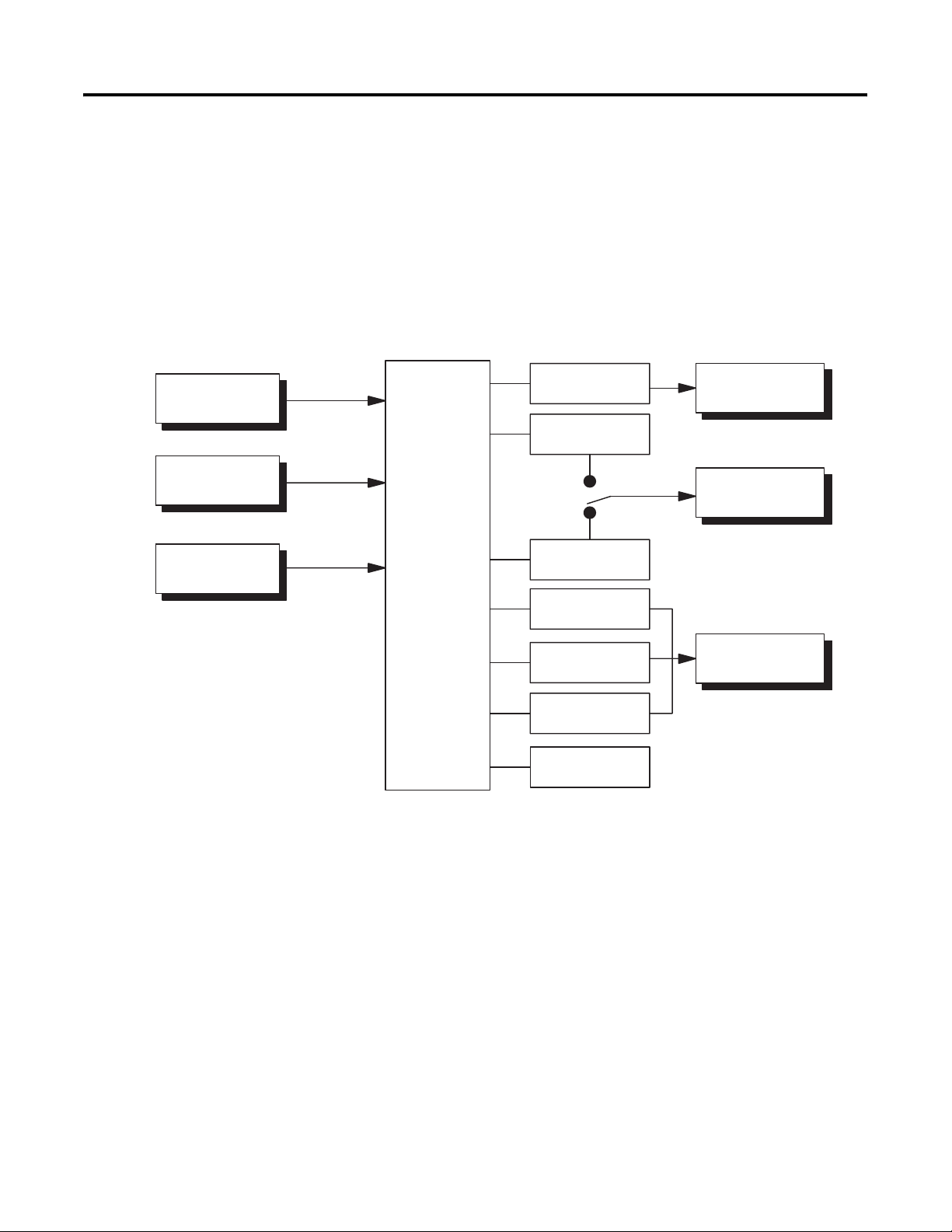
I/O Configuration and
Main Functions
Temperature input/
analog input
*HBA
CT input
*
Event input 2ch
SP input from external
digital switch function and
Run/Stop function
I/O Configuration
Figure 1.1
Controller
Control output 1
Control output 2
Heating and
cooling
Standard
Alarm 2
Alarm 1
Input error
HBA
OUT1
OUT2
ALM2
ALM1
HB
Control output 1
Alarm output 2
Alarm output 1
Communications
function
“*” marked items are options.
*
The Bulletin 900-TC16 allows the user to carry out the following:
•
Select from thermocouple and platinum RTD temperature sensors, plus
non-contact temperature sensor and analog input
•
Select heating and cooling control in addition to standard control
•
Select AT (auto-tuning) and ST (self-tuning) as tuning functions
• Use multi-SP and the RUN/STOP function according to event input
• Use the HBA (heater burnout alarm) function (when optional circuit
board Cat. No. 900-TC16EIM or 900-TC16COM is fitted)
1-1 Publication 900-UM001C-EN-E - January 2004
Page 14

1-2 Bulletin 900-TC16 Overview
• Use the communications function (when optional communications
board Cat. No. 900-TC16COM or 900-TC16ACCOM is fitted)
• Calibrate sensor input
• The Bulletin 900-TC16 features a watertight construction (NEMA4X:
equivalent to IP66).
• The Bulletin 900-TC16 conforms to cULus/IEC safety standards and
EMC standards.
Main Functions
The following introduces the main functions of the Bulletin 900-TC16. For
details on each function and how to use the functions, see Chapter 3 and
onward.
• Input Sensor Types — The following input sensors can be connected
for temperature input:
– Thermocouple: K, J, T, E, L, U, N, R, S, B
– Non-contact temperature sensor type: K (10…70°C), K
(60…120°C), K (115…165°C), K (160…260°C)
– Platinum resistance thermometer: Pt100, JPt100
– Analog input: 0…50 mV
• Control Output — The control output type is either an On/Off
electro-mechanical relay, On/Off voltage (solid-state relay) output, or
analog current (DC: 4...20 mA) output depending on the model of
Bulletin 900-TC16.
If you select the heating and cooling control method on the
Bulletin 900-TC16, alarm 2 output is used as the cooling output. Use
alarm 1 if an alarm is needed in heating and cooling control.
• Alarms — Alarms are supported on the Bulletin 900-TC16. You can
configure the alarm type and alarm value, or upper- and lower-limit
alarms.
Publication 900-UM001C-EN-E - January 2004
If necessary, a more comprehensive alarm function can be achieved by
setting the Standby Sequence, Alarm Hysteresis, Close in Alarm/Open
in Alarm, and Alarm Latch ON/OFF parameters.
When the input error output is set to ON, alarm output 1 turns ON
when an input error occurs.
Page 15

Bulletin 900-TC16 Overview 1-3
• Control Adjustment — Optimum PID constants can be configured
easily by AT (auto-tuning) and ST (self-tuning) functions.
• Event Input — When the optional event input unit Cat.
No. 900-TC16EIM is mounted in the Bulletin 900-TC16, the following
functions can be achieved by event input:
Multiple set point selection (multi-SP max. 4 points) and RUN/STOP
mode change.
• HBA — The heater burnout alarm (HBA) function is supported when
the optional unit (Cat. No. 900-TC16EIM or 900-TC16COM) is
mounted in the Bulletin 900-TC16.
• Communications Function — Communications to a personal computer
(PC) are supported when the optional communications unit Cat.
No. 900-TC16COM or 900-TC16ACCOM is mounted in the Bulletin
900-TC16. Communications are carried out over the RS-485 network
architecture. Note: The PC must have 900Builder software installed.
Hardware Versions
Table 1.A
DIN Size
(Dimensions)
(mm)
1/16 DIN
(48 x 48 x 78)
Power Supply
Voltage
100…240V AC 2
24V AC/DC 2
The following table provides the list of controller base features with associated
cat. nos.
No. of
Alarms
Supported
Control Output Type Controller Cat. No.
with Thermocouple
Support
Relay 900-TC16RTZ25 900-TC16RPZ25
Voltage output (for driving SSR) 900-TC16VTZ25 900-TC16VPZ25
4...20 mA analog 900-TC16ACTZ25 900-TC16ACPZ25
Relay 900-TC16RTU25 900-TC16RPU25
Voltage output (for driving SSR) 900-TC16VTU25 900-TC16VPU25
4...20 mA analog 900-TC16ACTU25 900-TC16ACPU25
Controller Cat. No.
with Platinum RTD
Support
Note: To implement the Heater Burnout Alarm (HBA) function, a current
transformer (Cat. No. 900-CT1 or 900-CT2) is required. A current
transformer is not provided with the controller.
Note: When the heating and cooling function or the heater burnout alarm is
used, one of the alarm outputs will be disabled for each function used.
Note: The heater burnout alarm is available by mounting the 900-TC16EIM
or the 900-TC16COM for the 900-TC16RTZ25, RPZ25, VTZ25, VPZ25,
RTU25, RPU25, VTU25, or VPU25.
Publication 900-UM001C-EN-E - January 2004
Page 16
1-4 Bulletin 900-TC16 Overview
Front Panel and LED Displays
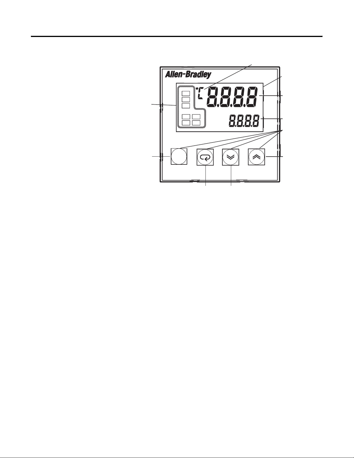
Figure 1.2
perational
rs
ndicato
Function
Group key
Display Meanings
Mode key Down key
Temperature unit
900-TC16
Displays/Indicators
No. 1 display
No. 2 display
Operations keys
Up key
• No. 1 Display — Displays the process value or parameter type.
• No. 2 Display — Displays the set point, manipulated variable, or
configured value (setup) of the parameter.
• Operational Indicators
– ALM1 (alarm 1)
Lights when alarm 1 output is ON.
– ALM2 (alarm 2)
Lights when alarm 2 output is ON.
– HB (heater burnout alarm display)
Lights when a heater burnout is detected.
– OUT1, OUT2 (control output 1, control output 2)
This operational indicator lights when control output 1 and/or
control output 2 are ON. Note, however, that OUT1 is out at all
times when control output 1 is current output.
Publication 900-UM001C-EN-E - January 2004
Page 17

Bulletin 900-TC16 Overview 1-5
– STOP
Lights when control of the Bulletin 900-TC16 has been stopped.
During control, this indicator lights when an event or the
RUN/STOP function has become stopped. Otherwise, this indicator
is out.
– CMW (communications writing control)
Lights when Communications Writing parameter/function is
“enabled” and is out when it is “disabled.”
• Temperature Unit — Temperature is displayed when the configured unit
used is set to a temperature (°C or °F). Indication is determined by the
currently selected “Temperature Unit” parameter value. When this
parameter is configured for °C, c is displayed, and when configured for
°F, f is displayed.
Basic Keypad Functions
The following describes the basic functions of the front panel keys.
• function group key — Press this key to select the desired function
groups. The function groups are selected in the following order:
“Operation function group” ←→ “Adjustment function group”,
“Initial Setting function group” ←→ “Communications Setting
function group”.
• M mode key — Press this key to select parameters within each function
group.
• U up key — Each press of this key increments the value displayed on
the No. 2 display. Holding down this key continuously increments the
value displayed.
• D down key — Each press of this key decrements the value displayed
on the No. 2 display. Holding down this key continuously decrements
the value displayed.
• + M key combination — This key combination sets the
Bulletin 900-TC16 to the “Protect function group.” For details on the
Protect function group, see Chapter 5 — Parameter Functions and
Definitions.
Publication 900-UM001C-EN-E - January 2004
Page 18

1-6 Bulletin 900-TC16 Overview
Notes:
Publication 900-UM001C-EN-E - January 2004
Page 19
Preparations
Chapter
2
Installation
48 48
x
Front View Side View Back View
58
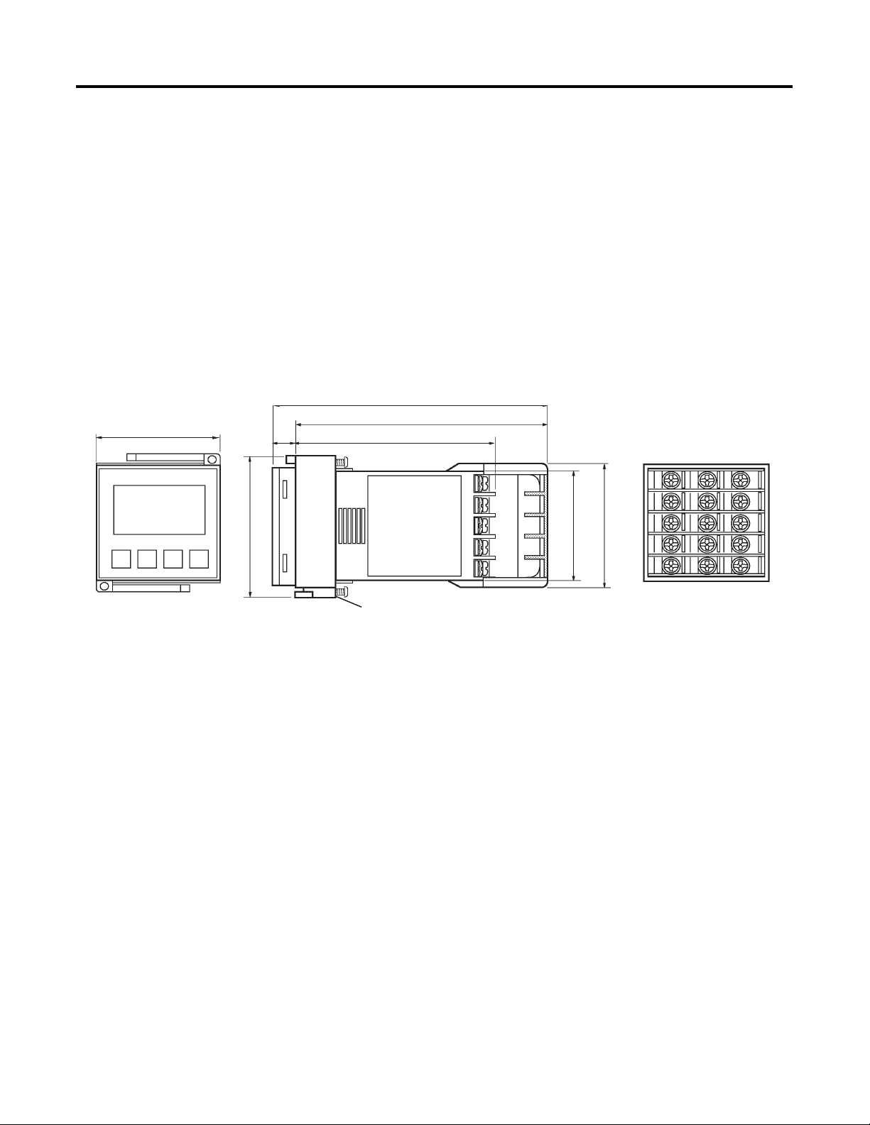
Approximate Dimensions
Dimensions are in millimeters. Dimensions are not intended to be used for
manufacturing purposes.
Note: To convert millimeters to inches, multiply by 0.0394.
Figure 2.1
93
9
78
Panel Mounting Adapter
44.844.8
x
48.8
1
2
3
4
5
11
6
12
7
13
8
14
9
15
10
2-1 Publication 900-UM001C-EN-E - January 2004
Page 20
2-2 Preparations
➍
60
min.
45
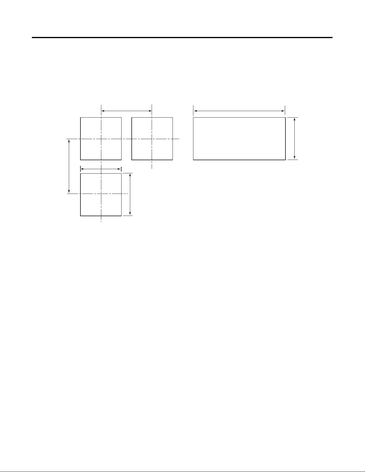
Panel Cutout
Dimensions are in millimeters. Dimensions are not intended to be used for
manufacturing purposes.
Figure 2.2
(48 number of units -2.5)
x60 min.
➊
45
➊
Horizontal Group Mounting of Controllers
(without Waterproofing ➌)
➋
➊
45
Individual Mounting (Vertical and Horizontal)
➊ Tolerance: +0.6…0.0 mm
➋ Tolerance: +1.0…0.0 mm
➌ This is a configuration in which the controllers are contiguously mounted (side by side). Therefore, the
➍ Maintain the specified mounting space between each controller. Controllers must not be group mounted
waterproof gasket cannot provide protection.
vertically.
• Horizontal group-mounting two or more temperature controllers, or
mounting temperature controllers above each other may cause heat to
build up inside the temperature controllers, which will shorten their
service life. When mounting temperature controllers like this, consider
forced cooling measures such as a cooling fan.
• If forced air cooling is used, limit cooling to the terminal block. Rapid
variation or transients in temperature at the terminal block may result in
a measurement error.
Publication 900-UM001C-EN-E - January 2004
Page 21
System Wiring and Installation Guidelines
Preparations 2-3
ATTENTION
!
ATTENTION
!
Risk of Electrical Shock
• Devices are Open Type, Listed Process Control
Equipment and must be mounted in an enclosure.
• More than one disconnect switch may be required to
de-energize the equipment before servicing.
• Signal inputs are SELV, limited energy.
• To reduce risk of fire or electrical shock, do not
interconnect the outputs of different Class 2 circuits.
• Disconnect all power (including field device) before
installing and/or servicing.
• Do not touch the controller’s wiring terminals while
the controller power is ON. Doing so may cause an
electric shock.
• Do not allow metal fragments or lead wire scraps to
fall inside the Bulletin 900-TC16 Temperature
Controller. These may cause electric shock, fire, or
malfunction.
• Never disassemble, repair, or modify the
Bulletin 900-TC16 Temperature Controller with line or
field device power applied. Doing so may cause electric
shock, fire, or malfunction.
• Do not use the Bulletin 900-TC16 Temperature
Controller in flammable and explosive gas
atmospheres.
• Use the Bulletin 900-TC16 Temperature Controller
within the rated supply voltage. Not doing so may
cause damage or fire.
• Configure all settings according to the control target. If
the configuration is not appropriate for the control
target, the Bulletin 900-TC16 Temperature Controller
may operate in an unexpected manner, resulting in
damage to the product or personal injury.
Publication 900-UM001C-EN-E - January 2004
Page 22
2-4 Preparations
ATTENTION
!
• To maintain safety in the event of a product
malfunction, always take appropriate safety measures,
such as installing an alarm on a separate power or
control line to prevent excessive temperature rise. If a
malfunction prevents proper control, an accident may
result.
• Do not wire unused terminals.
• Make sure to observe correct polarity when wiring the
controller terminals.
• Do not use the Bulletin 900-TC16 Temperature
Controller in the following places which might exceed
its specifications:
– Places subject to dust or corrosive gases (in
particular, sulfide gas, and ammonia gas)
– Places subject to high humidity, condensation, or
freezing
– Places subject to direct sunlight
– Places subject to vibration and large shocks
– Places subject to splashing liquid or oily atmosphere
– Places directly subject to heat radiated from heating
equipment
– Places subject to intense temperature changes
Publication 900-UM001C-EN-E - January 2004
• To allow heat to escape, do not block the area around
the Bulletin 900-TC16 Temperature Controller.
(Ensure that enough space is left for the heat to
escape.) Do not block the ventilation holes on the
casing.
• Cleaning: Do not use paint thinner or the equivalent.
Use standard grade alcohol to clean the
Bulletin 900-TC16 Temperature Controller.
• Power supply, input, output, and communication
terminals (for models with communications) have
basic insulation between them. When double insulation
is required, apply supplemental insulation defined in
IEC 60664 that is suitable for the maximum operating
voltage with clearances or solid insulation.
Page 23
Preparations 2-5
ATTENTION
!
• Attach a surge suppressor or noise filter to peripheral
devices that generate noise (in particular, motors,
transformers, solenoids, magnetic coils, or other
equipment that have an inductance component).
• Use within the following temperature and humidity
ranges:
Temperature: –10…+55°C,
Humidity: 25…85% (with no icing or condensation)
If the Bulletin 900-TC16 is installed inside a control
panel, the ambient temperature must be kept to under
55°C, including the temperature around the
Bulletin 900-TC16.
If the Bulletin 900-TC16 is subjected to heat radiation,
use a fan to cool the surface of the Bulletin 900-TC16
to under 55°C.
• Store within the following temperature and humidity
ranges:
Temperature: –25…+65°C,
Humidity: 25…85% (with no icing or condensation)
• Never place heavy objects on, or apply pressure to the
Bulletin 900-TC16 as it may cause it to deform and
deteriorate during use or storage.
• Avoid using the Bulletin 900-TC16 in places near a
radio, television set, or wireless installation. These
devices can cause radio disturbances which may
adversely affect the performance of the Bulletin
900-TC16.
Setting Up the Controller with the Optional Units
If RS-485 communications, event input, and heater burnout functions are
required, mount the communications unit (Cat. No. 900-TC16COM) or the
event input unit (Cat. No. 900-TC16EIM) in the Bulletin 900-TC16 controller.
Publication 900-UM001C-EN-E - January 2004
Page 24
2-6 Preparations
Option Units
If heater burnout is not required or if you are using a controller with analog
output, use the 900-TC16ACCOM or 900-TC16ACEIM option unit.
Table 2.A
Name Cat. No. ➊ Function
RS-485 Communications
and heater burnout unit
900-TC16COM ➋ RS-485 Communications
with heater burnout function
RS-485 Communications
900-TC16ACCOM ➋ RS-485 Communications
unit
Event input unit and heater
burnout
900-TC16EIM ➋ Event input with heater
burnout function
Event input unit 900-TC16ACEIM ➋ Event input
➊ One (1) option unit per controller.
➋ The option unit provides optical isolation (approximately 32V DC) between the controller electronics and the
field input.
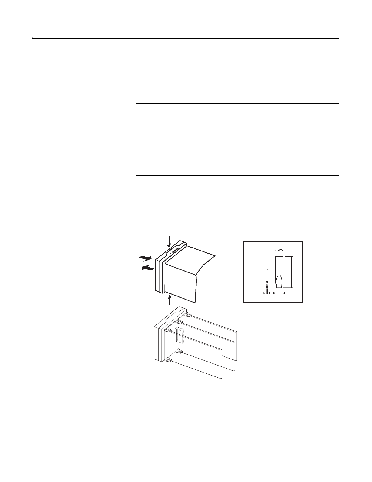
Installing the Option Unit/Board in the Controller
Figure 2.3
(1)
(4)
(2)
(1)
Regular
screwdriver
(units: mm)
20 min.
Publication 900-UM001C-EN-E - January 2004
(3)
Note: When you remove the internal mechanism from the housing, never
touch electric components inside or subject the internal mechanism to shock.
Page 25
Preparations 2-7
1. Insert the two regular flat-bladed screwdrivers (see drawing above) into
the slots (one on the top and one on the bottom) to release the
controller case locking hooks.
2. Insert the screwdriver into the gap between the front case and rear case,
and slightly draw out the front panel. Then, using your hands, gently
remove the front (LED) case from the rear case (with terminal block).
Note: Ensure you take note of the front and rear case orientation
before removing the two parts. The parts will not go together if
assembled incorrectly. However, if excessive force is applied, damage
could result.
3. Install the option unit: Match the upper and lower circuit board locking
claws with the option board connection points and insert the option
unit. The option unit mounts in the center position.
4. Before you push the unit back into the case, make sure that the water
tight packing is in place. Push the unit back into the rear case until you
hear a click. When you do this, hold down the hooks on the top and
bottom of the rear case so that they are firmly hooked in place.
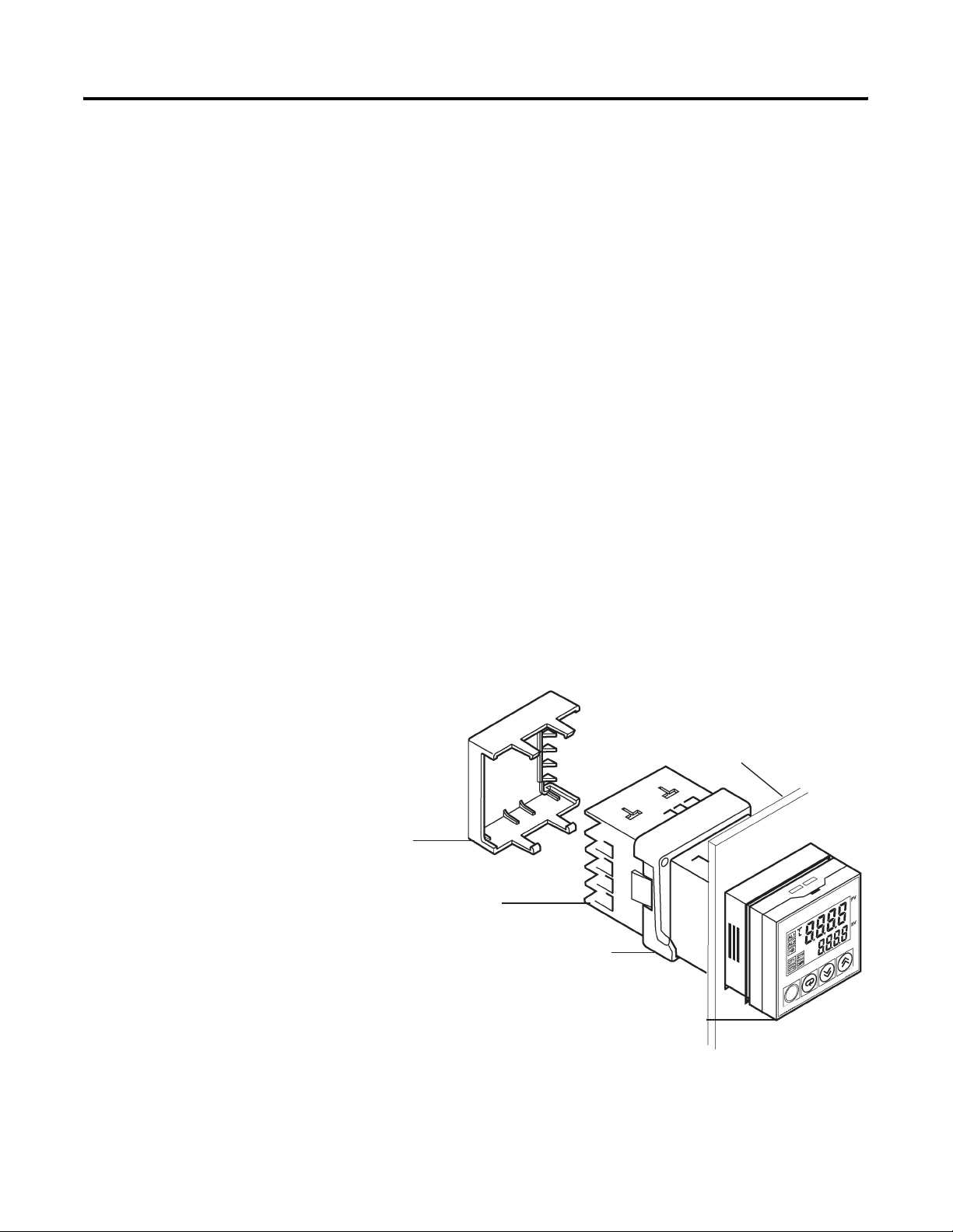
Panel Mounting
Figure 2.4
Safety Terminal
Block Cover
➊
Rear Case
Terminal Block
➊ Per VDE 0106
Panel Mounting
Adaptor
Panel
Front Case
Publication 900-UM001C-EN-E - January 2004
Page 26

2-8 Preparations
How to Attach the Bulletin 900-TC16 on the Panel
1. Insert the controller through the hole in the panel from the front, and
push the panel mounting adapter on from the rear. Push the adapter up
to the back of the panel ensuring that the controller is pushed all the way
in, removing any gap between the controller, panel, and adapter. Finally,
use the two screws on the adapter to secure the unit in place. The
recommended panel thickness is 1…5 mm.
2. To mount the Bulletin 900-TC16 so that it is waterproof, insert the
waterproof packing on the Bulletin 900-TC16. The Bulletin 900-TC16
cannot be waterproofed when it is group-mounted in the horizontal
fashion shown in Figure 2.1.
3. Maintain the specified mounting space between each controller.
4. When two or more Bulletin 900-TC16s are mounted together, make
sure that the surrounding ambient temperature does not exceed the
allowable specified operating temperature of 55°C.
5. Tighten the two screws on the adapter against the panel. Tighten the
two screws alternately keeping the torque to approximately
0.29…0.39 Nm (2.57…3.45 lb-in.).
6. To allow heat to escape, do not block the area around the
Bulletin 900-TC32 Temperature Controller. (Ensure that enough space
is left for the heat to escape.) Do not block the ventilation holes on the
casing.
7. Allow as much space as possible between the Bulletin 900-TC32 and
devices that generate powerful high-frequency noise (e.g.,
high-frequency welders, high-frequency sewing machines) or surges.
8. Install the controller so that it is horizontal (can read the display
properly).
How to Attach the Wiring Terminal Block Cover
Make sure that the UP mark on the adapter is facing up, and then fit the
terminal cover into the holes on the top and bottom. The Bulletin 900-TC16 is
provided with a protective terminal block cover (finger protection per
VDE 0106).
Publication 900-UM001C-EN-E - January 2004
Page 27
Preparations 2-9
Bulletin 900-TC16 Wiring Terminals
+
Voltage output/relay
output/Current output
Control output 1
A
-
B
Analog input
B
+
Pt
Input power supply required: 100…240V AC
-
-
+
TC
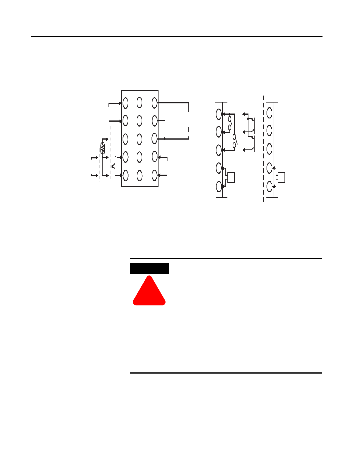
Terminal Arrangement
Figure 2.5
(Rear of Case)
Alarm output
1
11
6
2
12
7
ALM1/heater
burnout
3
13
8
4
14
9
/Input error
Input power supply
5
15
10
Event input/CT Communications/CT
ALM2/
Control output2
and HBA and HBA
11
EV1
EV1
12
EV2
+
EV2
13
+
14
CT CT
15
900-TC16EIM 900-TC16COM
11
12
13
14
15
No. Cat. No. Cat.
RS–485
B(+)
A(–)
Do not
use
Wiring Guidelines and Precautions
ATTENTION
!
• Separate input leads and power lines in order to protect the
Bulletin 900-TC16 and its low voltage sensor (e.g., TC) and
communication lines from external noise.
• Do not wire unused terminals.
• To reduce the effects of induced electrical noise, keep
the high-voltage or large-current power lines as far
away as possible from signal (low-voltage) lines, and
avoid parallel or common wiring with the power lines
when you are wiring to the terminals. We recommend
using separating pipes, ducts, or shielded lines.
• Allow as much space as possible between the Bulletin
900-TC16 and devices that generate powerful
high-frequency noise (e.g., high-frequency welders,
high-frequency sewing machines) or surges.
• Make sure to observe correct polarity when wiring the
controller terminals.
Publication 900-UM001C-EN-E - January 2004
Page 28
2-10 Preparations
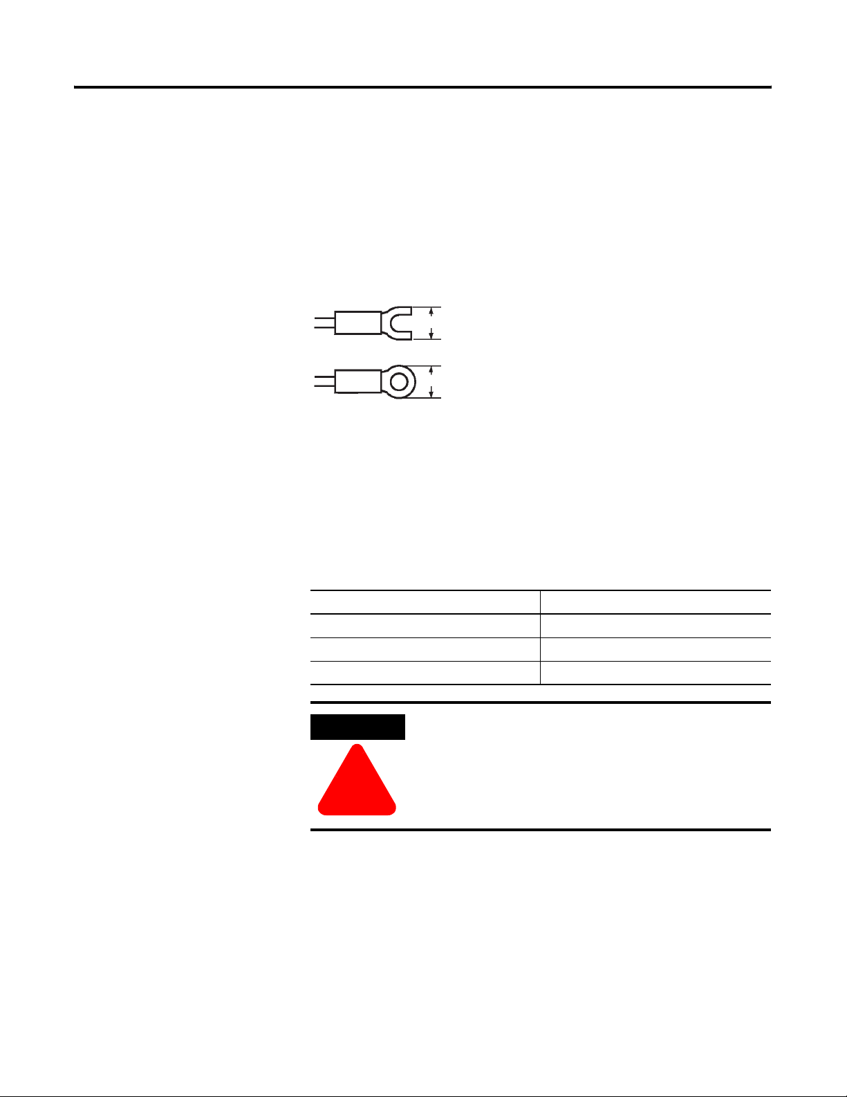
• We recommend using solderless lugs (see Figure 2.6) when wiring the
Bulletin 900-TC16. However, if lugs are not used, the controller’s screw
terminals will accept two solid or stranded wires (no mixing) between
24…14 AWG.
• Tighten the terminal block’s screws using a torque 1.13…1.36 Nm
(10…12 lb-in.). Loose screws may result in the wires falling off, causing
a malfunction.
• Use the following type of solderless lugs for M3.5 screws.
Figure 2.6
7.2 mm max.
7.2 mm max.
Wiring
Power Supply
The controller requires an external power source for operation. Connect to
terminals 9 and 10. The following table shows the specification of the external
supply.
Table 2.B
Input Power Supply Bulletin 900-TC16 Power Usage
100…240V AC, 50/60 Hz 4.7 VA @ 120V AC, 7 VA @ 240V AC
24V AC, 50/60 Hz 4 VA
24V DC (not polarity sensitive) 3 W
ATTENTION
Use a power supply matched to the power specifications of
the Bulletin 900-TC16. Also, make sure that rated voltage is
attained within 2 seconds of turning the power ON.
!
When mounting a noise filter on the power supply, make sure to first check the
filter’s voltage and current capacity, and then mount the filter as close as
possible to the Bulletin 900-TC16.
Publication 900-UM001C-EN-E - January 2004
Standard insulation is applied to the power supply I/O sections. If reinforced
insulation is required, connect the input and output terminals to a device
without any exposed current-carrying parts or to a device with standard
insulation suitable for the maximum operating voltage of the power supply
I/O section.
Page 29
Preparations 2-11
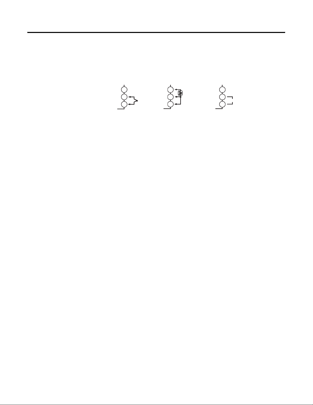
Wiring Input/Sensor Devices
Connect sensors to terminals 3…5 as follows according to the input/sensor
type.
Figure 2.7
3
-
4
5
+
Thermocouple
3
4
5
thermometer
A
B
B
Platinum resistance
3
4
5
Analog
input
-
v
+
Input/Sensor Wiring Considerations
• When it is necessary to extend the thermocouple leads, make sure to use
thermocouple extension wire matched to the type of thermocouple.
• For a thermocouple, make sure to follow the polarity color code
convention.
• If there is a large error in the measurement values, make sure that input
compensation has been properly configured.
• RTDs can be either 2- or 3-wire types. If a 3-wire type is used, the
controller provides lead wire resistance compensation up to 5 Ω
resistance. If using 24 AWG lead wire, this is approximately 59 m of
wire. Use larger gauge wire if longer length is required.
• For RTDs, the controller source is approximately 1 mA of current.
• If a cooling fan is used in the panel enclosure, prevent only the terminal
block from being cooled when using thermocouples. Otherwise, this
may result in a measurement error.
• To reduce induced electrical noise, the leads on the temperature
controller’s terminal block must be wired separately from
large-voltage/large-current power leads. Also, avoid wiring leads in
parallel with power leads or in the same wiring path. Other methods
such as separating conduits and wiring ducts, or using shield wire are
also effective.
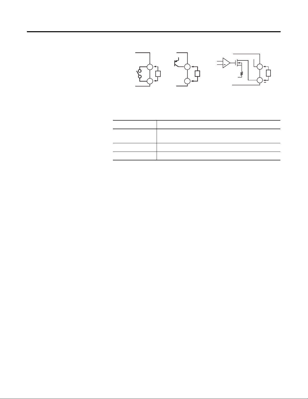
Wiring Control Output 1
Terminals 1 and 2 are for control output 1. The following diagrams show the
available hard contact, fixed voltage (SSR) or analog outputs and their internal
equalizing circuits.
Publication 900-UM001C-EN-E - January 2004
Page 30
2-12 Preparations
Figure 2.8
Temperature
controller
Relay
+V
+
1
L
2
1
2
GND
Voltage (SSR)
L
GND
Current
+V
+
1
L
2
The following table shows the specifications for each output type.
Table 2.C
Output Type Specifications
Relay 3 A @ 250V AC, 10 A @ 30V AC (max. resistive load), 5V, 10 mA
(min. resistive load) electrical life: 100,000 operations
Voltage (PNP) PNP type, 12V DC, 21 mA (with over-current limit protection)
Current DC: 4...20 mA, Load: 600 ohms max., Resolution: approx. 2,600
Output Wiring Considerations
• The PNP voltage output (control output) is not electrically isolated from
the controller’s internal circuits. When using a grounded thermocouple,
do not connect the control output terminals to ground. If the control
output terminals are connected to ground, errors will occur in the
measured temperature values as a result of ground loop leakage current.
• The 4...20 mA analog output is electrically isolated from the other
controller circuits as follows:
– Analog Output to Sensor Input: 500 VAC 50/60 Hz for 1 minute
– Analog Output to Alarm Output: 2000 VAC 50/60 Hz for 1 minute
– Analog Output to Input Power Supply: 2000 VAC 50/60 Hz for 1
minute
• The life expectancy of the output relays varies greatly with the switching
capacity and other switching conditions. Always use the output relays
within their rated load and electrical life expectancy. If an output relay is
used beyond its life expectancy, its contacts may become fused or
burned.
• Use the Bulletin 900-TC16 Temperature Controller outputs within the
rated load. Not doing so may cause damage or fire.
• Attach a surge suppressor or noise filter to peripheral devices that
generate noise (in particular, motors, transformers, solenoids, magnetic
coils, or other equipment that have an inductance component).
Publication 900-UM001C-EN-E - January 2004
• About 4 seconds are required for control and/or alarm outputs to turn
ON when the controller power is turned ON. Take this into
consideration when the temperature controller is incorporated into a
sequence circuit.
Page 31
Preparations 2-13
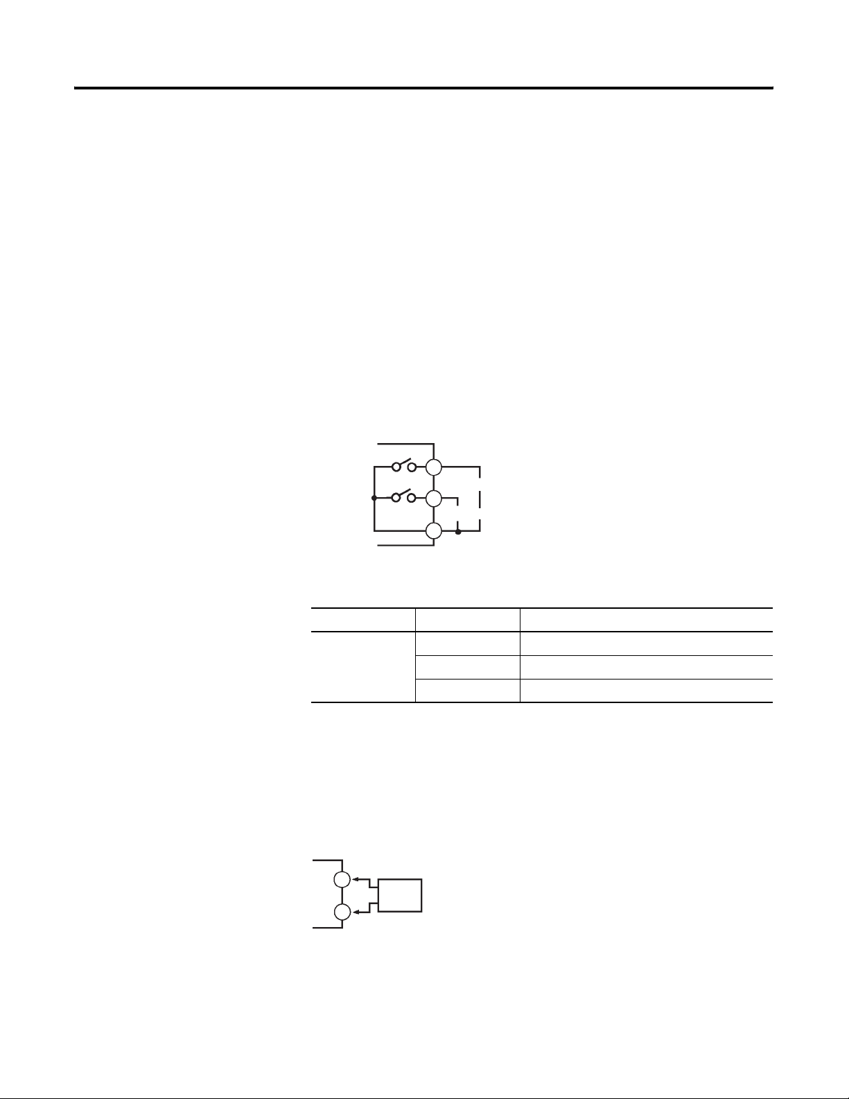
Wiring Alarm Output 1 and Alarm/Control Output 2
• On the Bulletin 900-TC16, Alarm Output 1 (ALM1) is across
terminals 7 and 8, and Alarm Output 2 (ALM2) is across terminals 6
and 8. When heating and cooling control is used, Alarm Output 2
becomes the cooling output (Control Output 2).
• When the Input Error Output parameter is configured to ON, alarm
output 1 turns ON when an input error occurs.
• When the option unit (Cat. No. 900-TC16EIM or 900-TC16COM) is
mounted in the Bulletin 900-TC16, an OR of alarm output 1 and the
Heater Burnout alarm will result. To disable alarm output 1 and output
only the Heater Burnout alarm on terminals 7 and 8, configure the
mode of the alarm output 1 to the value 0 (not active selection).
• The equivalent circuits for terminals 6…8 are shown in the following
diagram.
Figure 2.9
Controller
6
ALM2/Control OUT2
7
ALM1/heater burnout alarm/Input error
8
• Controller alarm relay specifications are as follows:
Table 2.D
Type Voltage Steady-State Resistive Current
SPST-NO 250V AC 1 A (max. resistive load)
30V DC 2 A (max. resistive load)
1V 1 mA (min. resistive load)
Wiring the Current Transformer (CT) Input (Heater Burnout Alarm Function)
• When the option unit (Cat. No. 900-TC16COM or 900-TC16EIM) is
mounted on the Bulletin 900-TC16 and the Heater Burnout function is
used, connect a current transformer (CT) across terminals 14 and 15.
For CT dimensions, see p. A-4, Approximate External Dimensions.
Figure 2.10
14
15
CT
Publication 900-UM001C-EN-E - January 2004
Page 32
2-14 Preparations
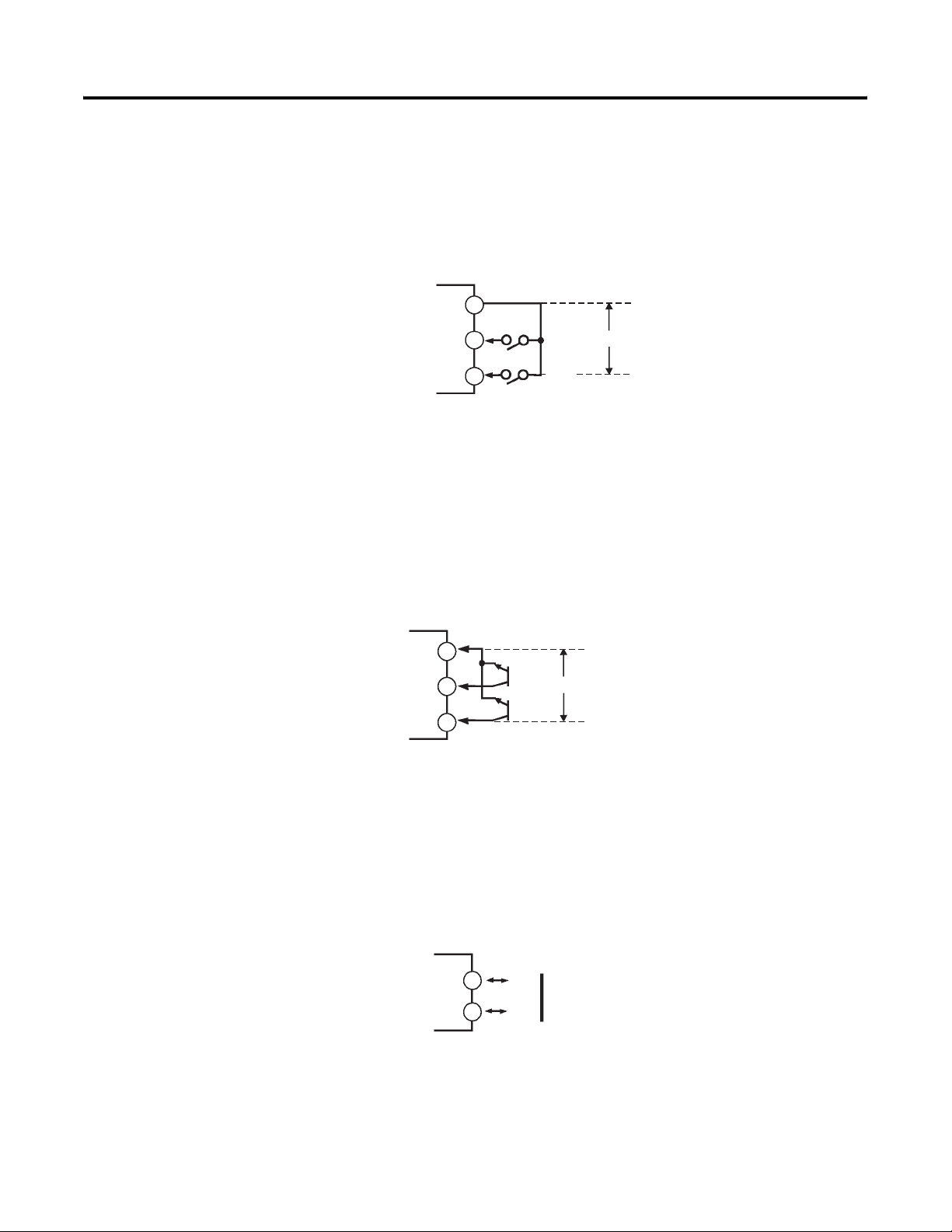
Wiring the Event Input
When the option event input unit Cat. No. 900-TC16EIM or
900-TC16ACEIM is mounted in the Bulletin 900-TC16 and the event input
function is possible by connecting devices to terminals 11…13.
Figure 2.11
Temperature
controller
11
12
13
EV1
EV2
Do not apply an external voltage source
Note:
to the Event Input Terminals.
Use event inputs under the following conditions:
• The output current from the controller is approximately 7 mA @ 5V.
• Contact input ON: 1 KΩ max., OFF: 100 KΩ min.
• No-contact input ON: residual voltage 1.5V max., OFF: leakage current
0.1 mA max.
Polarities using non-contact inputs are as follows:
Figure 2.12
Temperature
Controller
11
12
13
EV1
+
EV2
+
Do not apply an external voltage source
Note:
to the Event Input Terminals.
Wiring Communications to a Personal Computer (Requires 900Builder
Software)
Publication 900-UM001C-EN-E - January 2004
When the option communications unit Cat. No. 900-TC16COM or
900-TC16ACCOM is mounted in the Bulletin 900-TC16 for communicating
with a PC, connect the RS-485 communications cable across terminals 11 and
12.
Figure 2.13
Temperature
controller
11
12
B(+)
RS-485
A(–)
Page 33
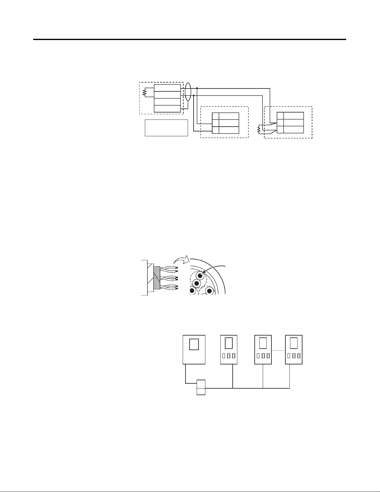
Figure 2.14 Communication Unit Wiring Diagram
PC with RS-232
to RS-485 Converter
such as 900-CONV Shielded cable
-
+
900-TCx (No.1)
FG
A<B : “1” mark
A>B : “2” space
RS-485
No
Abbr.
A(–)12
B(+)11
Preparations 2-15
900-TCx (No.31)
RS-485
No
Abbr.
A(–)12
B(+)11
Terminator
(120 Ω
, 1/2 W)
• The RS-485 connection can be either one-to-one to one-to-N. Up to 32
units including the personal computer can be connected in one-to-N
systems. Use shielded, twisted pair cable (24…14 AWG) and keep the
total cable length within 500 m.
• Specify both ends of the transmission path including the PC as the end
node (that is, connect terminating resistors to both ends).
The maximum terminal resistance is 54 Ω (see Figures 2.13 and 2.14).
• The first and last device in the link must be terminated with a 120 Ω,
1/2 W resistor.
Figure 2.15
AWG24 min.
Conductor area cross-section
0.08042mm
2
min.
• To use a PC on an RS-485 link/network connection, a Bulletin
900-CONV RS-232-to-RS-485 or equivalent converter is required.
Figure 2.16
900-TC16900-TC16
PC
RS-232
RS-485
900-CONV
Note: The PC must have 900Builder software installed to configure/monitor
the Bulletin 900-TC16 controller(s).
Publication 900-UM001C-EN-E - January 2004
Page 34

2-16 Preparations
Notes:
Publication 900-UM001C-EN-E - January 2004
Page 35
Configuration and Basic Operation
n
Chapter
3
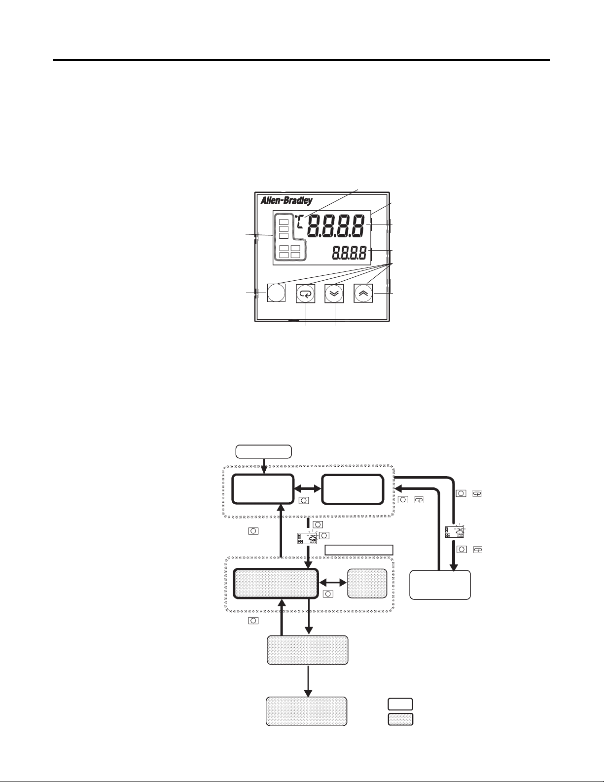
How Function Groups Are Configured and Operating the Keys on the Front Panel
Figure 3.1
perational
s
dicator
Function
Group key
Mode key Down key
Temperature unit
900-TC16
Displays/Indicators
No. 1 display
No. 2 display
Operations keys
Up key
Parameters are divided into control categories, each called a function group.
Each of the items/values that can be configured in these function groups is
called a parameter. The function groups on the Bulletin 900-TC16 are divided
into the following:
Figure 3.2
Power ON
Operation
function group
Less than
1 second
key
1 second min.
Initial setting
function group
key
1 second min.
Advanced setting
function group
Calibration
function group
Adjustment
function group
key
3 seconds min.key
key
The PV display flashes after one second.
Control stops.
Communications
setting
function group
key
Less than
1 second
Password input
set value “-169”
Note :
Communications setting level is displayed
when the optional communication unit
Password input
set value “1201”
Cat. No. 900-TC16COM is mounted.
+ key
1 second min.
Protect
function group
Control in progress
Control stopped
+ key
The PV display
flashes
+ key
3 seconds min.
3-1 Publication 900-UM001C-EN-E - January 2004
Page 36
3-2 Configuration and Basic Operation
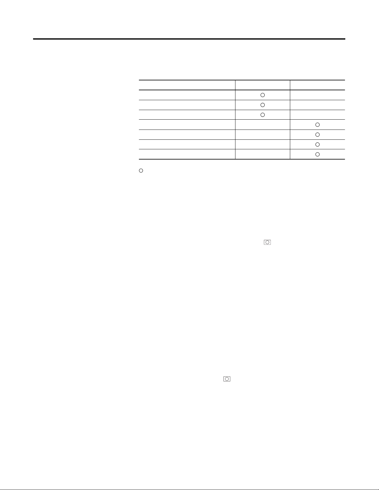
Table 3.A
Control Category Control in Progress Control Stopped
Protect function group —
Operation function group —
Adjustment function group —
Initial Setting function group —
Advanced Setting function group —
Calibration function group —
Communications Setting function group —
Indicates items can be configured.
Of these control categories, the Initial Setting function group,
Communications Setting function group, Advanced Setting function group,
and Calibration function group can be used only when control has stopped.
Note that controller outputs are stopped/reset when any of these four
function groups are selected.
• Protect Function Group — To move the control category to this
function group, simultaneously press the and M keys for at least
3 seconds in the Operation function group or Adjustment function
group. This function group is used to prevent unwanted or accidental
modification of parameters. Protected parameters will not be displayed,
and so the parameters in that function group cannot be modified.
• Operation Function Group — This control category is displayed
when you turn the power to the controller ON. You can move to the
Protect function group, Initial Setting function group, and Adjustment
function group from this function group.
Normally, select this function group during operation. During
operation, the process value (PV), set point (SP), and manipulated
variable (MV) can be monitored, and the alarm value and upper- and
lower-limit alarms can be monitored and modified.
• Adjustment Function Group — To move the control category to this
function group, press the key for less than 1 second.
This function group allows you to enter control parameters. This
function group contains parameters for setting the AT (auto-tuning),
communications writing enable/disable, hysteresis, multi-SP, input shift
values, heater burnout alarm (HBA), and PID constants. You can move
Publication 900-UM001C-EN-E - January 2004
Page 37

Configuration and Basic Operation 3-3
to the top parameter of the Initial Setting function group and Operation
function group from here.
• Initial Setting Function Group — To move to this function group,
press the key for at least 3 seconds in the Operation function group
or Adjustment function group. The PV display flashes after 1 second.
This function group is for specifying the input type, selecting the
control mode, control period, setting direct/reverse action, and alarm
type. You can move to the Advanced Setting function group or
Communications Setting function group from this function group. To
return to the Operation function group, press the key for at least
1 second. To move to the Communications Setup function group, press
the key for less than 1 second.
• Advanced Setting Function Group — To select this function group,
you must enter the password (–169) in the Initial Setting function group.
You can move to the Calibration function group only from this function
group.
This function group is for configuring the automatic return of display
mode, MV limitter, event input assignment, standby sequence, alarm
hysteresis, ST (self-tuning), and for moving to the user Calibration
function group.
• Communications Setting Function Group — To move to this
function group, press the key for less than 1 second in the Initial
Setting function group. When the communications function is used, set
the communications conditions in this function group. Communicating
with a PC allows set points to be read and written, and manipulated
variables to be monitored.
Note: This function group is available if the optional communications
card (Cat. No. 900-TC16COM or 900-TC16ACCOM) is fitted in the
unit.
• Calibration Function Group — To move to this function group, you
must enter the password (1201) in the Advanced Setting function group.
This function group allows you to configure an offset deviation for the
input circuit.
You cannot move to other function groups from this function group by
operating the keys on the front panel. To cancel this function group,
turn the controller’s power OFF then back ON again.
Publication 900-UM001C-EN-E - January 2004
Page 38
3-4 Configuration and Basic Operation
Selecting Parameters
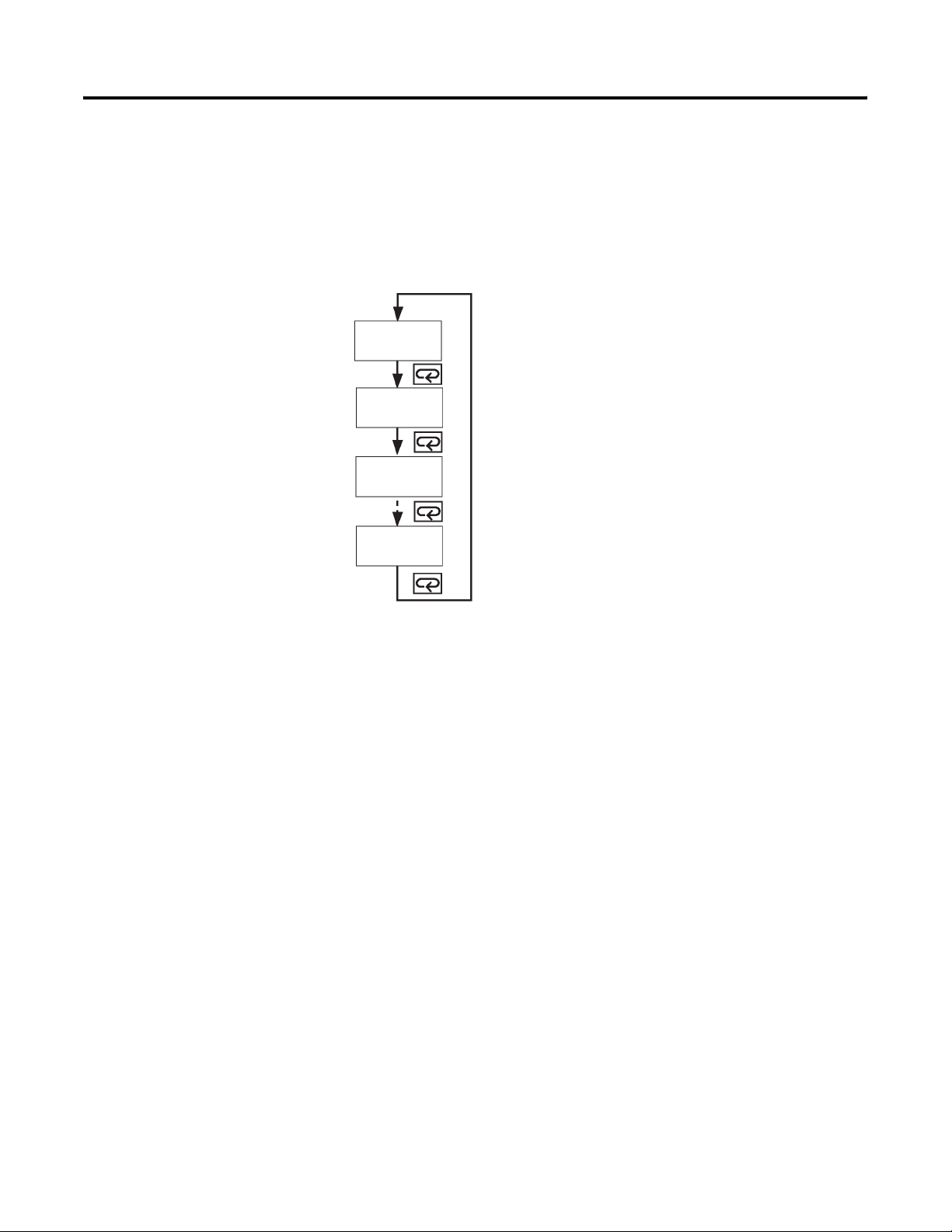
To select the various parameters in each function group, press the M key.
Each press of the M key advances to the next parameter. For details on each
parameter, see Chapter 5 — Parameter Functions and Definitions.
Figure 3.3
Parameter
1
Parameter
2
Parameter
3
Parameter
n
Changing Parameters and Loading Values into Controller Memory
If you press the M key at the final parameter, the display returns to the top
parameter for the current function group.
To change the parameters value or configuration (setup), modify the setting by
using the U or D key, and either leave the setting alone/unchanged for at
least 2 seconds or press the M key. This loads the present value displayed into
controller memory.
When another function group is selected, the parameter and value on the
display are the ones currently loaded into memory.
Before you turn controller power OFF, you must first load the values or
parameters setup (by pressing the M key). The values and parameters setup
are sometimes not changed by merely pressing the U or D key.
Publication 900-UM001C-EN-E - January 2004
Page 39
Configuration and Basic Operation 3-5
Communications Function
The Bulletin 900-TC16 can be provided with a communications function that
allows you to monitor and configure controller parameters from a PC that has
900Builder software installed. If the communications function is required,
mount the optional circuit board (Cat. No. 900-TC16COM or
900-TC16ACCOM) into the Bulletin 900-TC16.
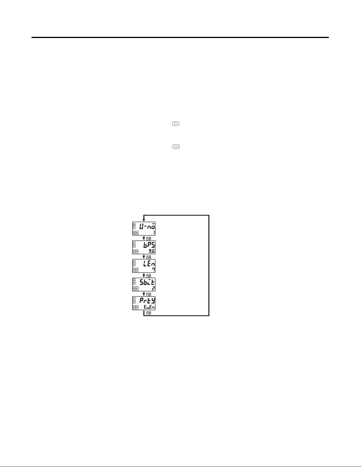
Follow the procedure below to move to the Communications Setting function
group.
1. Press the key for at least 3 seconds in the Operation function group.
This moves you to the Initial Setting function group.
2. Press the key for less than 1 second. The Initial Setting function
group moves to the Communications Setting function group.
3. Pressing the M key advances the parameters as shown in the following
figure.
4. Press the U or D key to change the configuration of any parameter
value.
Figure 3.4
Communications
Unit No.
Baud rate
Data bit
Stop bit
Parity
Publication 900-UM001C-EN-E - January 2004
Page 40

3-6 Configuration and Basic Operation
Setting up Communications Parameter Data
Set the Bulletin 900-TC16 communications parameter specifications so that
they match the communication parameter setup for the personal computer
using 900Builder software. In a multidrop (RS-485) 1:N configuration, match
the setting data except the communications unit numbers on all units. Unique
communications unit numbers must be configured for each controller/device
in an RS-485 system.
Table 3.B
Initial Setup Examples
Parameter Displayed
Characters
Communications Unit No. u-no 0…99 1 None
Baud Rate bps 1.2, 2.4, 4.8, 9.6,
Data Bit len 7, 8 7 bit
Stop Bit sbit 1, 2 2 bit
Parity prty None, even, odd Even None
Configurable
(Monitor) Value
19.2
Default
Value
9.6 kbps
Units
The and M keys are used to switch between configuration menus, and the
amount of time that you hold the keys down determines which configuration
menu you move to. This section describes two typical examples.
Publication 900-UM001C-EN-E - January 2004
Page 41
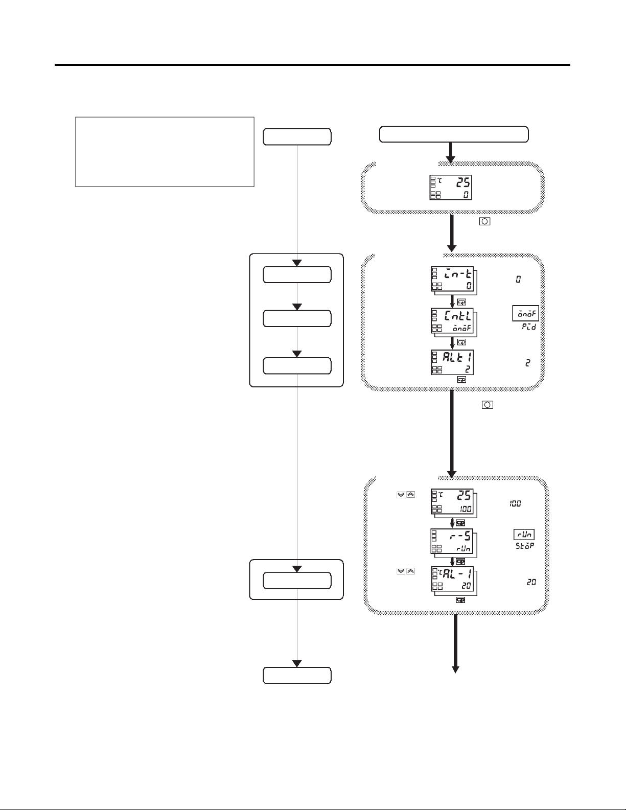
Figure 3.5 Typical Example
Alteration Overview:
Input type : 0 = K thermocouple -200…1300°C
Control method : On/Off Control
Alarm type : 2 upper limit
Alarm value 1 : 20°C deviation
Set point : 100°C
Initial setting
function group
Setup procedure
Power ON
Configuration and Basic Operation 3-7
Operation
function group
Initial setting
function group
Power ON
Process value/
set point
Press key for at least
three seconds.
Control stops.
Set input specifications
Set control specifications
Operation
function group
Set alarm type
Check input type.
Check that control
is ON/OFF control.
Check alarm type.
Operation
function group
Press keys
to set point to
"100°C".
Make sure that
control is running.
Input type
In ON/OFF
control
In PID control
Alarm 1 type
Press key for at
least one second
Process value/
set point
During run
During stop
Set alarm values
Start operation
Press keys
to set alarm value
to "20°C".
Publication 900-UM001C-EN-E - January 2004
Alarm value 1
Start operation
Page 42
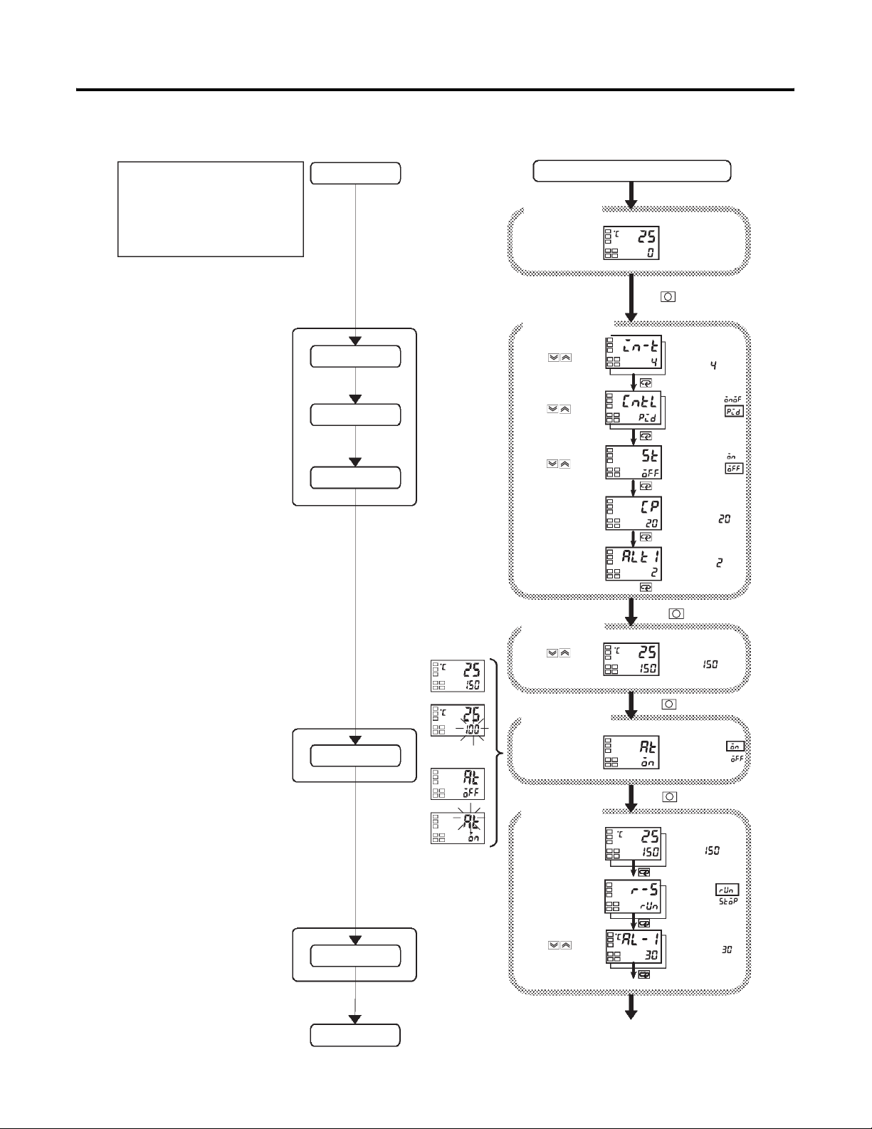
3-8 Configuration and Basic Operation
Alteration Overview:
Input type : 4 = T thermocouple -200°…400°C
Control method : PID control
Calculate PID constants by AT (auto tuning) execution.
Alarm type : 2 upper limit
Alarm value 1 : 30°C (deviation)
Set point : 150°C
Initial setting
function group
Figure 3.6 Typical Example 2
Setup procedure
Power ON
Operation
function group
Initial setting
function group
Power ON
Process value/
set point
Press key for at least
three seconds.
Control stops.
Set input specifications
Set control specifications
Adjustment
function group
Set alarm type
AT execution
PV/ST
After AT execution
During AT execution
While AT is being
executed SP will flash
After AT execution
Press keys
to select input type.
Press keys
to select PID control.
Press keys
to set ST to OFF.
Check the
control period.
Check alarm type.
Operation
function group
Press keys
to set point to
"150°C".
Adjustment
function group
Execute AT
(auto tuning).
Input type
In ON/OFF
control
In PID control
To execute ST
To cancel ST
Control period (heat)
(unit: seconds)
Alarm 1 type
Press key for at least one second
Process value/
set point
Press key for less than one second
To execute AT
To cancel AT
Operation
function group
Publication 900-UM001C-EN-E - January 2004
(when PID control
is selected)
Set alarm values
Start operation
During AT execution
Operation
function group
Make sure that
set point is 150°C.
Make sure that
control is running.
Press keys
to set alarm value to
"30°C".
Press key for less than one second
Start program execution
Process value/
set point
During run
During stop
Alarm value 1
Page 43
Configuration and Basic Operation 3-9
Configuring the Input Type
The Bulletin 900-TC16 supports four input/sensor types: platinum Resistance
Temperature Detector (RTD), thermocouple, non-contact temperature sensor,
and 0…50 mV analog input. To configure the controller input type refer to the
appropriate sensor in the Input Type parameter (see Table A.D, List of Input
Types) and use the Set Value number that matches the sensor. The
Bulletin 900-TC16 general controller specifications support two types of
inputs, platinum resistance thermometer input types and thermocouple input
type, whose set values differ. Check the cat. no. of your Bulletin 900-TC16 at
purchase to ensure it matches your input requirements (see Table 1.A).
Input Type
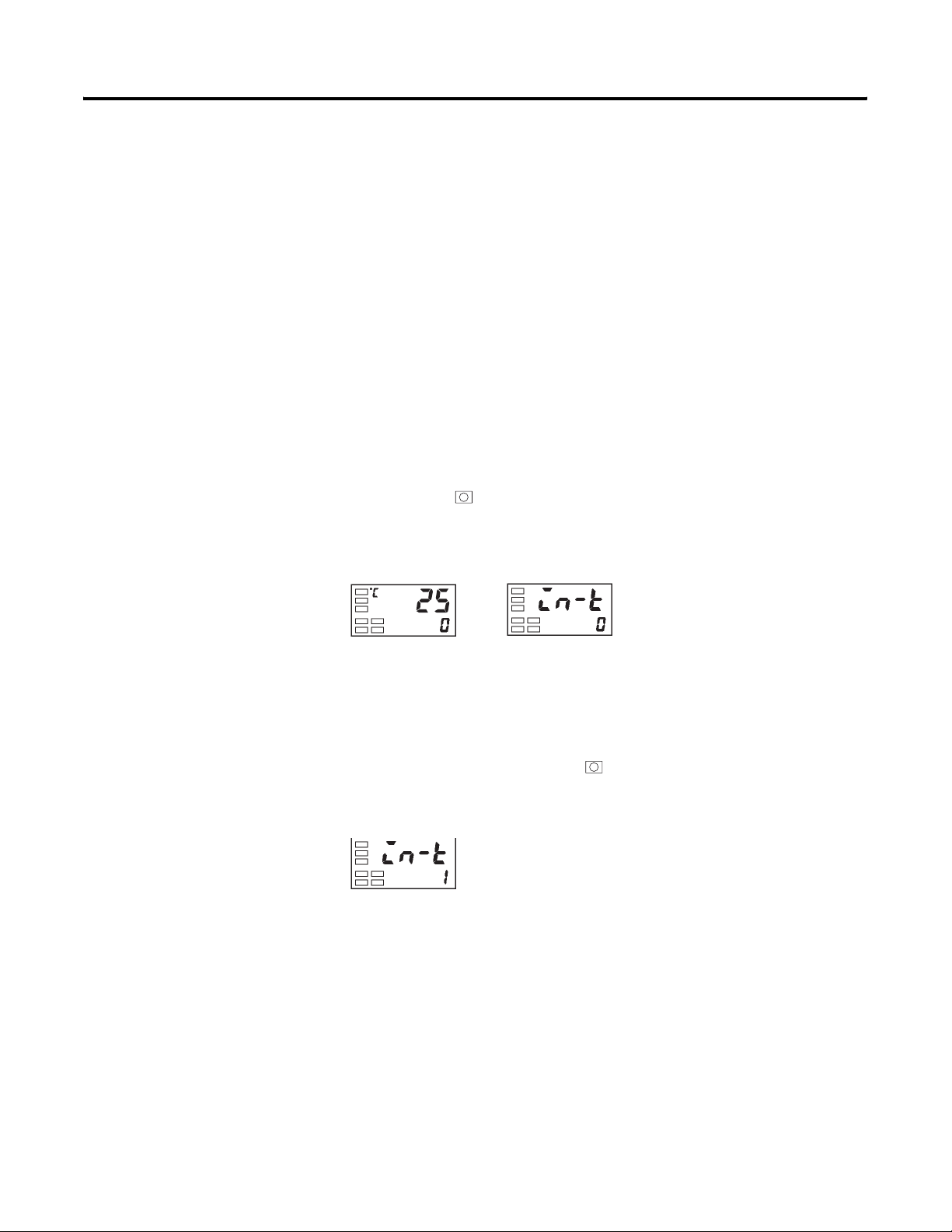
Example Operation Procedure — Configure the Input Type for Type K
Thermocouple –20.0…500.0°C
1. Press the key for at least 3 seconds to move from the Operation
function group to the Initial Setting function group.
Figure 3.7
Operation function group
Initial setting level
Input type
Selecting °C/°F
2. Press the U key to configure the Set Value of the desired sensor. When
you use a type K thermocouple (–20.0…+500.0°C), enter 1 as the value.
Note: The Set Value is loaded into the controller memory if you do not
operate the keys on the front panel for 2 seconds after changing the
parameter, or by pressing the or M keys. This applies to changing all
values and/or parameters.
Figure 3.8
Temperature Unit
Selecting temperature units (°C/°F) is easily configurable from the keypad.
Configure the temperature unit in the Temperature Unit parameter of the
Initial Setting function group. Note: The default is °C.
Publication 900-UM001C-EN-E - January 2004
Page 44
3-10 Configuration and Basic Operation
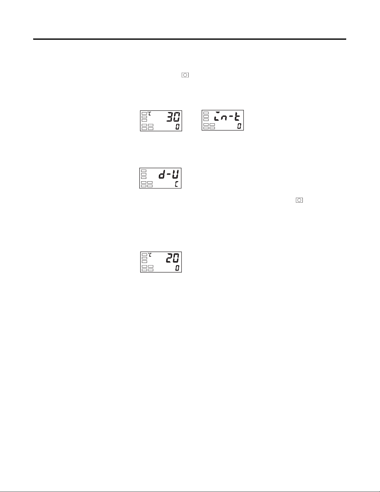
Example Operation Procedure — Select °C
1. Press the key for at least 3 seconds to move from the Operation
function group to the Initial Setting function group.
Figure 3.9
Operation function group
2. Select the Temperature Unit parameter by pressing the M key. Press the
U or D key to select either °C (c) or °F (f).
Figure 3.10
3. To return to the Operation function group press the key for at least
1 second.
Initial setting function group
Input type
Temperature unit
Configuring the SP
Figure 3.11
Operation function group
The Operation function group is displayed when the Bulletin 900-TC16 is
turned ON. The upper display (No. 1) shows the process value (PV), and the
lower display (No. 2) shows the set point (SV or SP).
Changing the SP
The set point cannot be changed when the Operation/Adjustment Protection
parameter is set to 3. For details, see p. 4-28, Using the Key Protect Function Group.
To change the set point, press the U or D key in the PV/SP parameter
(Operation function group), and configure the desired value. The new set
point is selected 2 seconds after you have specified the new value.
The Multi-SP parameter is used to switch between two or four pre-configured
set point values. See p. 4-16, Using the Event Input Feature for details.
Publication 900-UM001C-EN-E - January 2004
Example Operation Procedure
In this example, the set point will be changed from 0°C to 200°C.
Page 45

Configuration and Basic Operation 3-11
1. Normally, the PV/SP parameter is displayed. The set point is 0°C.
Figure 3.12
Operation level
2. Press the U or D key until the set point changes to 200°C.
Figure 3.13
Note: The newly configured value or parameter is loaded into controller
memory if you do not operate any key on the front panel for at least 2 seconds
or by pressing the or M key.
Selecting PID Control or ON/OFF Control
Overview
The Bulletin 900-TC16 supports two control methods, 2-PID control and
ON/OFF control. The control method is selected by the PID/ON/OFF
parameter in the Initial Setting function group. When this parameter is set to
pid, 2-PID control is set, and when set to onof, ON/OFF is set. Note: The
default is ON/OFF control.
2-PID Control
PID control parameters are set by AT (auto-tuning), ST (self-tuning), or
manual setup. For PID control, set the PID constants in the Proportional
Band (P), Integral Time (I), and Derivative Time (D) parameters. For more
details, see p. 3-18.
Publication 900-UM001C-EN-E - January 2004
Page 46
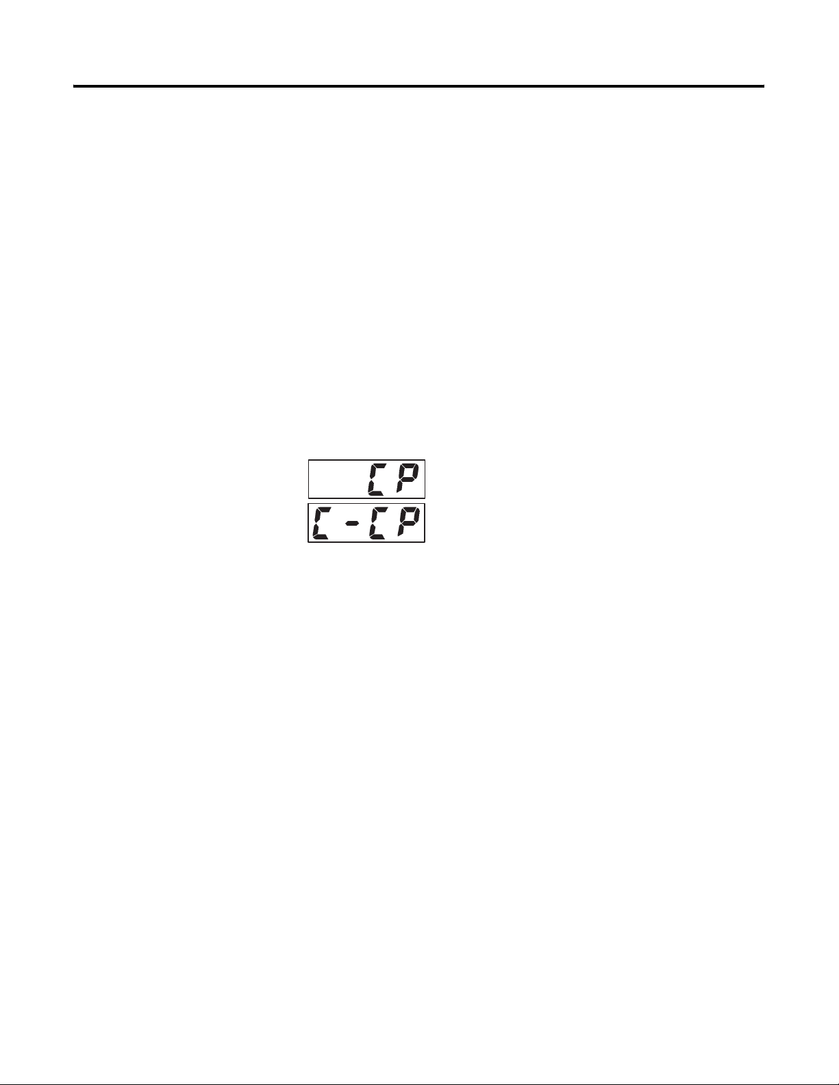
3-12 Configuration and Basic Operation
ON/OFF Control
In the ON/OFF control method, the control output (MV) is turned ON when
the process value is lower than the current set point, and the control output is
turned OFF when the process value is higher than the current set point. This
is known as reverse operation. Direct operation refers to control where the
manipulated variable is increased according to the increase in the process
value.
Configuring the Output Parameters
Control Period
The Control Period parameter is used in the PID control method and allows
you to adjust the minimum amount of time between ON cycles of the
ON/OFF output (MV).
Figure 3.14
Control
period
(OUT1)
Control
period
(OUT2)
A shorter period may provide better ON/OFF control performance.
However, we recommend setting the control period to 20 seconds or more for
electromechanical relay outputs. In the case of an electromechanical relay
output, doing this will increase its life expectancy. If necessary, readjust the
control period by trial operation to meet the needs of the application.
• Configure the control period value in the Control Period (OUT1) and
Control Period (OUT2) parameters (Initial Setting function group).
Note: The default is 20 seconds.
Publication 900-UM001C-EN-E - January 2004
• The Control Period (OUT2) parameter can only be used in heating and
cooling control method.
Note: The Control Period parameter allows what is typically called “time
proportioning” ON/OFF control to be done in the 2-PID method.
Page 47
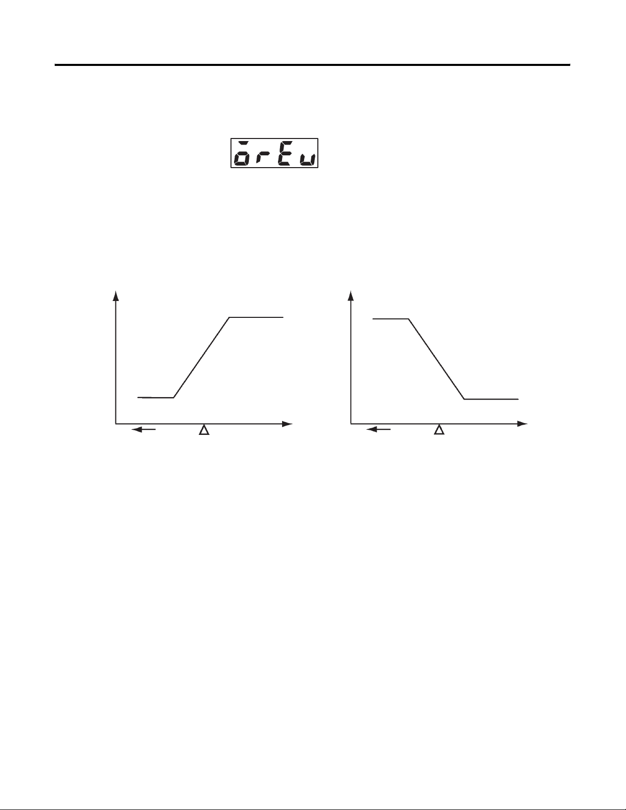
Manipulated variable (MV)
100%
Configuration and Basic Operation 3-13
Direct/Reverse Operation
Figure 3.15
Direct operation refers to control where the manipulated variable is increased
according to the increase in the process value (PV). Alternatively, reverse
operation refers to control where the manipulated variable (MV) is decreased
according to the increase in the process value (see Figure 3.16). Direct/reverse
operation can be used in ON/OFF or PID control.
Figure 3.16 Direct/Reverse Operation
Manipulated variable (MV)
100%
0%
Low temperature
Set value (SP)
Direct operation
For example, when the process value temperature is lower than the set point
(SP) temperature in a heating control system, the manipulated variable (OUT1)
increases (ON) by the difference between the PV and SP values.
Accordingly, this becomes reverse operation in a heating control system, or
alternatively, direct operation in a cooling control system.
Direct/reverse operation is set in the Direct/Reverse Operation parameter
(Initial Setting function group). Note: The Direct/Reverse Operation
parameter default is reverse operation.
Example Operation Procedure
In this example, the Input Type, Temperature Unit, Direct/Reverse Operation,
and Control Period (OUT1) parameters will be monitored.
High temperature
0%
Low temperature
High temperature
Set value (SP)
Reverse operation
Publication 900-UM001C-EN-E - January 2004
Page 48
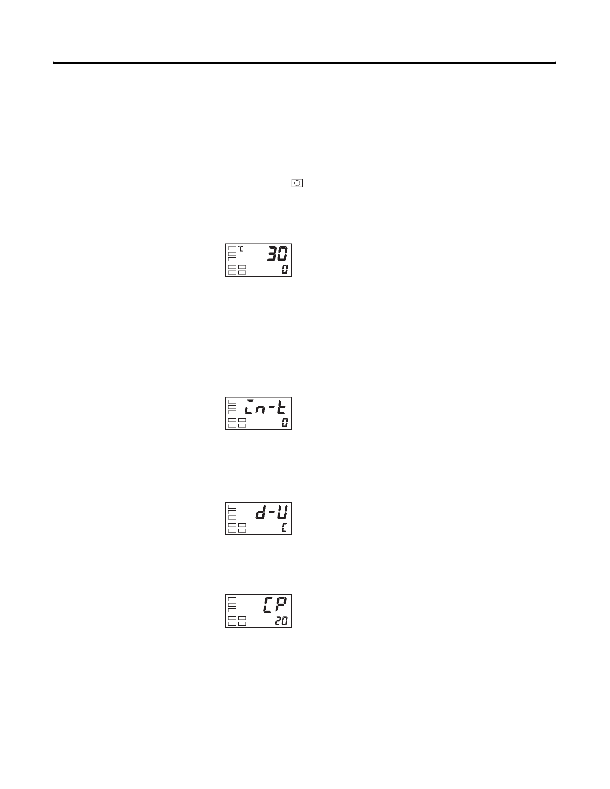
3-14 Configuration and Basic Operation
The parameter setup is as follows:
Input Type = 0: K thermocouple
Temperature Unit = c: °C
Direct/Reverse Operation = or-r: reverse operation
Control Period (OUT1) = 20 seconds
1. Press the key for at least 3 seconds to move from the Operation
function group to the Initial Setting function group.
Figure 3.17
Operation function group
2. The Input Type is displayed. When you are monitoring/configuring the
Input Type for the first time, 0: K type thermocouple is set as the
default. (0 is set if you have a platinum resistance
thermometer-compatible controller [see Table 1.A].) To select a
different sensor, press the U or D keys. This changes the Set Value
(see Table A.D, List of Input Types) to match the desired sensor input.
Figure 3.18
Initial Setting function group
Input type
3. Select the Temperature Unit parameter by pressing the M key. Note:
The default is c: °C. To configure f: °F, press either of the U or D
keys.
Figure 3.19
Temperature unit
4. Select the Control Period (OUT1) parameter by pressing the M key.
Note: The default is 20.
Figure 3.20
Control period
(OUT1)
Publication 900-UM001C-EN-E - January 2004
Page 49
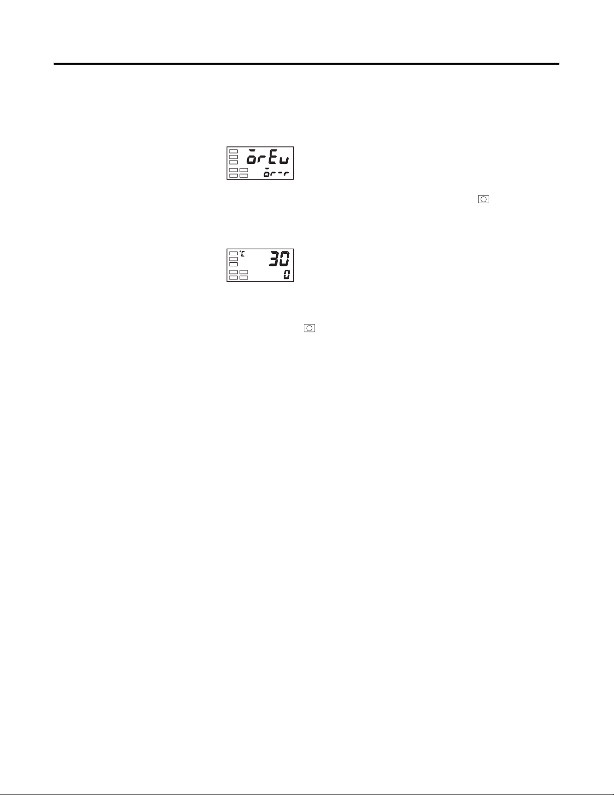
Configuration and Basic Operation 3-15
5. Select the Direct/Reverse Operation parameter by pressing the M key.
Note: The default is or-r: reverse operation. To select or-d: direct
operation, press either U or D keys.
Figure 3.21
Direct/reverse
operation
6. To return to the Operation function group press the key for at least
1 second.
Figure 3.22
Operation level
PV/SP
Note: The newly configured value or parameter is loaded into controller
memory if you do not operate any key on the front panel for at least 2 seconds
or by pressing the or M key.
Executing the ON/OFF Control Method
ON/OFF Overview
In the reverse operation ON/OFF control method, the control output (MV)
turns OFF when the controlled temperature (PV) reaches the user-defined set
point. When the control output (MV) turns OFF, the controlled temperature
begins to fall and the control output (MV) turns ON again. This operation is
repeated at a certain point. At this time, how much the temperature must fall
before the control output (MV) turns ON again is determined by the
Hysteresis (OUT1) parameter. Also, how much the manipulated variable must
be adjusted in response to the increase or decrease in the process value is
determined by the Direct/Reverse Operation parameter.
ON/OFF Control Parameters
Switching between the 2-PID control method and ON/OFF control method
is carried out by the PID/ON/OFF parameter (Initial Setting function group).
When this parameter is configured to pid, 2-PID control is selected, and
when configured to onof, ON/OFF control is selected. Note: The default is
onof.
Publication 900-UM001C-EN-E - January 2004
Page 50
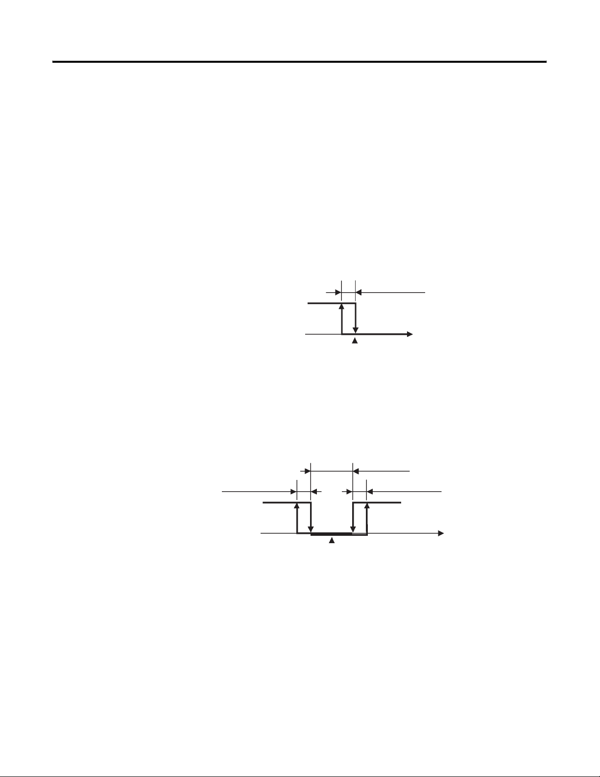
3-16 Configuration and Basic Operation
Hysteresis
In the ON/OFF control method hysteresis is used to provide
margin/differential for switching the control output ON when the controlled
temperature moves away from the required set point. The Hysteresis
parameter is used to provide stability to the output around the set point.
The hysteresis value for control output (OUT1) and control output (OUT2)
functions are configured in the Hysteresis (OUT1) and Hysteresis (OUT2)
parameter functions, respectively. In standard heating or cooling control, the
Hysteresis (OUT1) setting is used as the hysteresis setting (Adjustment
function group) regardless of the control mode, heating control, or cooling
control.
Figure 3.23
Reverse operation
ON
OFF PV
Hysteresis (OUT1)
Set point
3-Position Control
In the heating and cooling control method, a dead band (an area where both
control outputs are 0) can be configured for either the heating or cooling side
of the set point. This makes 3-position control possible.
Figure 3.24
Dead band
Hysteresis (OUT1)
ON
Heating
side
OFF
Set point
Hysteresis (OUT2)
Cooling
side
PV
Publication 900-UM001C-EN-E - January 2004
Page 51
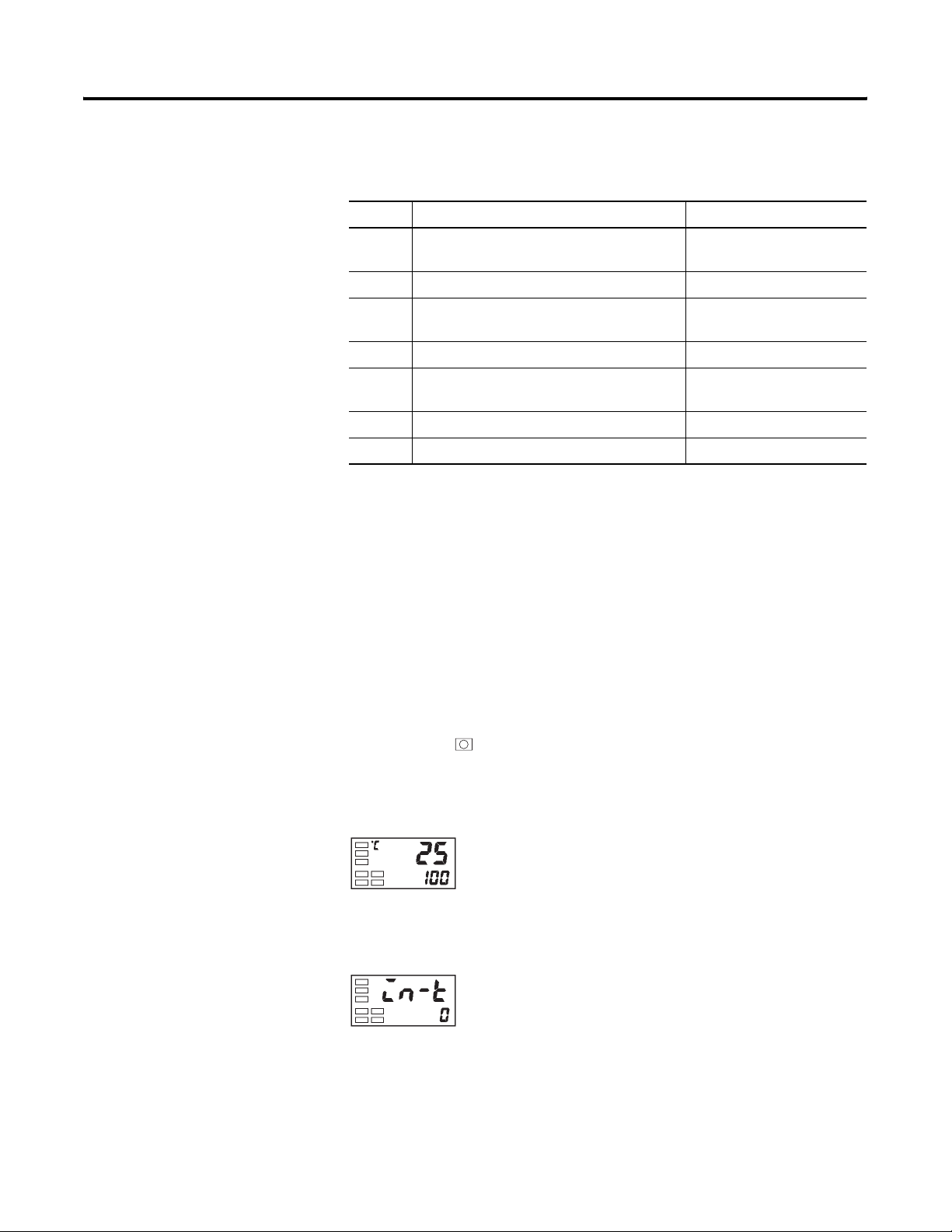
Configuration and Basic Operation 3-17
Table 3.C Control Parameters
Symbol Parameter Name: Function Group Description
s-hc Standard/Heating and Cooling: Initial Setting
function group
cntl PID/ON/OFF: Initial Setting function group For specifying control method
orev Direct/Reverse Operation: Initial Setting
function group
c-db Dead Band: Adjustment function group Heating and cooling control
c-sc Cooling Coefficient: Adjustment function
group
hys Hysteresis (OUT1): Adjustment function group ON/OFF control
chys Hysteresis (OUT2): Adjustment function group ON/OFF control
For specifying control method
For specifying control method
Heating and cooling control
ON/OFF Control Setup
To execute ON/OFF control, configure the PID/ON/OFF and Hysteresis
parameters.
Example Operation Procedure — Configuring the PID/ON/OFF Parameter
In this example, first check that the PID/ON/OFF control method parameter
is set to onof in the Initial Setting function group.
1. Press the key for at least 3 seconds to move from the Operation
function group to the Initial Setting function group.
Figure 3.25
Operation function group
PV
2. Display the Input Type parameter in the Initial Setting function group.
Figure 3.26
Initial Setting function group
Input type
Publication 900-UM001C-EN-E - January 2004
Page 52
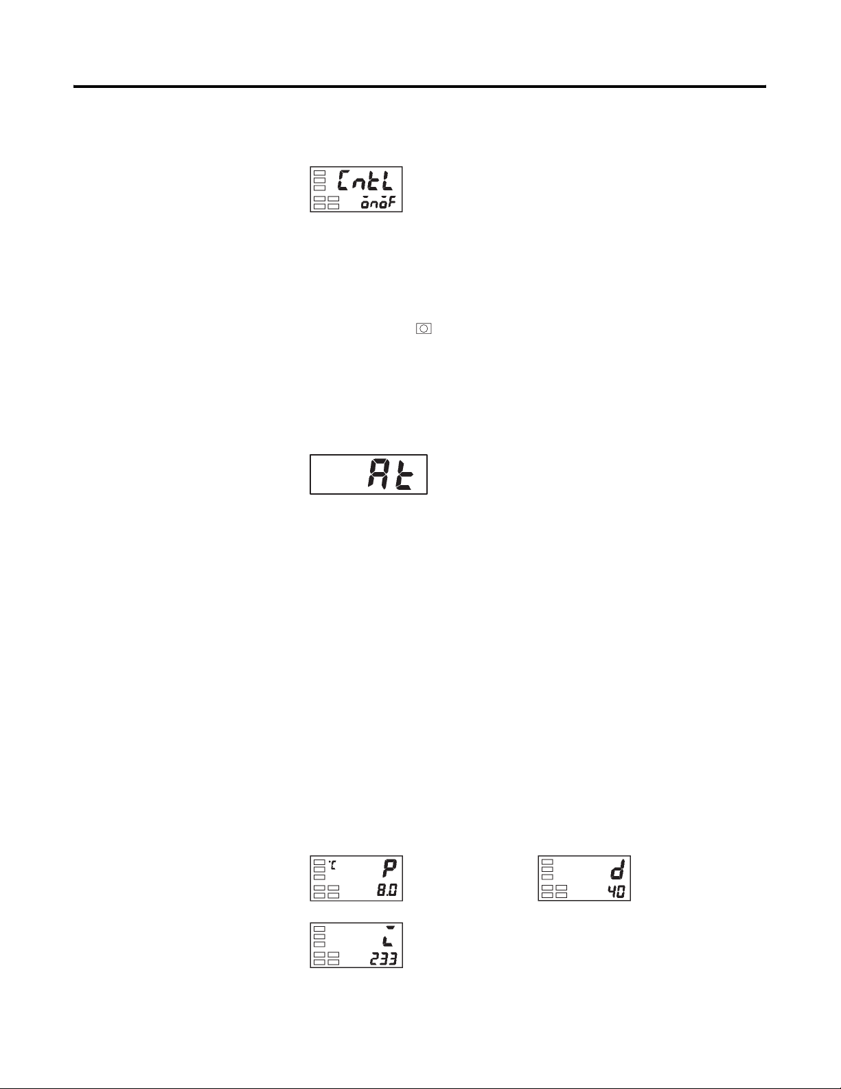
3-18 Configuration and Basic Operation
3. Select the PID/ON/OFF parameter by pressing the M key.
Figure 3.27
PID / ON/OFF
4. Check that the configured control method parameter is onof. Note:
The default is onof.
Note: The newly configured value or parameter is loaded into controller
memory if you do not operate any key on the front panel for at least 2 seconds
or by pressing the or M key.
Determining PID Constants (AT, ST, Manual Setup)
AT (Auto-Tuning)
Figure 3.28
Overview
When you configure the controller to execute auto-tuning, the optimum PID
constants for the current set point during program execution are automatically
configured by the controller forcibly changing the manipulated variable (MV)
to calculate the characteristics (called the limit cycle method) of the control
target.
To have the controller execute AT (auto-tuning), specify on: AT execute, and
to cancel AT (auto-tuning), specify off: AT cancel.
Note: AT (auto-tuning) cannot be executed during ON/OFF control.
The result of a controller AT (auto-tuning) cycle can be viewed/monitored
from the Proportional Band (P), Integral Time (I), and Derivative Time (D)
parameters located in the Adjustment function group.
Publication 900-UM001C-EN-E - January 2004
Figure 3.29
Adjustment function group
Proportional band
Integral time
Derivative time
Page 53
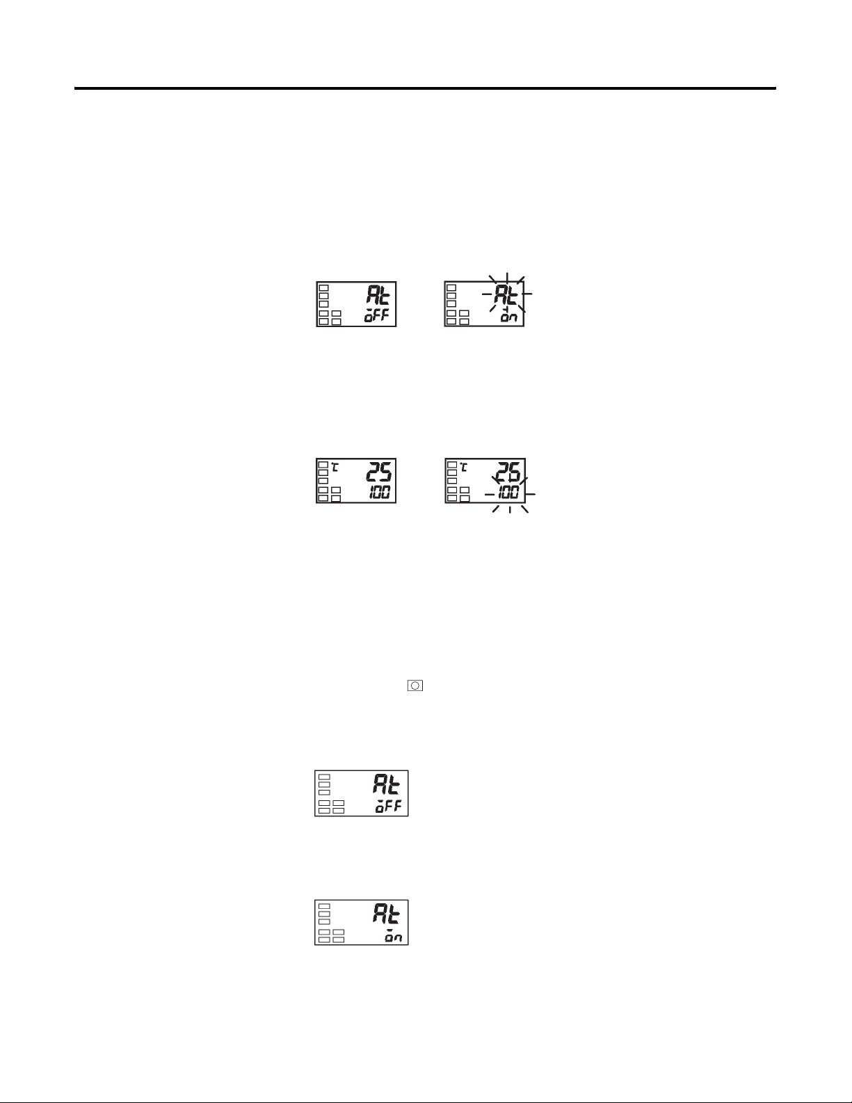
Configuration and Basic Operation 3-19
/
AT Description and Display Consideration
AT (auto-tuning) is started when you configure the AT Execute/Cancel
parameter to ON. During execution of AT, the No. 1 display for the AT
Execute/Cancel parameter blinks (see Figure 3.30). When AT ends, the AT
Execute/Cancel parameter turns OFF, and the No. 1 display stops blinking.
Figure 3.30
During AT execution
No. 1 display
If you move to the Operation function group during AT execution, the No. 2
display blinks to indicate that AT is being executed.
Figure 3.31
During AT execution
No. 2 display
Note: Only the Communications Writing, RUN/STOP, and AT
Execution/Cancel parameters can be changed during AT execution. Other
parameters cannot be changed.
Example Operation Procedure — Execute Auto-Tuning (AT)
1. Press the key for less than 1 second to move from the Operation
function group to the Adjustment function group.
Figure 3.32
Adjustment function group
AT execute
cancel
2. Press the U key to start execution of AT. on is displayed during AT
execution.
Figure 3.33
Publication 900-UM001C-EN-E - January 2004
Page 54
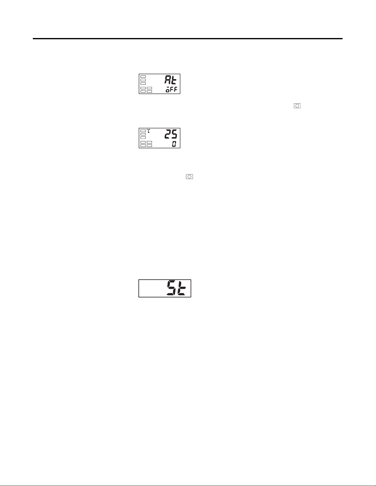
3-20 Configuration and Basic Operation
3. off is displayed when AT ends.
Figure 3.34
4. To return to the Operation function group, press the key.
Figure 3.35
Operation function group
PV
Note: The newly configured value or parameter is loaded into controller
memory if you do not operate any key on the front panel for at least 2 seconds
or by pressing the or M key.
Note: When control characteristics are already known either from experience
or from a previous AT cycle, the PID parameters can be configured directly
from the keypad to adjust control. PID values are configured in the
Proportional Band (P), Integral Time (I), and Derivative Time (D) parameters
in the Adjustment function group.
ST (Self-Tuning)
Figure 3.36
In the ST (self-tuning) function the controller executes its tuning process from
the start of program execution to calculate the PID constants matched to the
actual control target.
Once the self-tuning PID constants have been calculated, and as long as the
set point remains unchanged, ST is not executed during the next control
operation/cycle.
Example Operation Procedure — Execute Self-Tuning (ST)
ST (self-tuning) is executed when the ST parameter is set to ON in the Initial
Setting function group.
When the ST function is in operation, make sure to turn the power supply of
the load connected to the control output (MV) ON simultaneously with or
before starting operation of the Bulletin 900-TC16.
Publication 900-UM001C-EN-E - January 2004
Page 55
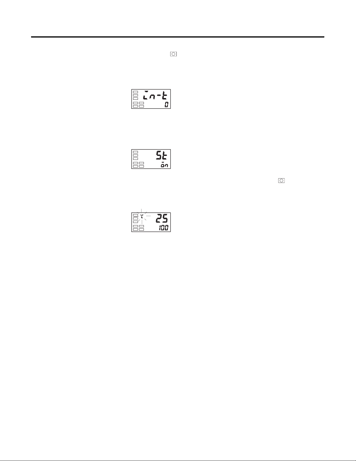
Configuration and Basic Operation 3-21
1. Press the key for at least 3 seconds to move from the Operation
function group to the Initial Setting function group.
Figure 3.37
Initial Setting function group
Input type
2. Select the ST parameter by pressing the M key.
3. Press the U key to select on. Note: The default is on.
Figure 3.38
ST
4. To return to the Operation function group, press the key. The
temperature display blinks during self-tuning (ST) execution and stops
when it is complete.
Figure 3.39
ST
Note: When control characteristics are already known either from experience
or from a previous AT cycle, the PID parameters can be configured directly
from the keypad to adjust control. PID values are configured in the
Proportional Band (P), Integral Time (I), and Derivative Time (D) parameters
in the Adjustment function group.
Conditions that Start Self-Tuning (ST)
Self-tuning by Step Response Tuning (SRT) is started when either of the two
following major conditions are met:
• Program execution is started.
• The set point is changed.
Publication 900-UM001C-EN-E - January 2004
Page 56

3-22 Configuration and Basic Operation
The following table provides some additional details.
Table 3.D
At Start of Program Execution
(Self-Tuning ON)
1. The set point at the start of program
execution differs from the set point (see
Note 1) when the previous SRT cycle
was executed.
2. The difference between the controlled
temperature at the start of program
execution is larger than the current
proportional band (1.27+4°C) or the ST
stable range, whichever is larger.
3. The controlled temperature at the start
of program execution is smaller than the
set point during reverse operation, and is
larger than the set point during direct
operation.
4. No reset from input error
When Set Point is Changed
(Self-Tuning ON)
1. The new set point differs from the set
point (see Note 1) used when the
previous SRT cycle was executed.
2. The set point change width is larger than
the current proportional band 1.27+4°C
or the ST stable range, whichever is
larger.
3. During reverse operation, the new set
point is larger than the set point before
the change; and during direct operation,
the new set point is smaller than the set
point before the change.
4. The temperature is in a stable state (see
Note 2). An equilibrium state (see
Note 3) is acceptable when the output is
0% when the power is turned ON.
Note 1: The previous SRT-implemented set point is called the set point
obtained by calculating the PID constant by the previous SRT.
Note 2: In this state, the measurement point is within the ST stable range.
Note 3: In this state, the change width of the PV every 60 seconds is at the ST
stable range or less.
New PID constants are not calculated by self-tuning (ST) for the currently
configured set point in the following instances:
• When the PID constants have been changed manually with ST set to
ON.
• When auto-tuning (AT) has been executed.
Self-Tuning (ST) Stable Range
The self-tuning (ST) stable range is a mechanism which allows you to
determine the condition under which the ST function occurs.
In this example, the ST stable range will be configured to 20°C.
Example Operation Procedure
1. Select the ST Stable Range parameter by pressing the M key in the
Advanced Setting function group. To move to this function group, see
p. 4-26, To Move to the Advanced Setting Function Group.
Publication 900-UM001C-EN-E - January 2004
Page 57
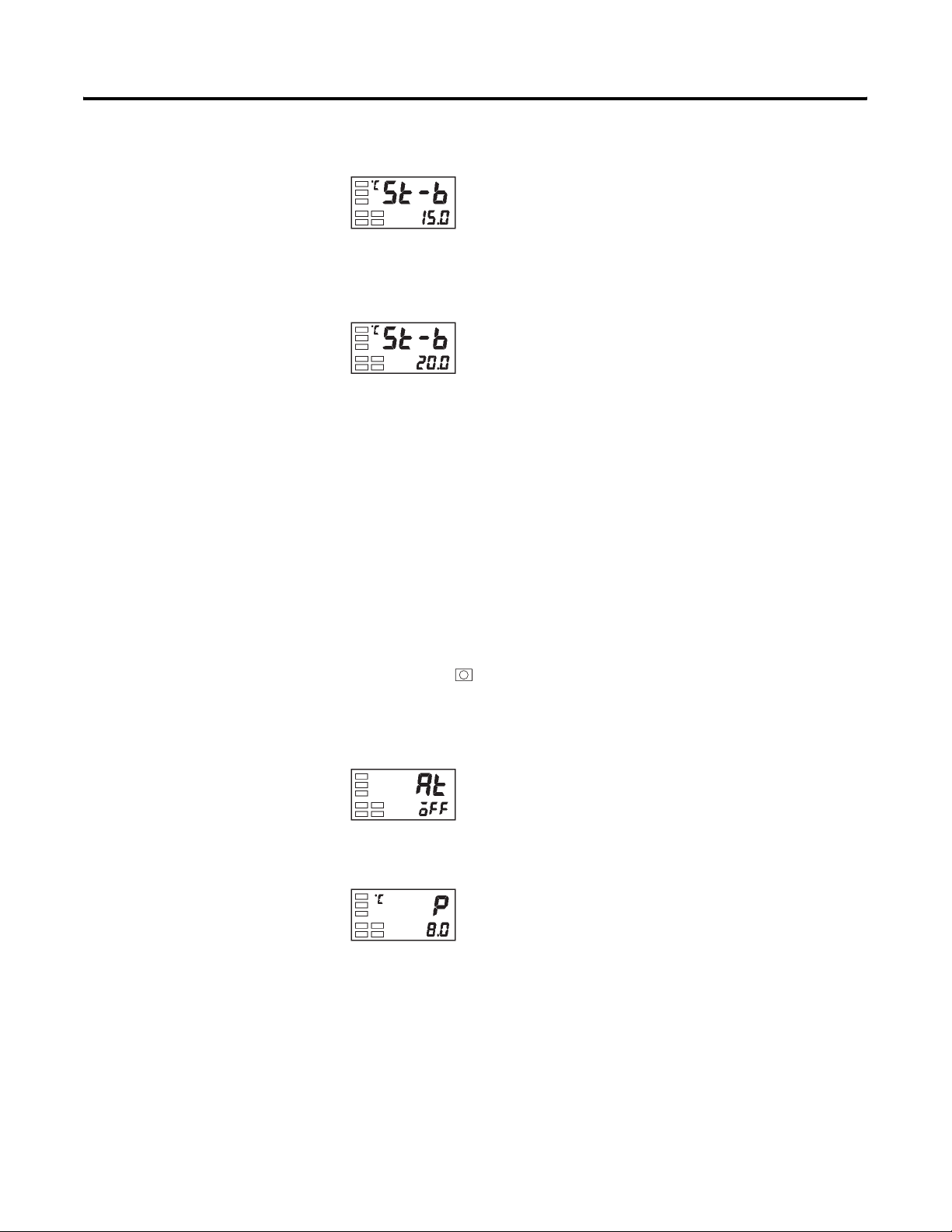
Configuration and Basic Operation 3-23
/
Figure 3.40
Advanced Setting function group
ST stable range
2. Configure to 20°C (deviation) using the U key. Note: The default is
15°C.
Figure 3.41
Manual PID Setup
The individual PID values can be manually set in the Proportional Band,
Integral Time, and Derivative Time parameters in the Adjustment function
group.
Example Operation Procedure
In this example, the Proportional Band parameter will be configured to 10.0,
the Integral Time parameter to 250, and the Derivative Time parameter to 45.
1. Press the key to move from the Operation function group to the
Adjustment function group.
Figure 3.42
Adjustment function group
AT execute
cancel
2. Select Proportional Band by pressing the M key.
Figure 3.43
Proportional
band
Publication 900-UM001C-EN-E - January 2004
Page 58
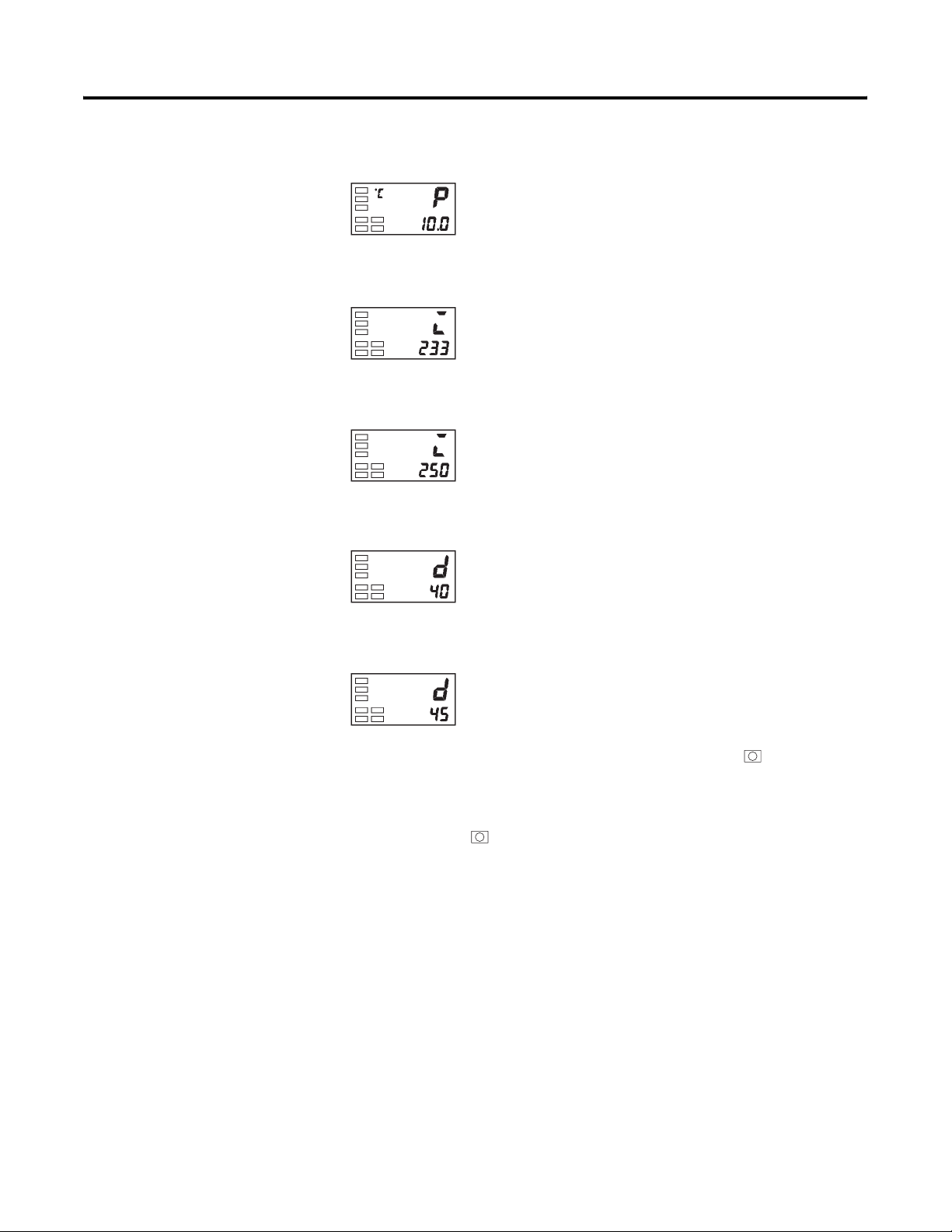
3-24 Configuration and Basic Operation
3. Press the U or D key to set the Proportional Band parameter to 10.0.
Figure 3.44
4. Select Integral Time by pressing the M key.
Figure 3.45
Integrated
time
5. Press the U or D key to set the Integral Time parameter to 250.
Figure 3.46
6. Select Derivative Time by pressing the M key.
Figure 3.47
Derivative
time
7. Press the U or D key to set the parameter to 45.
Figure 3.48
8. To return to the Operation function group, press the key.
Note: The newly configured value or parameter is loaded into controller
memory if you do not operate any key on the front panel for at least 2 seconds
or by pressing the or M key.
Note: When PID values I (integral time) and D (derivative time) are set to
zero (0), control is executed according to proportional operation and the
default set point becomes the center value of the proportional band. In this
case a related parameter is Manual Reset Value (Adjustment function group).
Publication 900-UM001C-EN-E - January 2004
Page 59
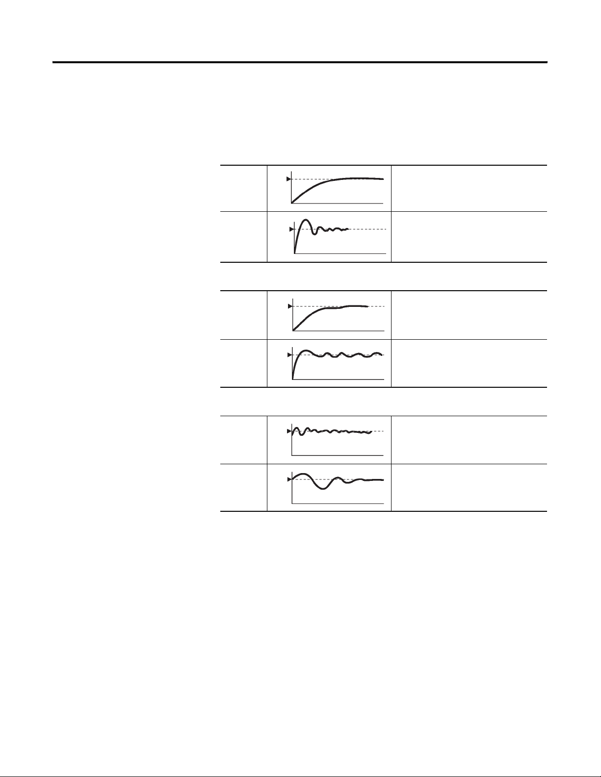
Configuration and Basic Operation 3-25
The following diagrams provide a basic explanation of how adjusting the P, I,
and D parameter values impact system operation.
Table 3.E When P (Proportional Band) is Adjusted
When P is
increased
When P is
decreased
Set
Point
Set
Point
PV
PV
The curve rises gradually, and a long
stable time is achieved, preventing
overshoot.
Overshoot and hunting occur, however
the set point is quickly reached after
which the curve stabilizes.
Table 3.F When I (Integral Time) is Adjusted
When I is
increased
When I is
decreased
Set
Point
Set
Point
PV
PV
It takes a long time for the process value
to reach the set point. It takes time to
achieve a stable state, however there is
little overshoot/undershoot and hunting.
Overshoot/undershoot and hunting occur,
and the curve rises quickly.
Table 3.G When D (Derivative Time) is Adjusted
When D is
increased
Set
Point
PV
Overshoot/undershoot and stable time
are reduced, however, fine hunting occurs
on changes in the curve it self.
Alarm Outputs
When D is
decreased
Set
Point
PV
Overshoot/undershoot increase, and it
takes time for the process value to reach
the set point.
Alarm Types
The Bulletin 900-TC16 supports two alarm outputs.
Alarm output conditions are determined by the combination of the selected
Alarm Type, Alarm Hysteresis, and Set Point parameters.
Alarm types are set independently for each alarm output using the Alarm 1
and Alarm 2 Type parameters (Initial Setting function group). Note: The
default Set Value is 2: upper-limit (deviation).
Publication 900-UM001C-EN-E - January 2004
Page 60
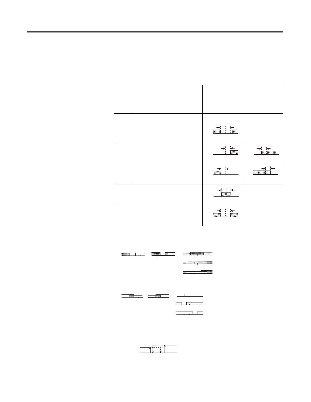
3-26 Configuration and Basic Operation
Configure the Alarm Type and Alarm Output Operation based on pre-defined
conditions using the Set Value number. Table 3.H describes the Alarm Type,
Alarm Value, Upper-Limit Alarm, and Lower-Limit Alarm parameters.
Table 3.H
Set
Value
Alarm Type Alarm Output Operation
When Alarm
Value X is
Positive
When Alarm
Value X is
Negative
0 Alarm function OFF Output OFF
1 ➊ Upper- and lower-limit (deviation
range)
2 ➌ Upper-limit (deviation)
3 Lower-limit (deviation)
4 ➊ Upper- and lower-limit range
(deviation range)
5 ➊➏ Upper- and lower-limit alarm with
standby sequence (deviation range)
ON
OFF
ON
OFF
ON
OFF
ON
OFF
ON
OFF
LH
SP
X
SP
X
SP
LH
SP
LH
SP
ON
OFF
ON
OFF
➊ With set values 1, 4, and 5, the upper- and lower-limit values can be configured independently for each alarm
point, and are expressed as L and H.
➋ Set value: 1 upper- and lower-limit alarm
Case 1 Case 2 Case 3 (Normally ON)
LHSP LHSP
H < 0, L > 0
|H| < |L|
H > 0, L < 0
|H| > |L|
LHSP
LHSP
LHSP
H < 0, L < 0
H < 0, L > 0
>
|H| |L|
=
H > 0, L < 0
<
|H| |L|
=
➌ Default
➍ Set value: 4 upper- and lower-limit range
Case 1 Case 2 Case 3 (Normally OFF)
LHSP LHSP
H < 0, L > 0
|H| < |L|
H > 0, L < 0
|H| > |L|
LHSP
LHSP
LHSP
H < 0, L < 0
H < 0, L > 0
>
|H| |L|
=
H > 0, L < 0
<
|H| |L|
=
➎ Set value: 5 upper- and lower-limit alarm with standby sequence
* For the above upper- and lower-limit alarm
- In cases 1 and 2, the alarm is normally OFF if upper- and lower-limit values of hysteresis overlap.
- In case 3, the alarm is normally OFF.
Cases 1 and 2 example:
➋
X
SP
X
SP
➍
➎
Publication 900-UM001C-EN-E - January 2004
➏ Set value: 5 upper- and lower-limit alarm with standby sequence
The alarm is normally OFF if upper- and lower-limit values of hysteresis overlap.
Page 61
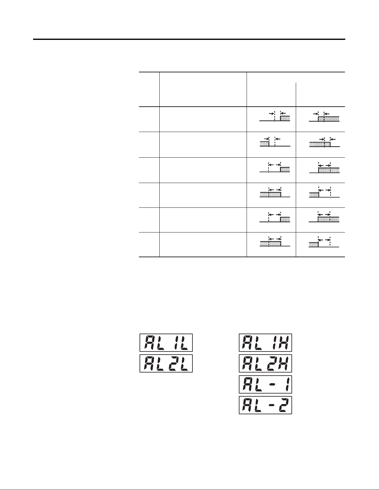
Table 3.H (Continued)
Configuration and Basic Operation 3-27
Set
Alarm Type Alarm Output Operation
Value
6 Upper-limit alarm with standby
sequence (deviation)
7 Lower-limit alarm with standby
sequence (deviation)
8 Upper-limit (absolute-value)
9 Lower-limit (absolute-value)
10 Upper-limit with standby sequence
(absolute-value)
11 Lower-limit with standby sequence
(absolute-value)
When Alarm
Value X is
Positive
ON
OFF
ON
OFF
ON
OFF
ON
OFF
ON
OFF
ON
OFF
X
SP
X
SP
X
0
X
0
X
0
X
0
When Alarm
Value X is
Negative
ON
OFF
ON
OFF
ON
OFF
ON
OFF
ON
OFF
ON
OFF
X
SP
SP
X
X
X
X
X
0
0
0
0
Alarm values are indicated by X in Table 3.H. When the upper and lower limit
values are configured independently, H is displayed for the upper limit value,
and L is displayed for lower limit value.
Alarm Value
Figure 3.49
Lower-limit
alarm value
To set the Upper- and Lower-Limit Alarm parameters, set the upper and lower
limits in each of the Alarm 1 Upper Limit, Alarm 2 Upper Limit, Alarm 1
Lower Limit, and Alarm 2 Lower Limit parameters (available in the Operation
function group).
Upper-limit
alarm value
Alarm value
Publication 900-UM001C-EN-E - January 2004
Page 62
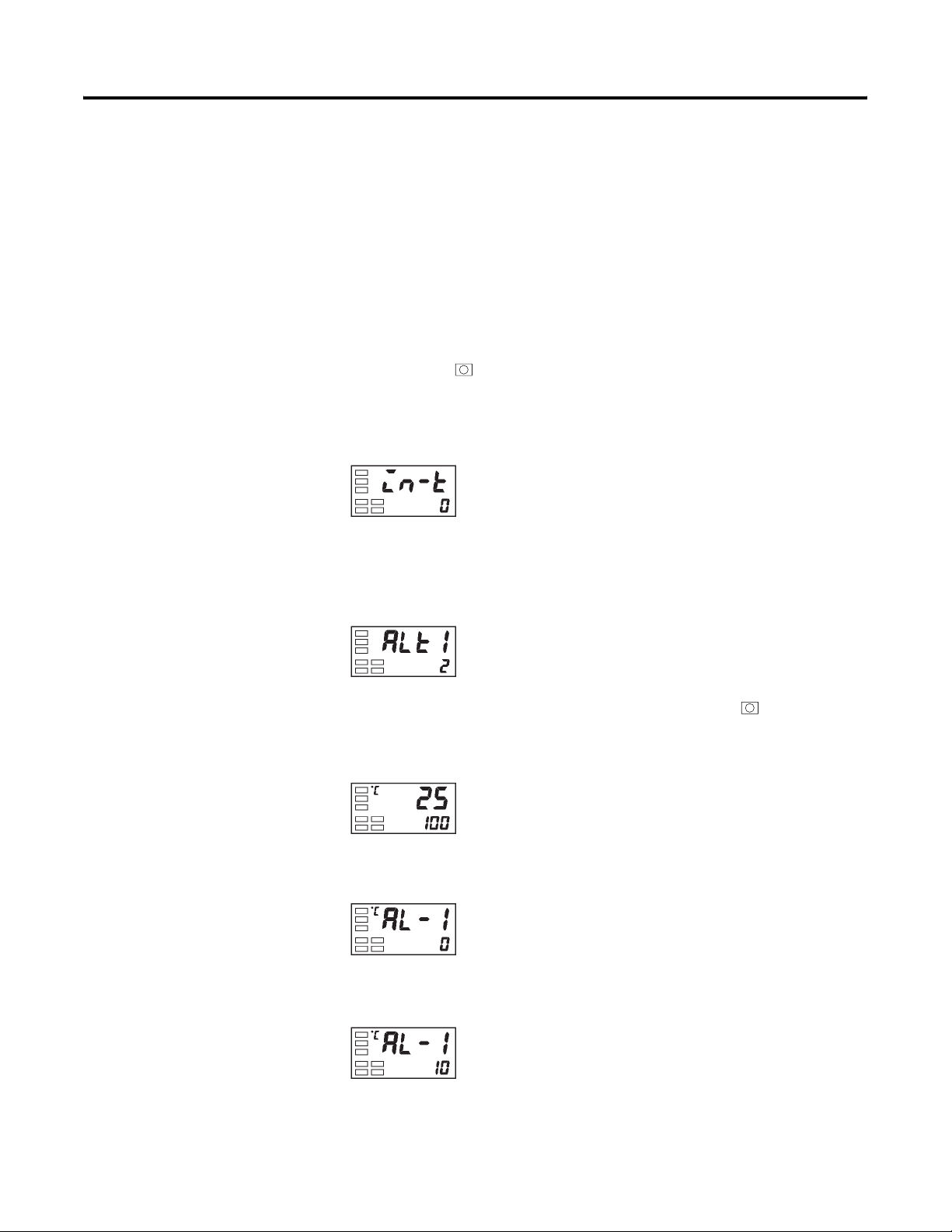
3-28 Configuration and Basic Operation
Example Operation Procedure
In this example, alarm 1 will be set to the upper-limit alarm. The following
shows related parameters and setups. In this example, the alarm output is
active when the set point is exceeded by 10°C. (The temperature unit in this
example is °C.)
Parameters to configure:
Alarm 1 Type = 2: upper-limit alarm (deviation)
Alarm Value 1 = 10 (10° greater than SP)
1. Press the key for at least 3 seconds to move from the Operation
function group to the Initial Setting function group.
Figure 3.50
Initial Setting function group
Input type
2. Select the Alarm 1 Type parameter by pressing the M key. Check that
the Alarm Type parameter is set to 2. Note: The default is upper-limit
alarm.
Figure 3.51
Alarm 1 type
3. To return to the Operation function group press the key for at least
1 second.
Figure 3.52
Operation function group
PV/SP
4. Select Alarm Value 1 by pressing M.
Figure 3.53
Alarm value 1
5. Press the U key to set the parameter to 10.
Figure 3.54
Publication 900-UM001C-EN-E - January 2004
Page 63
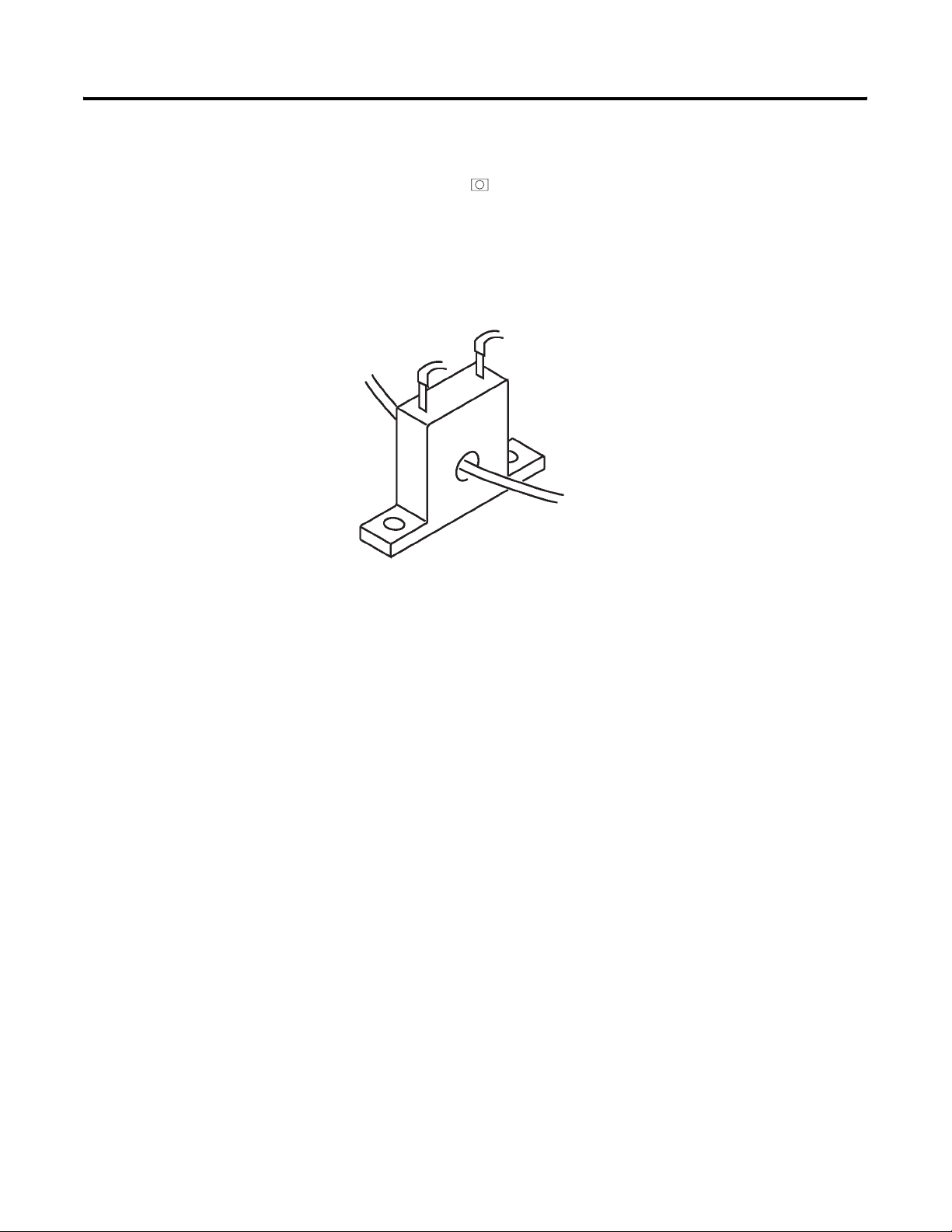
Configuration and Basic Operation 3-29
Note: The newly configured value or parameter is loaded into controller
memory if you do not operate any key on the front panel for at least 2 seconds
or by pressing the or M key.
Heater Burnout Alarm (HBA)
HBA Detection
Figure 3.55
To CT terminal
Heater lead
Heater burnout detection works as follows.
1. You must connect the current transformer (CT) to terminals 14 and 15,
and insert the heater lead through the CT hole. For specifications,
models, and external dimensions of current transformers that can be
used on this controller, see p. A-3, Current Transformer (CT).
2. When current flows through the heater lead, the current transformer
generates an AC current proportional to the heater current value. The
ON/OFF output type Bulletin 900-TC16 measures this AC current to
calculate the current flowing to the heater.
3. If the heater is burned out, the current measured at the current
transformer decreases. This value is compared with the value configured
as the heater burnout value, and the output becomes active as the heater
burnout alarm.
For the controller to measure the heater current from the CT, configure the
heater burnout set value in the Heater Burnout Detection parameter from the
Adjustment function group. To monitor the current value of the current
transformer, use the Heater Current Monitor parameter.
When you are not using the HBA function, set the Heater Burnout Used
parameter from the Advanced Setting function group to OFF.
Publication 900-UM001C-EN-E - January 2004
Page 64

3-30 Configuration and Basic Operation
HBA Operating Conditions
1. The HBA function can be used when the option unit (Cat.
No. 900-TC16COM or 900-TC16EIM) is mounted in an ON/OFF
output type Bulletin 900-TC16. Make sure to connect the CT to the
Bulletin 900-TC16, and pass the heater lead through the CT hole.
2. Turn the heater power ON at the same time as or before turning power
ON to the ON/OFF output type Bulletin 900-TC16. If the heater
power is turned ON after turning power to the Bulletin 900-TC16 ON,
the heater burnout alarm will activate.
Notes:
• Control is continued even if the heater burnout alarm is active. That is,
the ON/OFF output type Bulletin 900-TC16 attempts to control the
heater on which the heater burnout alarm has not occurred.
• For the heater burnout alarm to activate, the alarm condition must exist
for 190 ms or more.
• The measured current value may sometimes differ slightly from the
actual current flowing to the heater. Check the current value in an actual
operating state in the Heater Current Monitor parameter.
• If there is little difference between the current in a normal state and the
current in the burnout state, detection may become unstable. On a
heater of current 10.0 A or less, maintain a difference of 1.0 A or more.
On a heater of current 10.0 A or more, maintain a difference of 2.5 A or
more.
• The HBA function cannot be used when the heater is controlled by an
analog output system. Also, 3-phase heaters cannot be used.
HBA Setup
To activate the heater burnout alarm, set the HBA Used parameter from the
Advanced Setting function group to ON and configure the heater burnout
activation/trip value in the Heater Burnout Detection parameter (Adjustment
function group).
Publication 900-UM001C-EN-E - January 2004
Example Operation Procedure
In this example, configure the Heater Burnout Detection parameter to 2.5.
Page 65
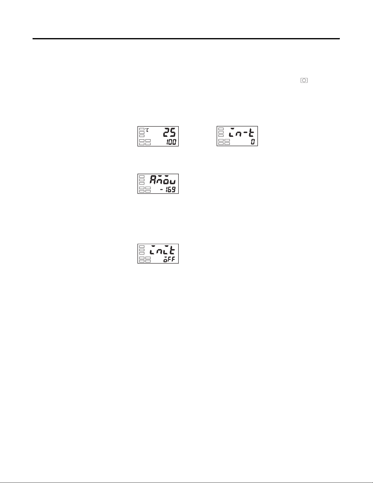
Configuration and Basic Operation 3-31
The default of the Heater Burnout Alarm Used (HBA) parameter is already
ON, so configure the Heater Burnout Detection value parameter.
1. Move to the Advanced Setting function group. Press the key for at
least 3 seconds to move from the Operation function group to the
Initial Setting function group.
Figure 3.56
Operation function group
PV/SP
Initial Setting function group
Input type
2. Then move to Advanced Setting function group by pressing the M key.
Figure 3.57
Move to advanced
Setting function group
3. Press the D key to enter the password (–169), and move from the Initial
Setting function group to the Advanced Setting function group. The top
parameter in the Advanced Setting function group is displayed.
Figure 3.58
Advanced Setting function group
Publication 900-UM001C-EN-E - January 2004
Page 66
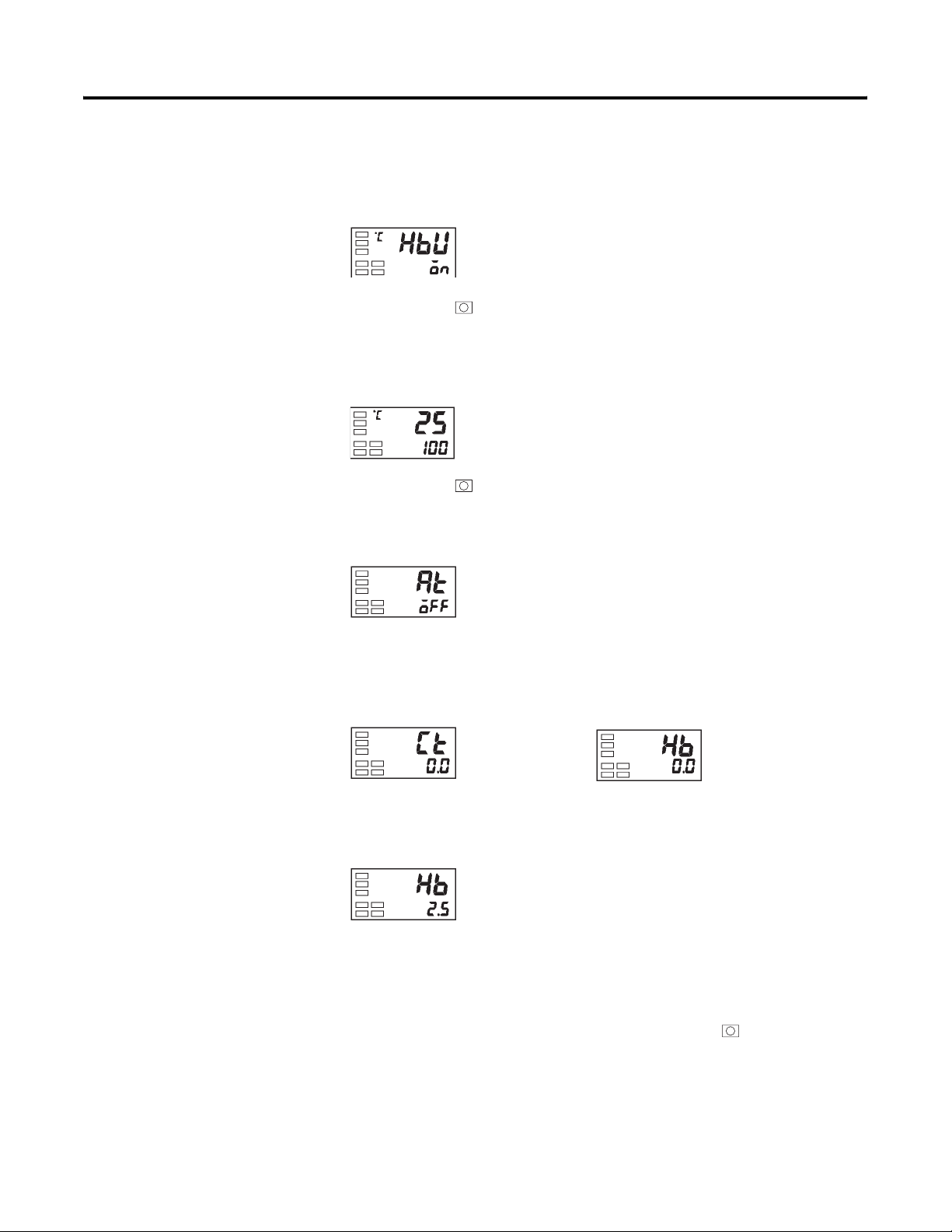
3-32 Configuration and Basic Operation
4. Select the HBA Used parameter by pressing the M key. Make sure that
this parameter is set to ON (default). Next, set the Heater Current Value
Monitor parameter.
Figure 3.59
HBA used
5. Press the key for at least 1 second to move from the Advanced
Setting function group to the Initial Setting function group and then to
the Operation function group.
Figure 3.60
Operation function group
PV/SP
6. Press the key for less than 1 second to move from the Operation
function group to the Adjustment function group.
Figure 3.61
Adjustment function group
AT execute/
cancel
7. Select the Heater Current Value Monitor parameter by pressing the M
key. Check the current value. Next, set the Heater Burnout Detection
value parameter.
Figure 3.62
Heater current
value monitor
Heater burnout
detection value
8. Select the Heater Burnout Detection value parameter by pressing the M
key.
Figure 3.63
9. Configure the current value as a reference value. Adjust this value so
that there is a large difference between the current flowing to the heater
lead when heater operation is normal and the current flowing when a
heater burnout occurs. For example, configure the value to 2.5. To
return to the Operation function group, press the key for less than
1 second.
Publication 900-UM001C-EN-E - January 2004
Page 67

Configuration and Basic Operation 3-33
How to Calculate Heater Current Detection Values
• Calculate the heater current value to be configured by the following
equation
:
Calculated value
heater current value at normal operation heater current value at burnout condition+( )
----------------------- ----------------------------- --------------------------------- ---------------------------- ----------------------------- --------------------------------- -------------------------=
2
• To calculate the value of the heater burnout when two or more heaters
are connected through the CT, use the current value of the smallest
heater connected, or the current value when one of the heaters burns
out if all the heaters have the same current value.
• Make sure that the following conditions are satisfied:
– Heater current of 10.0 A or less:
Current value at normal operation – current value at heater
burnout ≥ 1 A
(When the resultant current is less than 1 A, detection is unstable.)
– Heater current of 10.0 A or more:
Current value at normal operation – current value at heater
burnout ≥ 2.5 A
(When the resultant current is less than 2.5 A, detection is unstable.)
• The allowable heater burnout configuration range is 0.1…49.9 A.
Heater burnout is not detectable when the configured value is 0.0 or
50.0. When the configured value is 0.0, the heater burnout alarm is
always OFF, and if the configured value is 50.0, the heater burnout
alarm is always ON.
• Configure the total current value at normal heater operation to 50 A or
less. When configured to 55.0 A, ffff is displayed in the Heater
Current Monitor parameter.
Publication 900-UM001C-EN-E - January 2004
Page 68
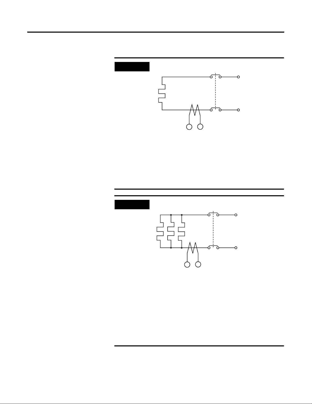
3-34 Configuration and Basic Operation
EXAMPLE
EXAMPLE
When using a 200V AC, 1 kW heater:
Heater
1KW
900-TC16 14 15
Current during normal operation
Control output
CT
AC200V
1000
----------- 5 A <10 A()==
200
Current at heater burnout 0 A=
Set value
Current at normal operation
Current at heater burnout
50+
------------ 2.5 A==
2
–(
) 50–()5 A ( 1 A)≥==
When using three 200V AC, 1 kW heaters:
Heater
Control output
1KWx3
CT
900-TC16 14 15
Current during normal operation
1000
-----------
200
3× 15 A ( 10 A)≥
=
Current at burnout of one heater
Set value
15 10+
----------------- 12.5 A==
2
Current at normal operation
Current at heater burnout
) 15 10–()5 A ( 2.5 A)≥==
AC200V
–(
=
1000
-----------
200
2× 10 A==
Publication 900-UM001C-EN-E - January 2004
Page 69

Configuration and Basic Operation 3-35
Table 3.I Parameters
Symbol Parameter: Function Group Description
System Setup/Operational Considerations
ct Heater Current Value Monitor:
Adjustment function group
hb Heater Burnout Detection:
Adjustment function group
hbh Heater Burnout Hysteresis:
Advanced Setting function group
hbl Heater Burnout Latch:
Advanced Setting function group
To monitor heater current value
For HBA configuration detection
For HBA configuration detection
For HBA configuration detection
• Allow at least a 30 minute warm-up period for the system to fully
stabilize.
• When self-tuning is used, turn the temperature controller and load (e.g.,
heater) power ON simultaneously or turn the load power ON before
the temperature controller. If the load is turned ON before the
temperature controller, correct self-tuning and optimum control are no
longer possible.
When operation is started after system warm-up, turn the power to the
system OFF once after warm-up is completed, and then turn the
temperature controller and load power ON simultaneously. (Instead of
turning the temperature controller power ON again, moving from the
STOP to the RUN mode also is possible.)
• The temperature controller may be subject to the influence of radio
interference if used near a radio, TV, or wireless equipment. For
additional information, see Appendix A.
Publication 900-UM001C-EN-E - January 2004
Page 70

3-36 Configuration and Basic Operation
Notes:
Publication 900-UM001C-EN-E - January 2004
Page 71
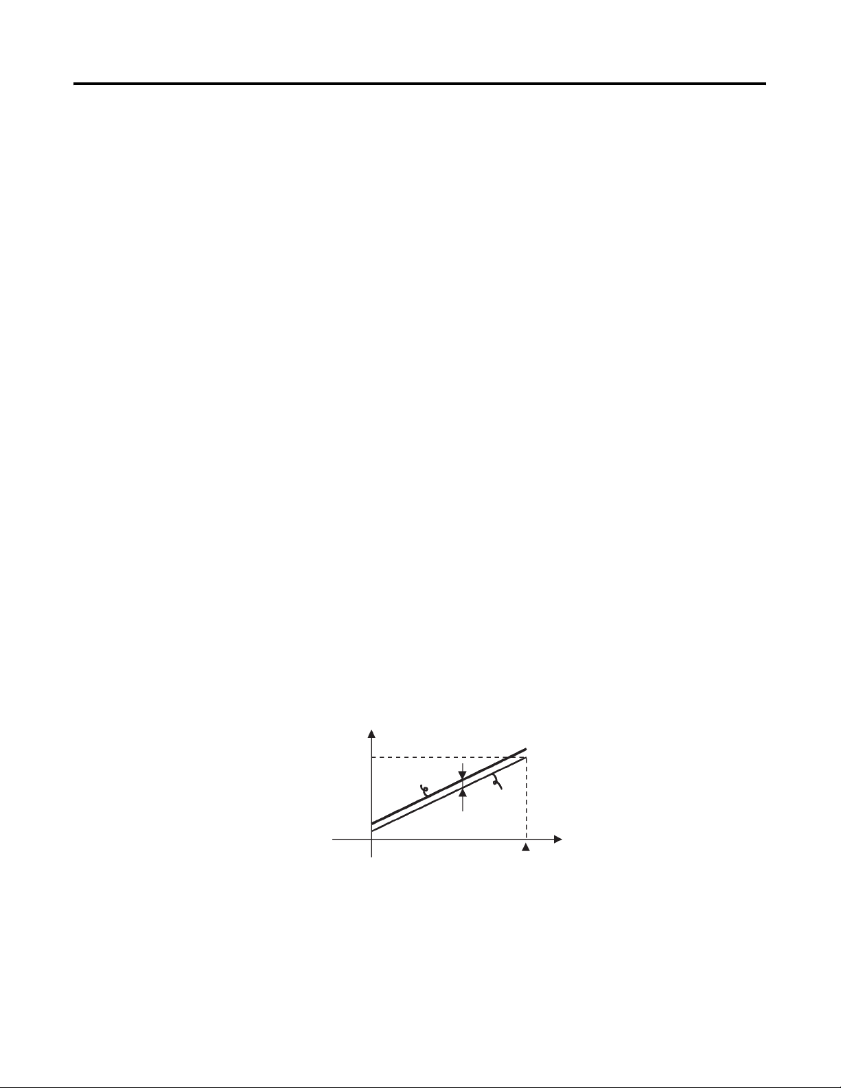
Chapter
Parameter Adjustments and Application
Considerations
4
Shifting Input Values
Overview
The Input Shift parameter allows you to configure the controller to
compensate for possible deviation of the measured temperature (PV) to the
actual temperature at the source (control target). The controller supports two
types of input shifts: 1-point and 2-point. The input shift is automatically
matched to the sensor currently selected by the Input Type parameter (set
value — Table A.D, List of Input Types).
1-Point (Uniform) Shift
Overview
With 1-point shift operation, the Temperature Input Shift parameter
(Adjustment function group) is applied to the entire temperature input range
in a uniform or consistent manner. In other words, the adjusted value is
applied equally to each input/sensor value read by the controller and displayed
as such. For example, if the input shift value is set to 1.2°C, the process value is
treated as by the controller 201.2°C after input shift is applied when the
measured process value is 200°C. (See Figure 4.1.)
Figure 4.1 One-Point Shift
Temperature
Upper-limit
value
Lower-limit
value
0
After shift
Before
shift
Input shift value
Input
100
Example Operation Procedure — Operation Function Group
In this example, apply a 1°C 1-point shift to the input value of a type K
thermocouple sensor.
4-1 Publication 900-UM001C-EN-E - January 2004
Page 72
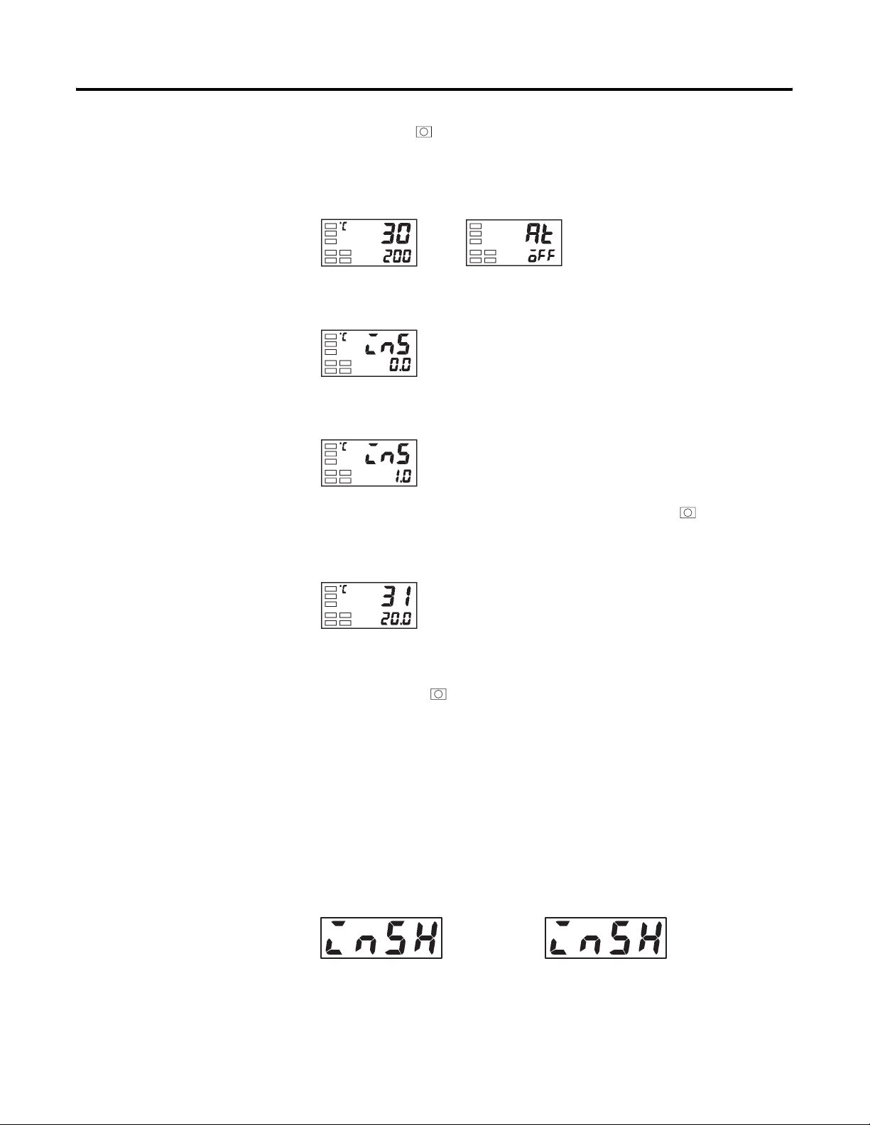
4-2 Parameter Adjustments and Application Considerations
1. Press the key to move from the Operation function group to the
Adjustment function group.
Figure 4.2
Operation function group
2. Select the Temperature Input Shift parameter by pressing the M key.
Figure 4.3
3. Press the U or D key to set 1.
Figure 4.4
Adjustment function group
Temperature
input shift
4. To return to the Operation function group, press the key. The
process value is 1°C larger than before the shift was applied.
Figure 4.5
Operation function group
Note: The newly configured value or parameter is loaded into controller
memory if you do not operate any key on the front panel for at least 2 seconds
or by pressing the or M key.
2-Point Shift
Overview
2-point shift can be applied only to non-contact temperature sensors (infrared
type K thermocouple).
Figure 4.6
Upper-limit
temperature
input shift
value
Upper-limit
temperature
input shift
value
Publication 900-UM001C-EN-E - January 2004
Page 73
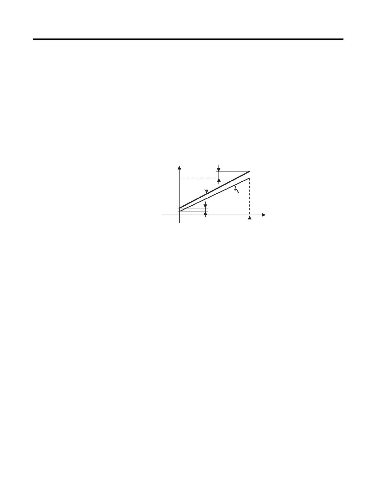
Parameter Adjustments and Application Considerations 4-3
• The input temperature range of non-contact temperature sensors can be
shifted by setting an individual value for the upper and lower end points
of the sensor range. This means that the shift can be applied equally
across the range with separate values for each end of the range. For
example, if the upper-limit value is set to 2°C and the lower-limit value is
set to 1°C, the sensor range is shifted by an average of 1.5°C at the 50%
input.
• Set the upper-limit value in the Upper-Limit Temperature Input Shift
Value parameter and the lower-limit value in the Lower-Limit
Temperature Input Shift Value parameter.
Figure 4.7 Two-Point Shift
Temperature
Upper-limit
value
Upper-limit temperature input shift value
After shift
Before shift
Lower-limit value
0
Lower-limit temperature
input shift value
100
Input
How to Calculate Input Shift Values (2-Point Shift)
When the non-contact temperature sensor (for example, OMRON ES1A
sensor) is connected to the Bulletin 900-TC16, an offset of several degrees to
several tenths of a degree can occur. For this reason, it may be desirable to
offset the readout value by 1-point or 2-point shift as described here. Note:
2-point shift can be carried out only on non-contact temperature sensors, and
cannot be used with other input types.
Preparations
1. Set to the temperature range matching the input specifications of the
non-contact temperature sensor. (The non-contact infrared sensor is
supported only in thermocouple input type Bulletin 900-TC16
controllers. See Tables 1.A and A.D.)
Publication 900-UM001C-EN-E - January 2004
Page 74
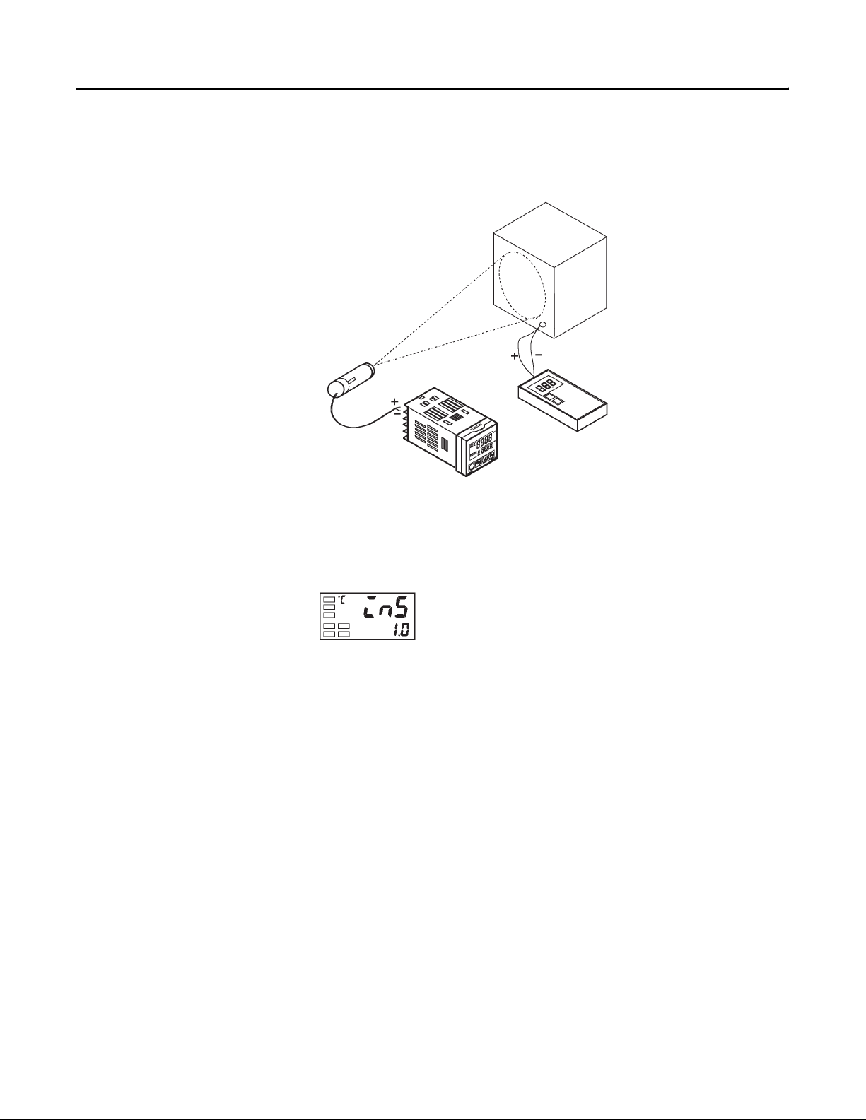
4-4 Parameter Adjustments and Application Considerations
r
a
2. Prepare a thermometer (B) capable of measuring the temperature of the
control target (C) as shown in Figure 4.8 so that 1-point shift or 2-point
shift can be carried out.
Figure 4.8 Configuration when Compensating a Non-Contact Temperature Sensor
Infrared
non-contact
temperature
sensor
(A) 900-TC16
(C) Control target
(B) Thermomete
Using the 1-Point Shift Method
Figure 4.9
1. In the temperature control system configuration shown in Figure 4.8,
bring the set point to near the value at which the temperature of the
control target is to be controlled. Assume that the control target
temperature (C) and the control target temperature (B) match.
Publication 900-UM001C-EN-E - January 2004
2. Check the control target temperature (B) and the controller readout (A).
Take the value from the following equation as the input shift value, and
configure the same numerical value to ins.
Control target temperature (B) Controller readout (A)– Input shift v
=
Figure 4.10 shows the effect of 1-point temperature input shift.
Page 75
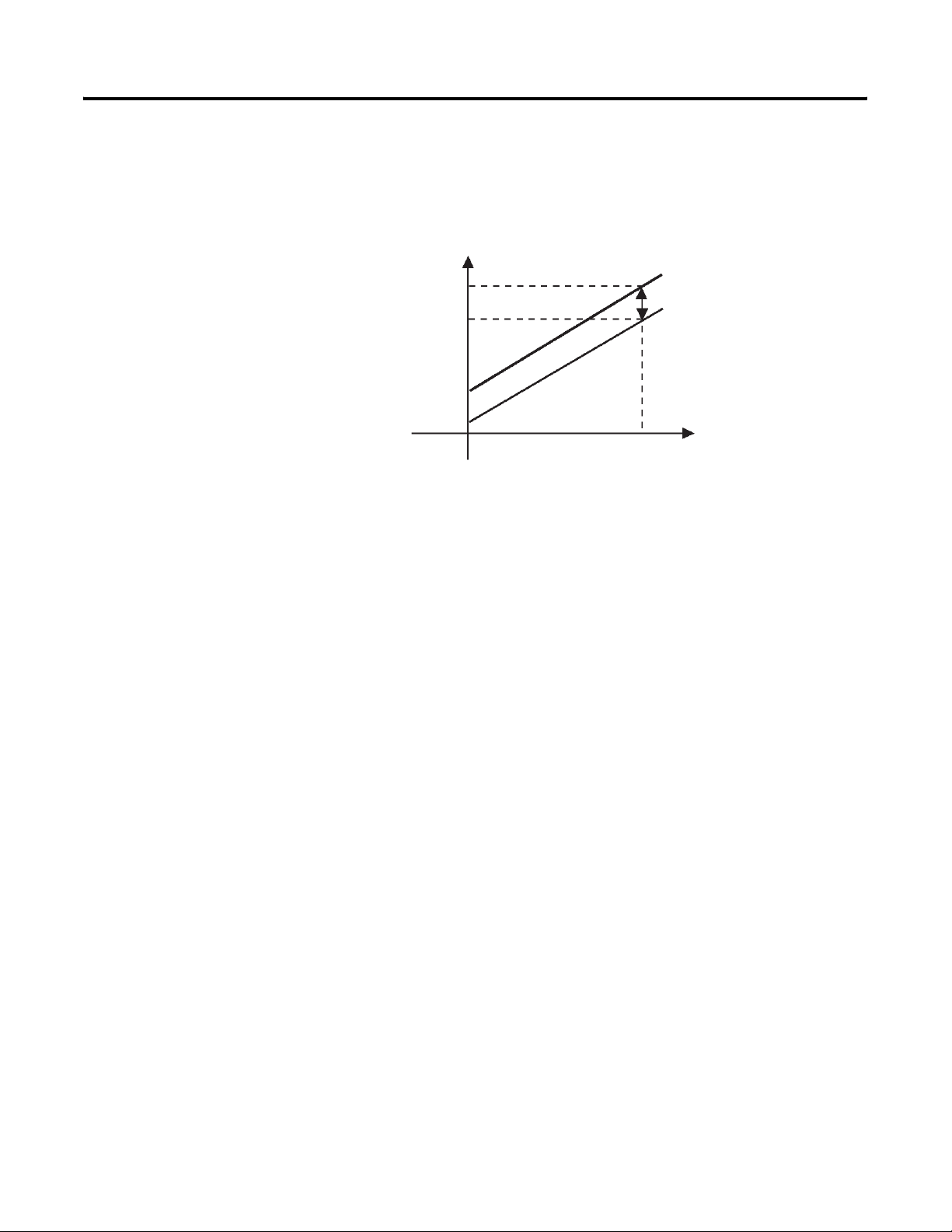
Parameter Adjustments and Application Considerations 4-5
3. After you have configured the 1-point input shift value in the controller,
check the controller readout (A) and control target temperature (B). If
they are almost the same, this completes temperature input shift
procedure.
Figure 4.10 One-Point Temperature Input Shift
Controller readout (A)
Temperature readout
after shift (e.g. 120°C)
Temperature readout
before shift (e.g. 110°C)
0
After shift
Input shift value (e.g. 10°C)
Before shift
Near set point
(e.g. 120°C)
Temperature readout of
control target (B)
Using the 2-Point Shift Method
Use the 2-point input shift feature if you want to increase the accuracy of the
readout values across the range of the non-contact sensor.
1. When using the 2-point shift method, shift the controller readout at two
points: the first near room temperature, and the second near the value at
which the temperature of the control target is to be controlled. Check
control target temperature (B) and controller readout (A) at both points.
2. Using equations 1 and 2 (see p. 4-6) calculate the upper- and lower-limit
temperature input shift values from the readout and temperature to be
shifted that you obtained in step 1.
Figure 4.11 shows the effect of shift by 2-point temperature input shift.
Publication 900-UM001C-EN-E - January 2004
Page 76
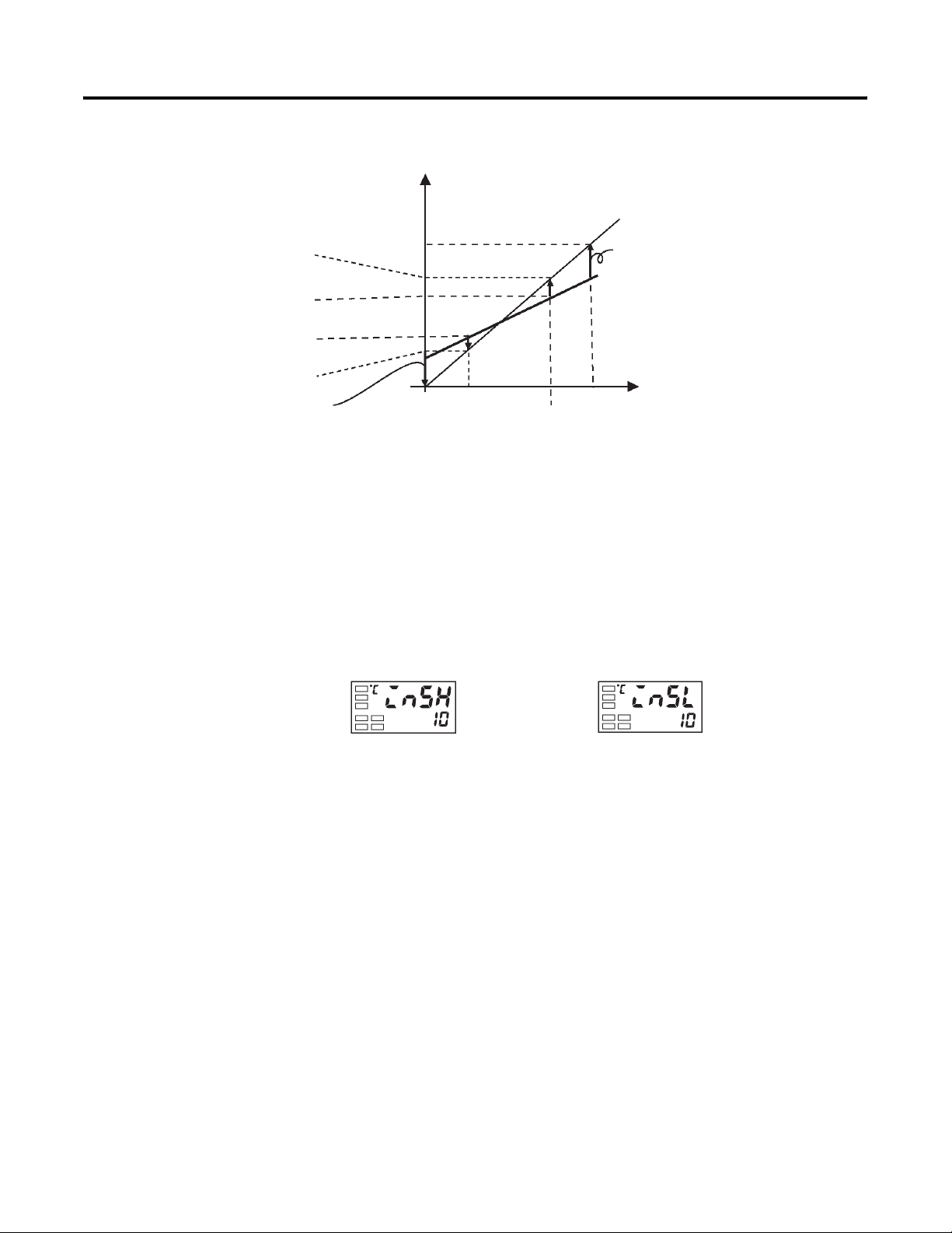
4-6 Parameter Adjustments and Application Considerations
Figure 4.11 Two-Point Temperature Input Shift
Controller readout (A)
Set temperature
upper limit YH
(e.g. 260°C)
After shift
Temperature readout
after input shift X2 (e.g. 110°C)
Temperature readout
before input shift Y2 (e.g. 105°C)
Temperature readout
before input shift Y1 (e.g. 40°C)
Temperature readout
after input shift X1 (e.g. 25°C)
Lower-limit temperature
input shift value
X1 room temperature
0
(e.g. 25°C)
Set temperature
lower limit YL (e.g. 0°C)
– Equation 1: Use the following equation to calculate the lower-limit
temperature input shift value.
insl
– Equation 2: Use the following equation to calculate the upper-limit
temperature input shift value.
insh
Figure 4.12
Adjustment function group
Upper-limit
temperature
input shift value
YL Y1–
--------------------
Y2 Y1–
YH Y1–
--------------------Y2 Y1–
Upper-limit temperature
input shift value
Before shift
Temperature readout of
control target (B)
Near X2 set point (e.g. 110°C)
X2 Y2–()X1 Y1–()–{}X1 Y1–()+×=
X2 Y2–()X1 Y1–()–{}X1 Y1–()+×=
Lower-limit
temperature
input shift value
Publication 900-UM001C-EN-E - January 2004
Note: For meanings of variables, see Figure 4.11.
3. After you have configured the calculated values in the controller to
insl and insh, compare controller readout (A) with the control
target temperature (B).
4. Although the input shift was carried out at two points, close to room
temperature (ambient temperature), and near to the set point, select
points close to each end of the sensor range to improve accuracy across
the full range of the sensor measurement range.
Note: Before selecting these values, check that they will not damage the
control application if applied.
Page 77
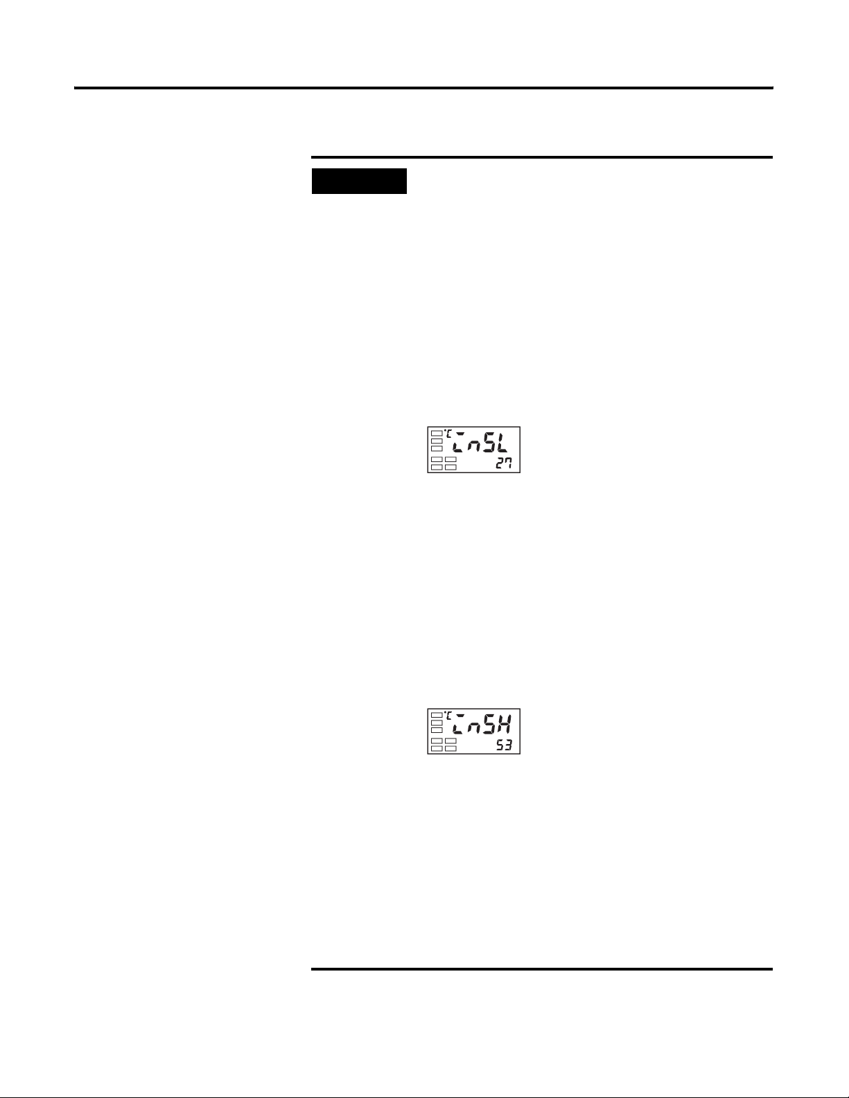
Parameter Adjustments and Application Considerations 4-7
EXAMPLE
In this example, the non-contact (infrared) sensor
type K 0…260°C specification is used to do a 2-point
shift.
YL an YH in equations 1 and 2 are set temperature
lower limit (YL = 0°C) and set temperature upper
limit (YH = 260°C). Check the temperature of the
control target.
When the room temperature (X1) is 25°C, the
readout on the controller (Y1) is 40°C, and when the
temperature near the set point (X2) is 110°C, the
readout on the controller (Y2) becomes 105°C.
Lower-limit temperature input shift value:
Adjustment function group
Lower-limit
temperature input
shift value
110 105–()25 40–()–{}25 40–()+×
insl
040–
-------------------105 40–
-
=
=
–27.3°C
Upper-limit temperature input shift value:
Upper-limit
temperature input
shift value
insh
260 40–
-------------------105 40–
=
110 105–()25 40–()–{}25 40–()+×
–52.7°C
=
Publication 900-UM001C-EN-E - January 2004
Page 78
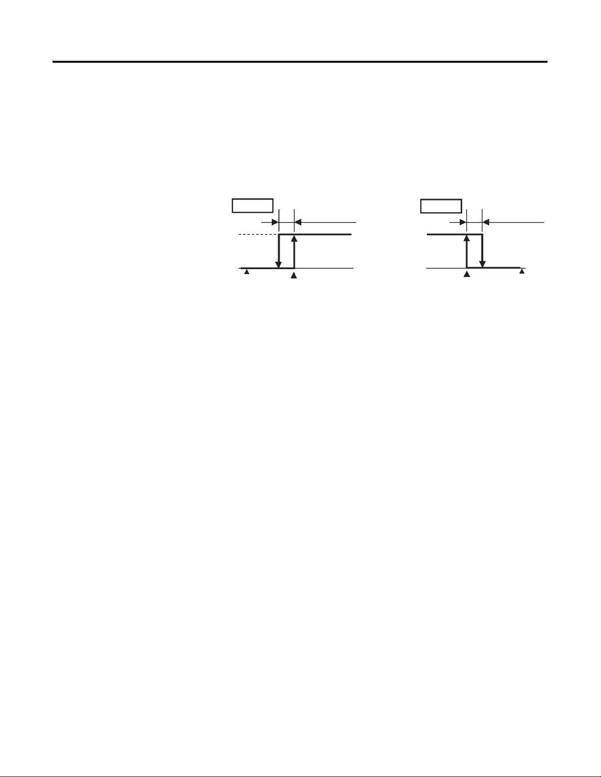
4-8 Parameter Adjustments and Application Considerations
Alarm Functions/ Parameters
Alarm Hysteresis
You can configure how much deviation (hysteresis) is allowed from the alarm
value before the alarm comes ON and resets to OFF. The hysteresis of alarm
outputs, or when alarms are actually switched ON and OFF, can be configured
as follows:
Figure 4.13
Upper-limit
ON
OFF
alarm
Normal
Operating
Area
SP
Alarm hysteresis
Alarm value
Alarm hysteresis is independently set for each alarm (1 and 2) in the Alarm
Hysteresis 1 and Alarm Hysteresis 2 parameters (Advanced Setting function
group). Note: The default is 0.2 (°C or °F depending on your units selection).
ON
OFF
Lower-limit
alarm
Alarm value
Alarm hysteresis
Normal
Operating
Area
SP
Standby Alarm Sequence
Standby alarm sequence is a function which allows you to configure the alarm
outputs to be temporarily disabled until after the first alarm condition occurs.
From then on, the alarm output is active for all future alarm conditions (see
Table 3.H).
For example, in a standard heating application, if you used the standard low
alarm configuration, the alarm would be active as soon as you switch the
controller ON. However, with standby sequence, the alarm output is disabled
during the first warm-up, and the temperature has to rise above the alarm set
point before the alarm can become active. Then, if the temperature falls below
the alarm set point, the output is active.
Restart
As mentioned above, the standby sequence is canceled after the first real alarm
condition clears. If desired, it can be restarted later by the Standby Sequence
Reset parameter (Advanced Setting function group). For details, see p. 5-40,
Standby Sequence Reset Method.
Publication 900-UM001C-EN-E - January 2004
Page 79
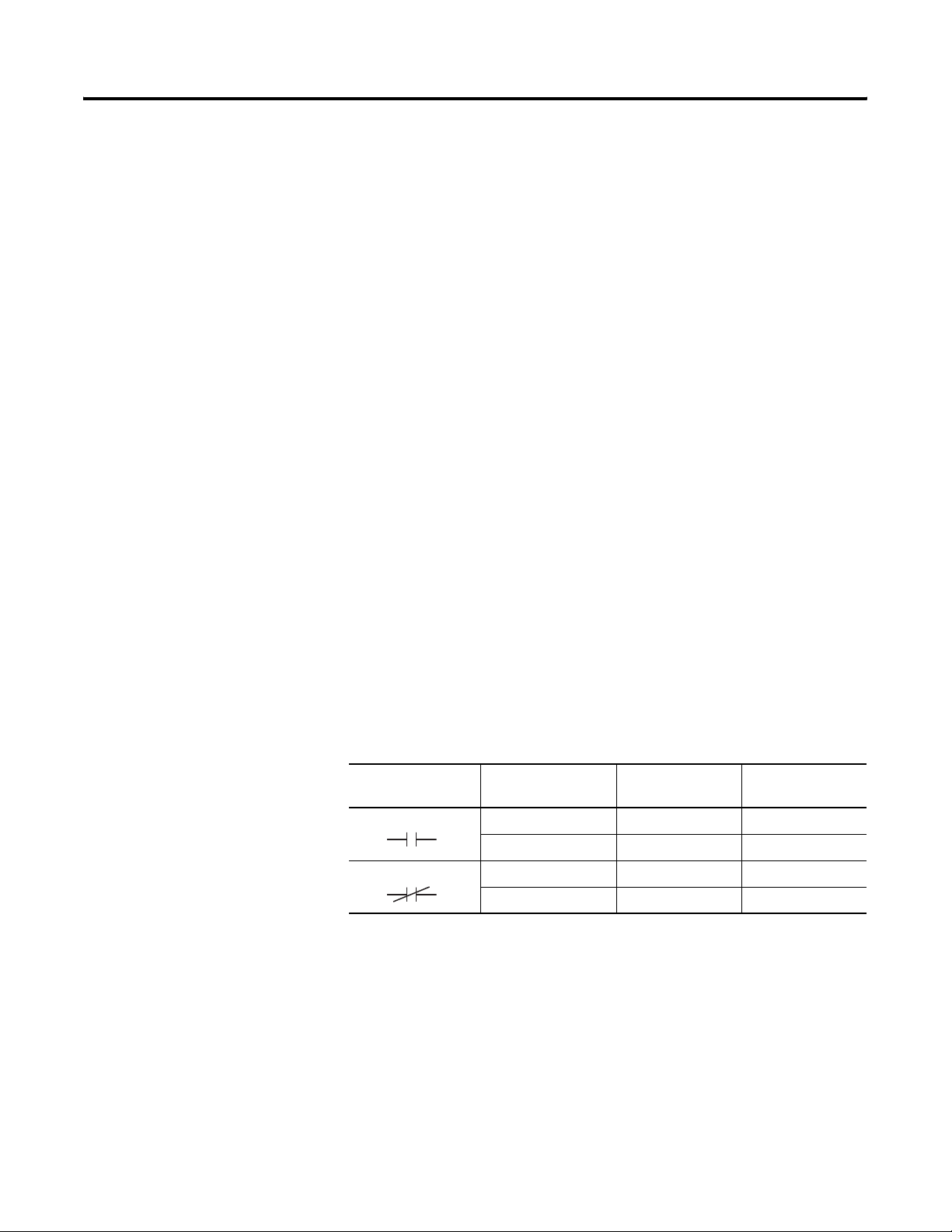
Parameter Adjustments and Application Considerations 4-9
Alarm Latch
Alarm latch is a function where you can configure the alarm output once
turned ON to stay ON regardless of the process temperature.
The alarm latch function can be canceled by turning the controller power OFF.
(Note, however, that it can also be canceled by switching to the Initial Setting
function group, Communications Setting function group, Advanced Setting
function group, or Calibration function group.
Alarm Output Close in Alarm or Open in Alarm
When the Bulletin 900-TC16 alarm output(s) is configured to close in alarm,
the status of the alarm output is normally open. When configured to open in
alarm, the status of the alarm output is inverted or, in relay logic terms,
normally closed (see Table 4.A).
The alarm type (see Table 3.H) and Close in Alarm (normally open)/Open in
Alarm (normally closed) parameters can be independently configured for each
alarm output.
The close in Alarm/Open in Alarm condition is configured in the Alarm 1 and
2 Open in Alarm parameters in the Advanced Setting function group. Note:
The default is n-o: close in alarm.
Table 4.A
Parameter
Configuration
Close in alarm ON ON Lit
Open in alarm ON OFF Lit
Alarm
Condition
OFF OFF Out
OFF ON Out
Alarm
Output
Alarm
LCD
The alarm output turns OFF (relay contact open) during a power interruption
to the controller and for about 2 seconds after the power is turned ON
regardless of the close in alarm/open in alarm configuration.
Publication 900-UM001C-EN-E - January 2004
Page 80
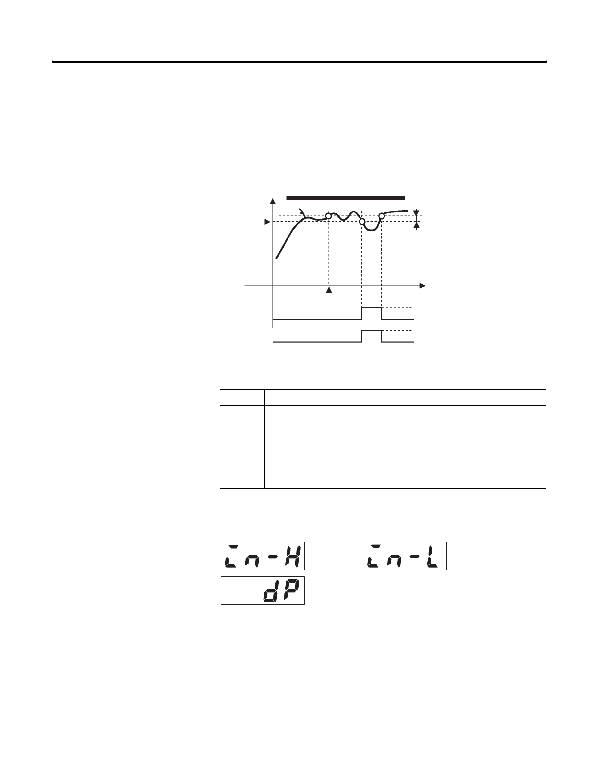
4-10 Parameter Adjustments and Application Considerations
Summary of Alarm Operations
Figure 4.14 below visually summarizes the description of alarm operations
when alarm type is set to lower-limit alarm with standby sequence and the
Bulletin 900-TC16 is configured to close in alarm.
Figure 4.14
Alarm value
Alarm
output
Alarm type: lower-limit alarm with
standby sequence
PV
Standby sequence
canceled
Alarm hysteresis
Time
ON
OFF
ON (closed)
OFF (open)
Configuration of Scaling
Upper and Lower Limits
(0…50 mV Analog Input)
Table 4.B Alarm Parameters
Symbol Parameter: Function Group Description
alh_ Alarm 1 and 2 Hysteresis:
Alarm
Advanced Setting function group
rest Standby Sequence Reset Method:
Alarm
Advanced Setting function group
al_n Alarm 1 and 2 Open in Alarm:
Alarm
Advanced Setting function group
_ = Output 1 or 2
Figure 4.15
Scaling
upper
limit
Decimal
point
Overview
Scaling
lower limit
Publication 900-UM001C-EN-E - January 2004
When an analog input (0…50 mV voltage input) is selected, scaling to specific
engineering units (e.g., lbs) that match the application is possible.
Page 81
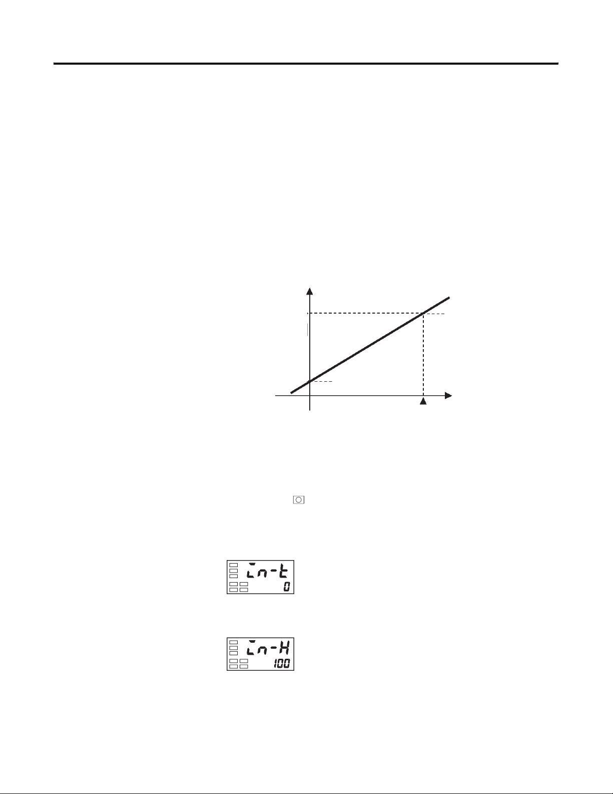
Parameter Adjustments and Application Considerations 4-11
Scaling is set in the Scaling Upper Limit, Scaling Lower Limit, and Decimal
Point parameters (Initial Setting function group). These parameters cannot be
used when a temperature input type is (e.g., RTD) selected.
The Scaling Upper Limit parameter allows you to configure the physical
quantity to be expressed by the upper limit input value, and the Scaling Lower
Limit parameter allows you to configure the physical quantity to be expressed
by the lower-limit input value. The Decimal Point parameter specifies the
number of digits past the decimal point.
Figure 4.16 shows a scaling example of a 0…50 mV input. After scaling, the
sensor input can be directly read from the controller as a percentage of
humidity. However, the display will not indicate %, only a value.
Figure 4.16 Input Scaling
Readout
(humidity)
Upper-limit value (95.0%)
50 mV
Lower-limit value (10.0%)
0
0mV
100%FS
Input
(0…50 mV)
Example Operation Procedure
In this example, configure the scaling upper- and lower-limits so that inputs
0…50 mV become 10.0% to 95.0%.
1. Press the key for at least 3 seconds to move from the Operation
function group to the Initial Setting function group.
Figure 4.17
Initial Setting function group
Input type
2. Select Scaling Upper Limit by pressing M.
Figure 4.18
Scaling upper
limit
Publication 900-UM001C-EN-E - January 2004
Page 82
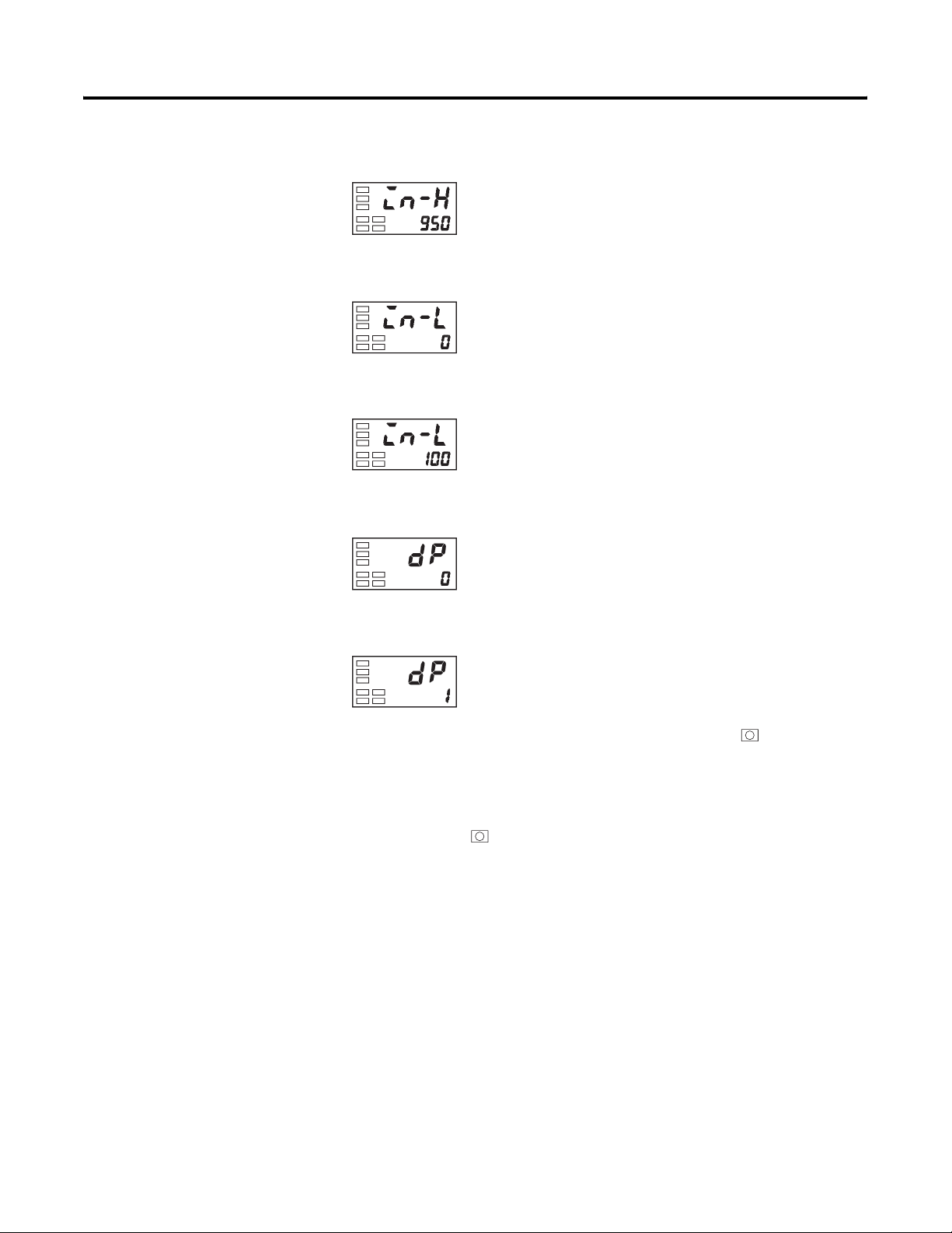
4-12 Parameter Adjustments and Application Considerations
3. Press the U or D key to set the parameter to 950.
Figure 4.19
4. Select Scaling Lower Limit by pressing M.
Figure 4.20
5. Press the U or D key to set the parameter to 100.
Figure 4.21
6. Select the decimal point position by pressing M.
Figure 4.22
Scaling lower
limit
Decimal point
Executing the Heating and Cooling Control Mode
7. Press the U or D key to set the parameter to 1.
Figure 4.23
8. To return to the Operation function group press the key for at least
1 second.
Note: The newly configured value or parameter is loaded into controller
memory if you do not operate any key on the front panel for at least 2 seconds
or by pressing the or M key.
Overview
Several forms/modes of heating, cooling, or heating and cooling control can
be used with the Bulletin 900-TC16 controller. The heating and cooling
control mode operates when h-c: heating and cooling is selected in the
Standard/Heating and Cooling parameter from the Initial Setting function
group. Select the control mode according to the Table 4.C:
Publication 900-UM001C-EN-E - January 2004
Page 83
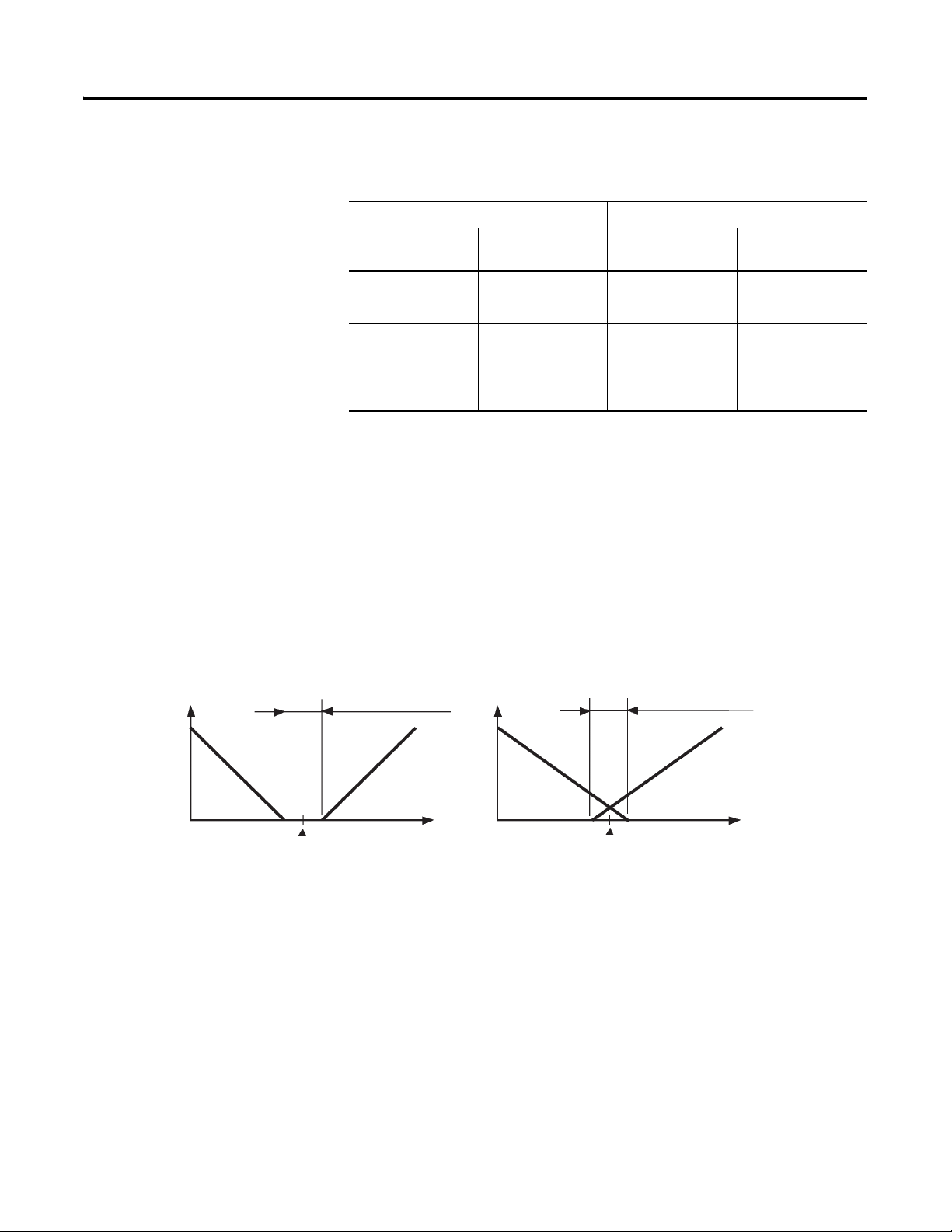
Parameter Adjustments and Application Considerations 4-13
Table 4.C Output to Control Mode Assignment
Setting Output
Output
Control Mode Direct/Reverse
Operation
Control Output 1 Control Output 2
(ALM2)
Standard control Reverse operation Control output (heat) —
Standard control Direct operation Control output (cool) —
Heating and cooling
Reverse operation Control output (heat) Control output (cool)
control
Heating and cooling
Direct operation Control output (cool) Control output (heat)
control
Note: The default is heating control (standard control mode, reverse
operation).
Dead Band (Heating and Cooling Control)
When the heating and cooling control method is selected, the Dead Band
parameter can be used. The dead band is configured with the set point as its
center (see Figure 4.24). The dead band width is the configured value of the
Dead Band parameter (Adjustment function group). Setting a negative dead
band value produces an overlap band. Note: The default is 0.0%EU.
Figure 4.24 Dead Band
Dead band:
dead band width = positive
Output
Overlap band:
dead band width = negative
Heating side
Set point
Cooling side
Heating side Cooling side
PV PV
Set point
Publication 900-UM001C-EN-E - January 2004
Page 84
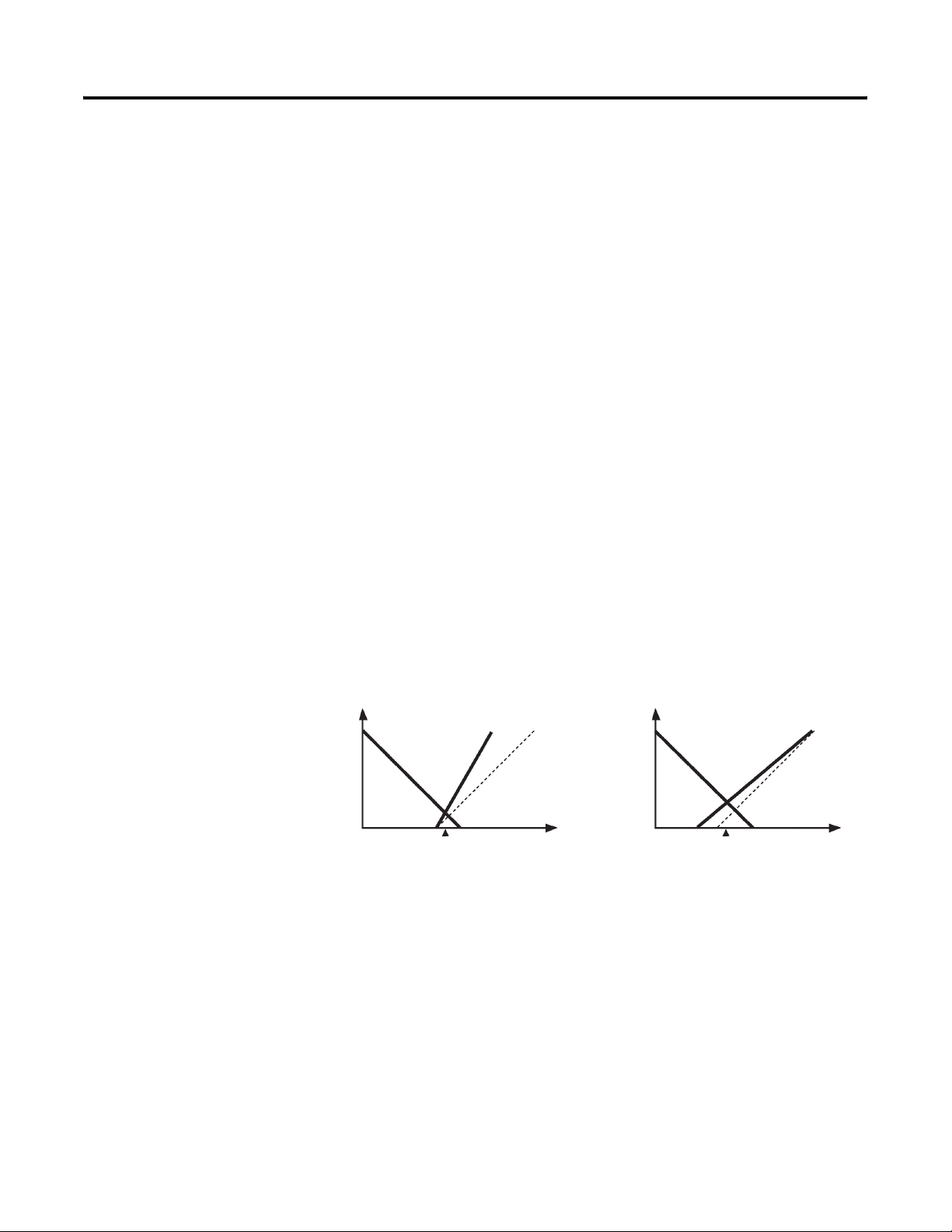
4-14 Parameter Adjustments and Application Considerations
Cooling Coefficient (Heating and Cooling Control)
When the heating and cooling control mode and PID control method are
selected, the Cooling Coefficient parameter can be used. If the heating and
cooling functional characteristics of the control target greatly differ, this could
limit satisfactory control performance from being obtained by the same PID
values. To reduce the possibility of this occurring, adjust the proportional band
(P) at the cooling side of the set point using the cooling coefficient to balance
control between the heating and cooling sides. In heating and cooling control,
the proportional band (P) at the heating or cooling (output) side is calculated
by the following formula:
Control output 1 (heating side): P P=
control output 2 (cooling side): P P cooling (output 2) coefficient×=
(See Figure 4.25.)
The control output 2 (cooling side) coefficient is applied to the control
output 1 (heating side) proportional band (P) to obtain control with
characteristics that differ from those at control output 1 (heating side).
Figure 4.25 Cooling Coefficient
Output
Control output
1 Heating
side P
Control output 2
Cooling side P
Set point
Control output 1 side Px0.8
Control output 1 side
Px1.0
PV PV
Output
Control output 1 side
Px1.0
Control output
1 Heating
side P
Control output 1 side Px1.5
Set point
Control output 2
Cooling side P
Setup of Heating and Cooling
To configure the heating and cooling control mode, set the Standard/Heating
and Cooling, Dead Band, and Cooling Coefficient (when using PID)
parameters.
Publication 900-UM001C-EN-E - January 2004
Page 85
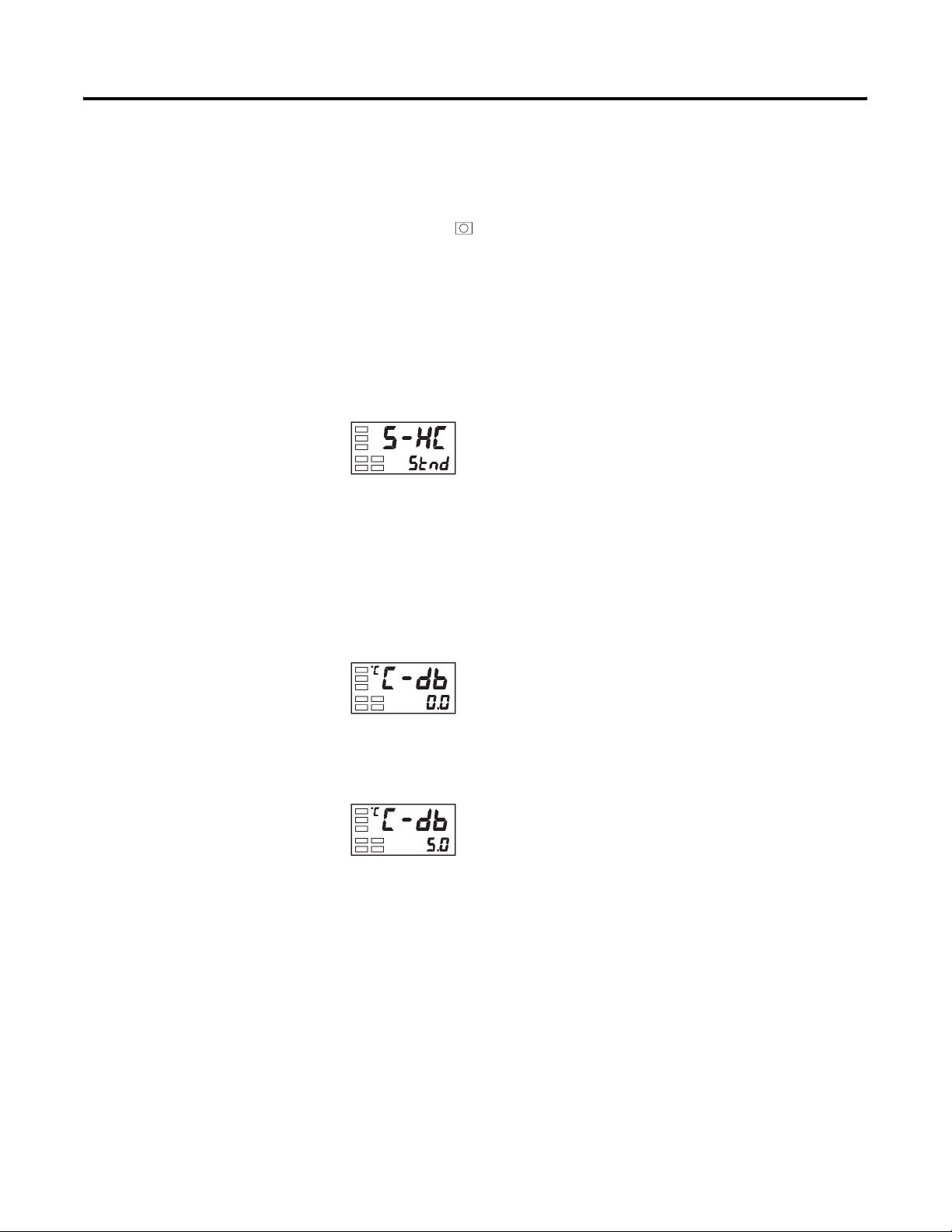
Parameter Adjustments and Application Considerations 4-15
Example Operation Procedure — Heating and Cooling Control Selection
Standard/heating and cooling = Heating and cooling
1. Press the key for at least 3 seconds to move from the Operation
function group to the Initial Setting function group.
2. Select heating and cooling control in the Initial Setting function group.
stnd: Standard control
h-g: Heating and cooling control
Figure 4.26
Initial setting level
Standard/heating
and cooling
Example Operation Procedure — Configuring the Dead Band
Dead band = 5
1. Select Dead Band in the Adjustment function group.
Figure 4.27
Adjustment function group
Dead band
2. Press the U key to set the parameter to 5.0. The setting range is
–199.9…+999.9.
Figure 4.28
Publication 900-UM001C-EN-E - January 2004
Page 86
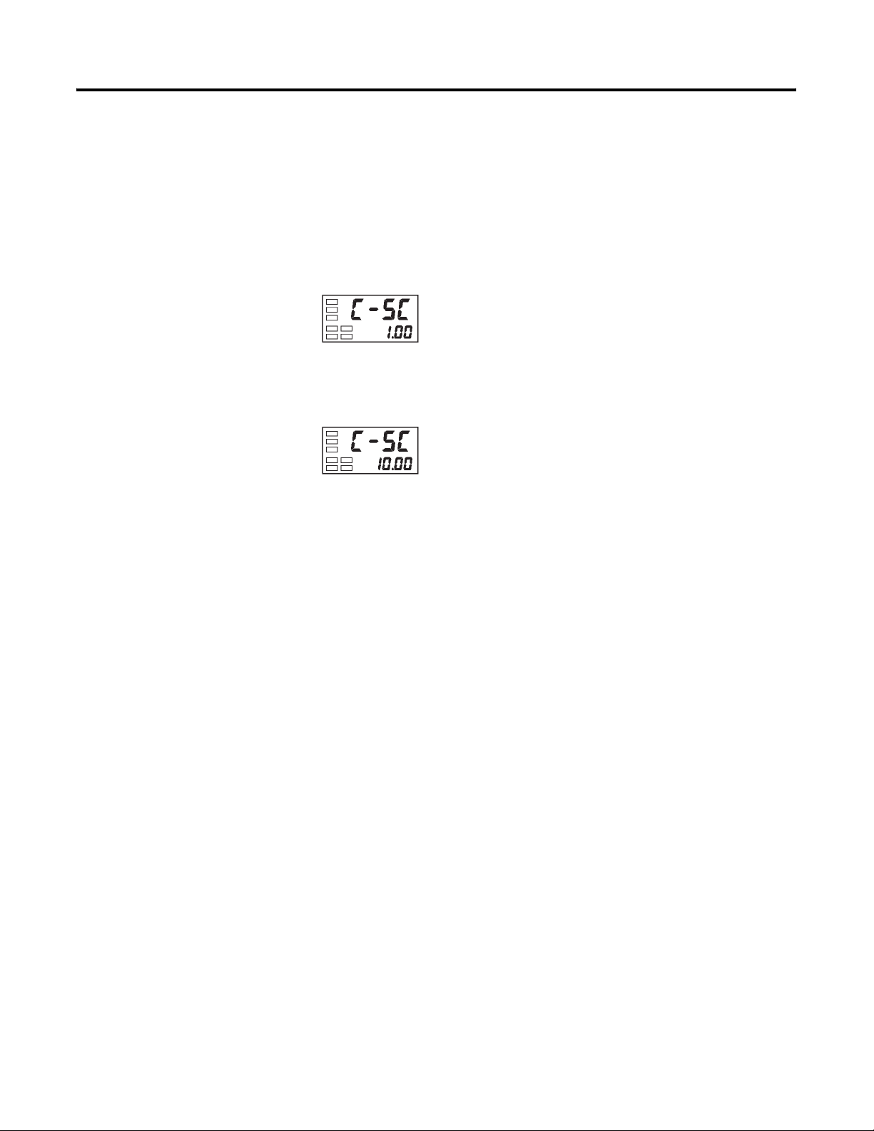
4-16 Parameter Adjustments and Application Considerations
Example Operation Procedure — Configuring the Cooling Coefficient
Cooling coefficient = 10
1. Select Cooling Coefficient in the Adjustment function group. In this
example, set the parameter to 10.
Figure 4.29
Adjustment function group
2. Press the U key to set the parameter to 10.00. The setting range is
0.01…99.99.
Figure 4.30
Cooling
coefficient
Using the Event Input Feature
Overview
Discrete (ON/OFF) inputs can be wired to the Bulletin 900-TC16 (option
unit Cat. No. 900-TC16EIM or 900-TC16ACEIM installed) to cause the
controller to perform several pre-defined/pre-configured tasks. These inputs
are generically called event inputs. The pre-defined functions provided are
controller RUN/STOP control and/or multi-set point selection.
Setting Event Input
RUN/STOP operation of the controller and multi-set point capability can be
executed by the Event Input Assignment 1 and 2 parameters. Table 4.D shows
which functions are assigned to event inputs 1 and 2.
RUN/STOP is assigned to inputs not used for multi-SP of event inputs 1 and
2 by the Event Input Assignments 1 and 2 configured in the Advanced Setting
function group.
Publication 900-UM001C-EN-E - January 2004
Page 87
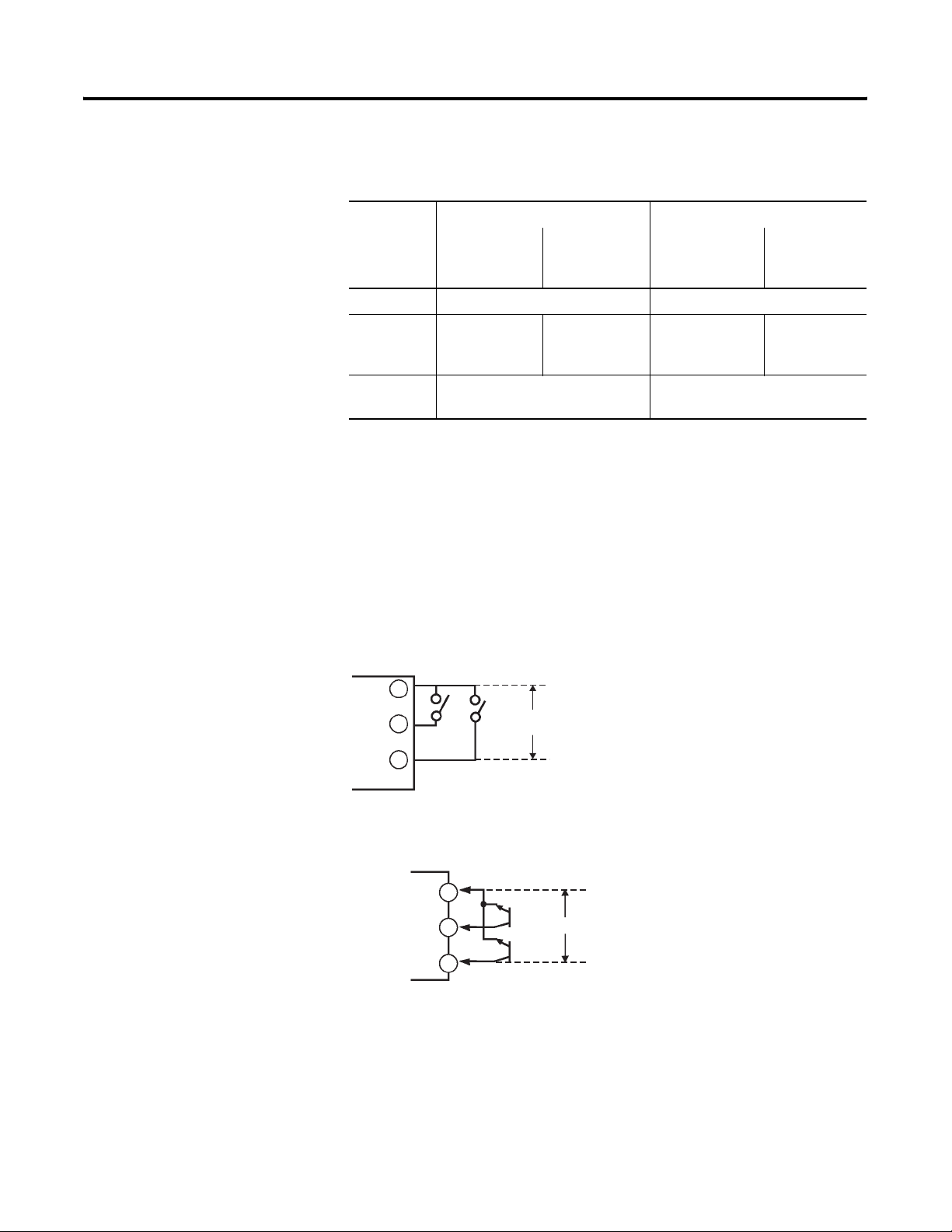
Table 4.D
Parameter Adjustments and Application Considerations 4-17
Number of
Multi-SP
Uses
Parameter
Event Input
Assignment 1
Parameter
Configuration Event Input Function
Event Input
Event Input 1 Event Input 2
Assignment 2
Parameter
0 NONE or STOP ➊ NONE or RUN/STOP switching ➊
1 — (not
displayed)
NONE or STOP Multi-SP 2 set
points (set point
0/1 switching)
NONE or
RUN/STOP
switching
2 — (not displayed) Multi-SP 4 set points
(set point 0/1/2/3 switching)
➊ STOP (RUN/STOP) switching can be set only on one of event input assignments 1 or 2. The event input on the
side that is set can be used. The setting on the other side becomes NONE.
When you want to configure two external inputs to be used to change the
controller set points, use in the Number of Multi-SP Uses parameter.
Two set points (0 or 1) can be selected when the Number of Multi-SP Uses
parameter is set to 1 (default). This setting need not be changed. Set point 0 or
1 is specified by the ON/OFF state of event input 1.
Figure 4.31 Event Inputs
900-TC16
11
12
13
Contact
Inputs
Temperature
Controller
EV1 EV2
11
-
12
+
13
+
Note:
EV1
EV2
Do not connect any
external power source
to these terminals. The
controller sources power
to the inputs.
Do not apply an external voltage source
Note:
to the Event Input Terminals.
Publication 900-UM001C-EN-E - January 2004
Page 88

4-18 Parameter Adjustments and Application Considerations
Multi-SP
Selecting Multi-SP by Event Input
Multi-SP by event input is a function for setting the value of set points 0…3 in
advance, and selecting these set points by combination of event inputs 1 and 2.
Multi-SP selection from external (event) inputs can be used when the option
event input unit Cat. No. 900-TC16EIM or 900-TC16ACEIM is mounted in
the Bulletin 900-TC16 and the Number of Multi-SP Uses parameter is
configured to 1 or 2 (see Tables 4.D, 4.E, and 4.F).
Table 4.E When Number Of Multi-SP Uses Parameter is Set to 1
Event Input 1 Selected Set Point
OFF Set point 0
ON Set point 1
Table 4.F When Number of Multi-SP Uses Parameter is Set to 2
Event Input 1 Event Input 2 Selected Set Point
OFF OFF Set point 0
ON OFF Set point 1
OFF ON Set point 2
ON ON Set point 3
Note: The option unit Cat. No. 900-TC16EIM or 900-TC16ACEIM must be
installed in the Bulletin 900-TC16 controller to use the event input feature.
The input must be on for 50 ms minimum for the controller to recognize its
operation.
Selecting Multi-SP by Keypad Operation
You can select set points 0…3 from the controller keypad by properly
configuring the value of the Multi-SP parameter. To change set points from the
controller keypad, the Multi-SP parameter conditions are as follows:
• When the option event input unit Cat. No. 900-TC16EIM or
900-TC16ACEIM is not mounted in the Bulletin 900-TC16, and
multi-SP is configured as ON, or
Publication 900-UM001C-EN-E - January 2004
• When the option event input unit Cat. No. 900-TC16EIM or
900-TC16ACEIM is mounted in the Bulletin 900-TC16, the Number of
Multi-SP Uses parameter is configured to 0 and the Multi-SP parameter
is configured to ON.
Page 89
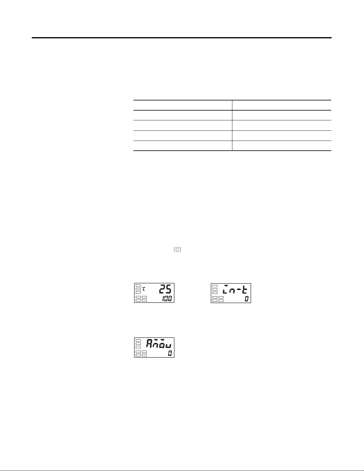
Parameter Adjustments and Application Considerations 4-19
The following table shows the relationship between the Multi SP parameter
value and the selected set point.
Table 4.G
Multi-SP Value Selected Set Point
0 Set point 0
1 Set point 1
2 Set point 2
3 Set point 3
Multi-SP Setup
Example Operation Procedure — to Select Set Points (0/1/2/3)
Before you configure the Number of Multi SP Uses parameter, you must first
cancel protection from the Advanced Setting function group. For additional
details on how to cancel protection, see p. 4-28, Using the Key Protect Function
Group.
1. Press the key for at least 3 seconds to move from the Operation
function group to the Initial Setting function group.
Figure 4.32
Operation function group
PV/SP
Initial Setting function group
Input type
2. Select Move to Advanced Setting Function Group by pressing the M
key.
Figure 4.33
Move to advanced
setting function
group
Publication 900-UM001C-EN-E - January 2004
Page 90
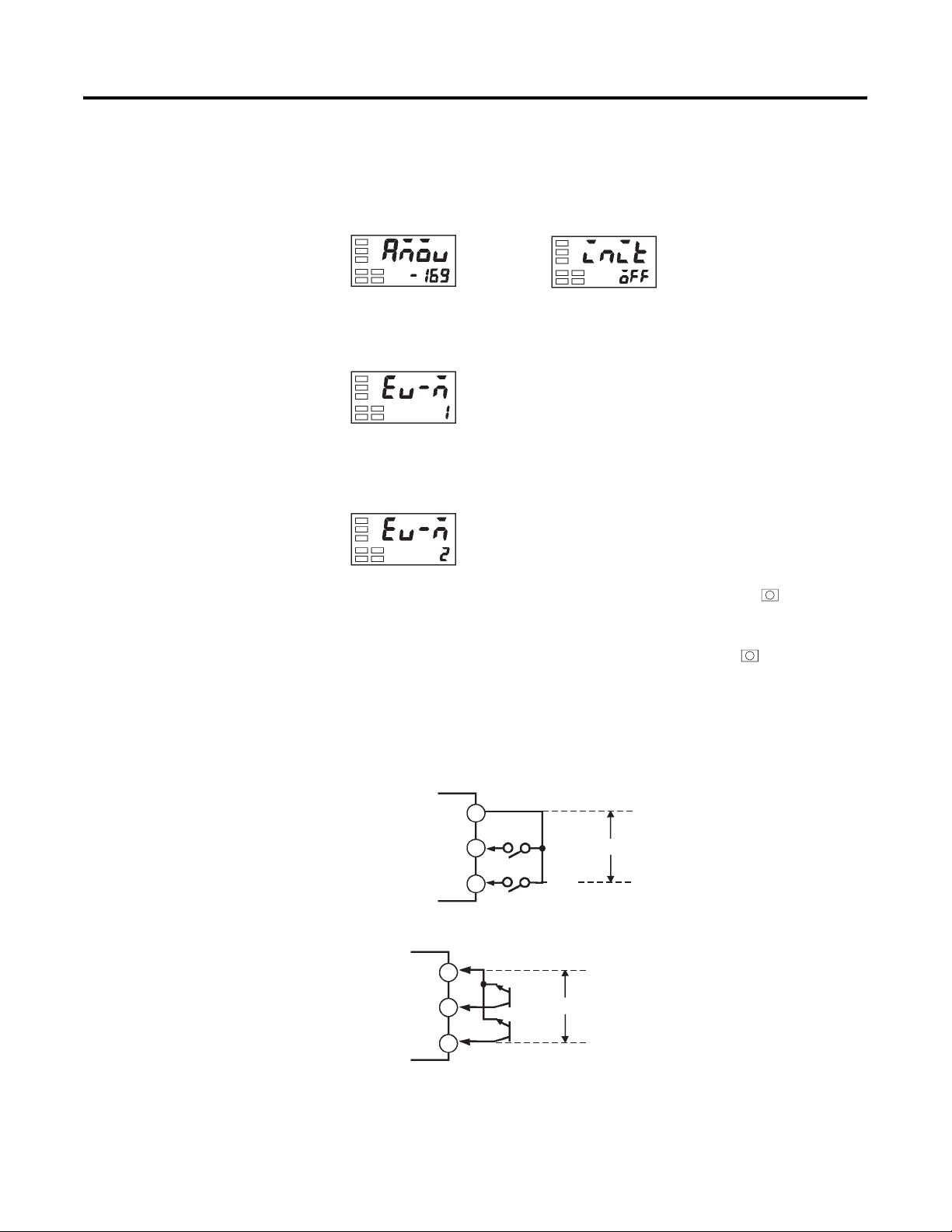
4-20 Parameter Adjustments and Application Considerations
3. Press the D key to enter the password (–169) to cancel protection. You
can now move to the Advanced Setting function group by pressing the
M key or leaving the setting for at least 2 seconds.
Figure 4.34
4. Select Number of Multi-SP Uses parameter by pressing the M key.
Figure 4.35
Number of multi-SP uses setting
5. Press the U key to set the parameter to 2. This allows set point change
from event inputs (see Table 4.D).
Figure 4.36
Advanced setting function group
Parameter
initialize
Number of
multi-SP uses
6. To return to the Initial Setting function group press the key for at
least 1 second.
7. To return to the Operation function group press the key for at least
1 second.
The pre-configured values for set points 0, 1, 2, and 3 are now selectable
according to the ON/OFF states of event inputs 1 and 2.
Figure 4.37 Event Inputs
Temperature
controller
Temperature
Controller
11
12
13
11
Do not apply an external voltage source
Note:
to the Event Input Terminals.
EV1
EV2
EV1
EV2
Do not apply an external voltage source
Note:
to the Event Input Terminals.
12
13
-
+
+
Publication 900-UM001C-EN-E - January 2004
Page 91

Parameter Adjustments and Application Considerations 4-21
Executing RUN/STOP Controller Mode Change
When the Event Input Assignment 1 or Event Input Assignment 2 parameter
is set to RUN/STOP (see Table 4.I), control is started (RUN) when event
input 1 or 2 is OFF. Control is stopped when event input 1 or 2 is ON. While
control is stopped, the controller’s STP (stop) display lights.
Table 4.H
Setting Input Contact Controller Mode
Event input 1 or 2 ON STOP
Event input 1 or 2 OFF RUN
Note: The Multi-SP Uses parameter must be set to 0 or 1 for RUN/STOP
control by event inputs to function (see Table 4.I).
The function of Event Input Assignment 1 and 2 parameters is as follows
according to the Number of Multi-SP Uses parameter value configured.
Table 4.I
Number of
Multi-SP
Uses
Parameter
Setting
0 NONE STOP NONE RUN/STOP
1 — (setting data
2 — (setting data
➊ Default configuration
Event Input
Assignment 1
Parameter
STOP ➊ NONE ➊ RUN/STOP
NONE NONE NONE NONE
not displayed)
— (setting data
not displayed)
not displayed)
Configuration Event Input Function
Event Input
Assignment 2
Parameter
STOP Multi-SP 2 set
NONE Multi-SP 2 set
— (setting data
not displayed)
Event Input 1 Event Input
2
switching
NONE ➊
switching ➊
RUN/STOP
points (set point
0/1 switching)
points (set point
0/1 switching)
Multi-SP 4 set points
(set point 0/1/2/3 switching)
switching
NONE or
RUN/STOP
switching
Publication 900-UM001C-EN-E - January 2004
Page 92
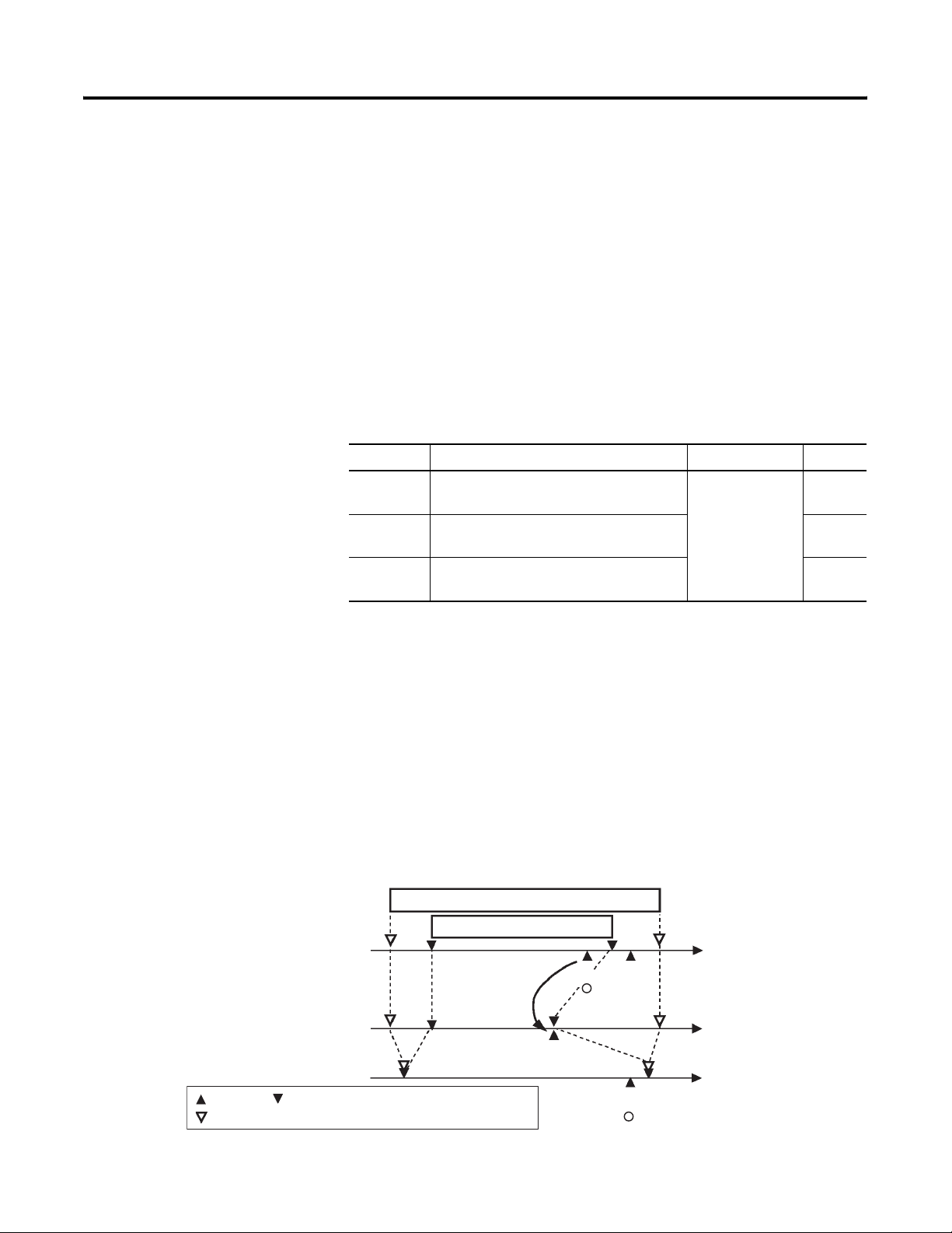
4-22 Parameter Adjustments and Application Considerations
• When the Number of Multi-SP Uses parameter is configured to either 1
or 2, and the Event Input Assignment 1 or 2 parameter is configured to
not displayed, the setting automatically be comes none.
• When the Number of Multi-SP Uses parameter is configured to 0, and it
is possible that both Event Input Assignment 1 and 2 parameters can be
ON, RUN/STOP is assigned to only one event assignment. The other
Event Input Assignment is automatically set to OFF.
• When the RUN/STOP mode function is selected by event inputs,
RUN/STOP at the run level is not displayed.
Table 4.J Parameters
Symbol Parameters: Function Group Description Page
Configuring the Upper and Lower Set Point (SP) Limit Values
Setting range
Changed to upper
limit value
Input type changed
Set point Upper- and lower-limit values of the limitter
Sensor upper- and lower-limit values
ev-1 Event Input 1 Assignment:
Advanced Setting function group
ev-2 Event Input 2 Assignment:
For selecting the
event input
function
5-38
5-38
Advanced Setting function group
ev-n Number of Multi-SP Uses:
5-37
Advanced Setting function group
Set Point Limitter
The maximum configurable range of the set point is limited by the Set Point
limitter function. The set point limitter is used to prevent someone from
configuring the set point to some value outside the maximum range called for
by the application, thereby preventing the control target from reaching
abnormal temperatures. The upper- and lower-limit values of the set point
limitter are configured from the Set Point Upper Limit and Set Point Lower
Limit parameters in the Initial Setting function group, respectively.
Figure 4.38
Sensor range
Set point limitter
Set point
A
Changed to the
new upper limit
value
C
B
x
Set point
Set point
B
(setting possible)
(setting not possible)
x
Publication 900-UM001C-EN-E - January 2004
Page 93
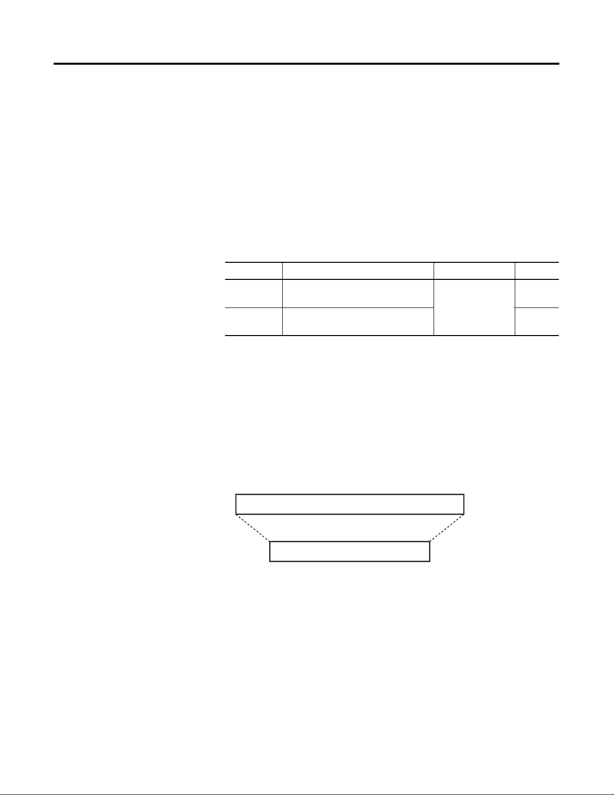
Parameter Adjustments and Application Considerations 4-23
Application Considerations
• If a change is made to the set point upper and/or lower limit value with
the current set point outside the limitter range, the set point is forcibly
changed by the controller to the sensor’s upper SP limit or lower SP
limit value, whichever is closer.
• When the input type or temperature unit are changed, the set point
limits are forcibly reset to the sensor range.
Table 4.K Parameters
Symbol Parameters: Function Group Description Page
sl-h Set Point Upper Limit: Initial Setting
function group
sl-l Set Point Lower Limit: Initial Setting
function group
For limiting the SP
setting
5-28
5-28
Set Point Limit Setup
To configure the Set Point Upper and Lower Limit parameters, you must be in
the Initial Setting function group. The following example describes how to
configure the set point limit when using a type K thermocouple (normal full
range: –200…1300°C).
Figure 4.39
-200 1300
Normal/Full Sensor range (Type K thermocouple)
Set point limitter range
1000-100
Publication 900-UM001C-EN-E - January 2004
Page 94
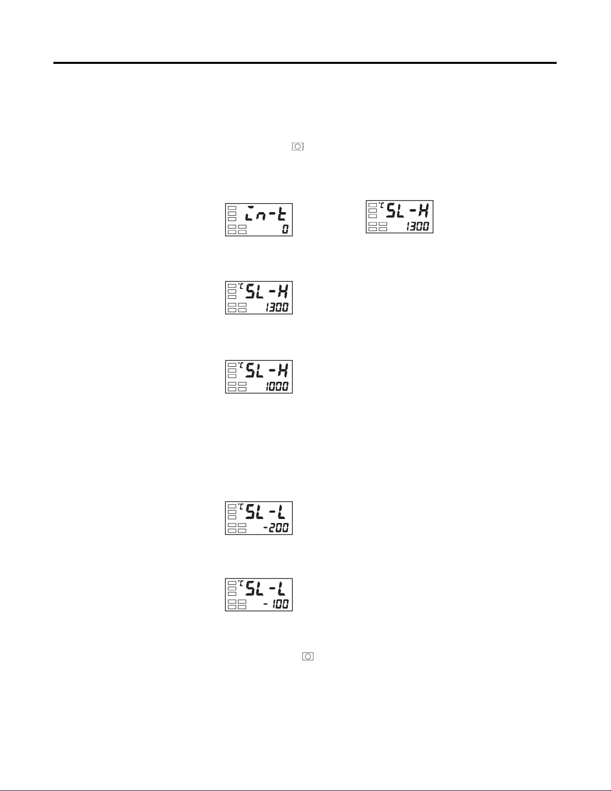
4-24 Parameter Adjustments and Application Considerations
Example Operation Procedure — Configuring the Set Point Upper Limit
Configure the Set Point Upper Limit parameter value to 1000.
1. Press the key for at least 3 seconds to move from the Operation
function group to the Initial Setting function group.
Figure 4.40
Initial setting level
2. Select Set Point Upper Limit parameter.
Figure 4.41
3. Press the U or D key to configure the parameter value to 1000.
Figure 4.42
Input type
Set point
upper limit
Set point
upper limit
Example Operation Procedure — Configuring the Set Point Lower Limit
Configure the Set Point Lower Limit parameter value to –100.
1. Select Set Point Lower Limit in the Initial Setting function group.
Figure 4.43
Set point lower
limit
2. Press the U or D key to configure the parameter value to –100.
Figure 4.44
Note: The newly configured value or parameter is loaded into controller
memory if you do not operate any key on the front panel for at least 2 seconds
or by pressing the or M key.
Publication 900-UM001C-EN-E - January 2004
Page 95
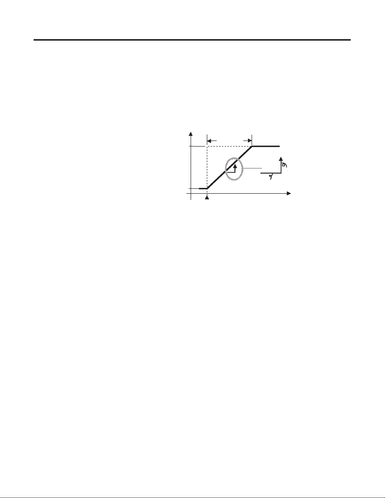
Parameter Adjustments and Application Considerations 4-25
Executing the SP Ramp Function (Limiting the SP Rate of Change)
SP Ramp
With the SP ramp function, the controller can limit the rate at which a change
in the set point will impact the control according to the user-defined SP ramp
value. The time interval in minutes which the set point is limited is referred to
as the SP ramp.
Figure 4.45
SP
SP after change
SP before change
Change point
The maximum allowed rate of change during SP ramp is specified by the
configured SP Ramp Set Value parameter. Note: The SP Ramp Set Value
default is OFF, and the SP ramp function is normally disabled.
SP ramp
SP ramp value
Time
unit of ramp rate (min.)
Time (min.)
Changing the ramp set point can be monitored in the Set Point during SP
Ramp parameter (Operation function group). Use this parameter during
monitoring of the SP ramp.
Operation is also the same during switching of the set points by the Multi-SP
parameter.
SP Ramp Application Considerations
Operation at Start-Up
If the SP ramp function is enabled when the Bulletin 900-TC16 is turned ON,
or when RUN is switched to from STOP, the process value (PV) may reach the
Set Point SP Ramp value in the same way as when the set point is changed. In
this case, operation is carried out by the controller with the process value
regarded as the set point before the change was made.
The direction of the SP ramp changes according to the relationship between
the process value and the set point (see Figure 4.46).
Publication 900-UM001C-EN-E - January 2004
Page 96
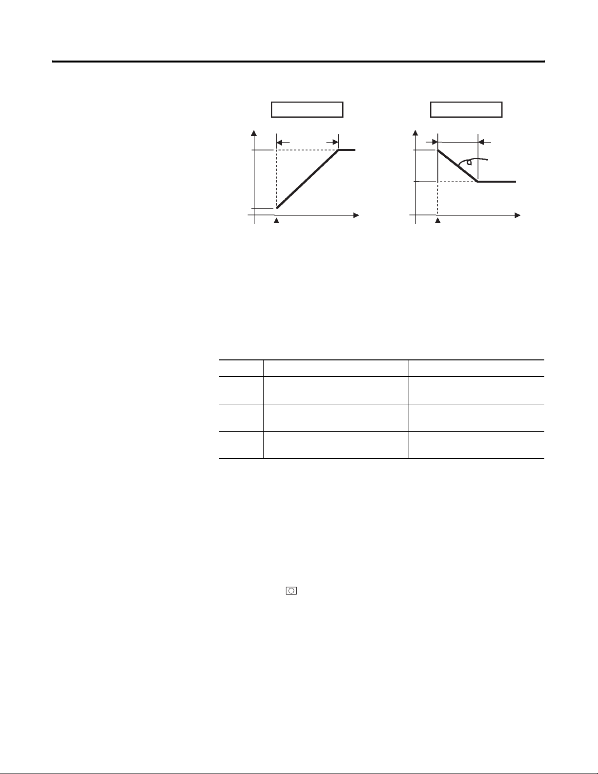
4-26 Parameter Adjustments and Application Considerations
Figure 4.46
Set point
PV
PV < SP
SP SP
SP ramp
PV
Set point
Time
Power ON
PV > SP
SP ramp
Power ON
Restrictions During SP Ramp Operation
• Auto-tuning execution starts after the end of SP ramp.
• When control is stopped or an error occurs, the SP ramp function is
disabled.
Table 4.L Parameters
Symbol Parameters: Function Group Description
sl-h Set Point Upper Limit:
Initial Setting function group
For limiting SP setting
Same
change rate
Time
To Move to the Advanced Setting Function Group
sl-l Set Point Lower Limit:
For limiting SP setting
Initial Setting function group
sprt SP Ramp Set Value:
For limiting SP change rate
Advanced Setting function group
By default, the Advanced Setting function group is protected and you cannot
directly move to the function group. To move to this function group, you must
first cancel the protection applied by the Protect function group. See p. 4-28,
Using the Key Protect Function Group.
Example Operation Procedure
1. Press the and M keys simultaneously for at least 3 seconds in the
Operation function group. The key pressing time can be changed in the
Protect function group move time, which is in the Advanced Setting
function group.
Publication 900-UM001C-EN-E - January 2004
Page 97
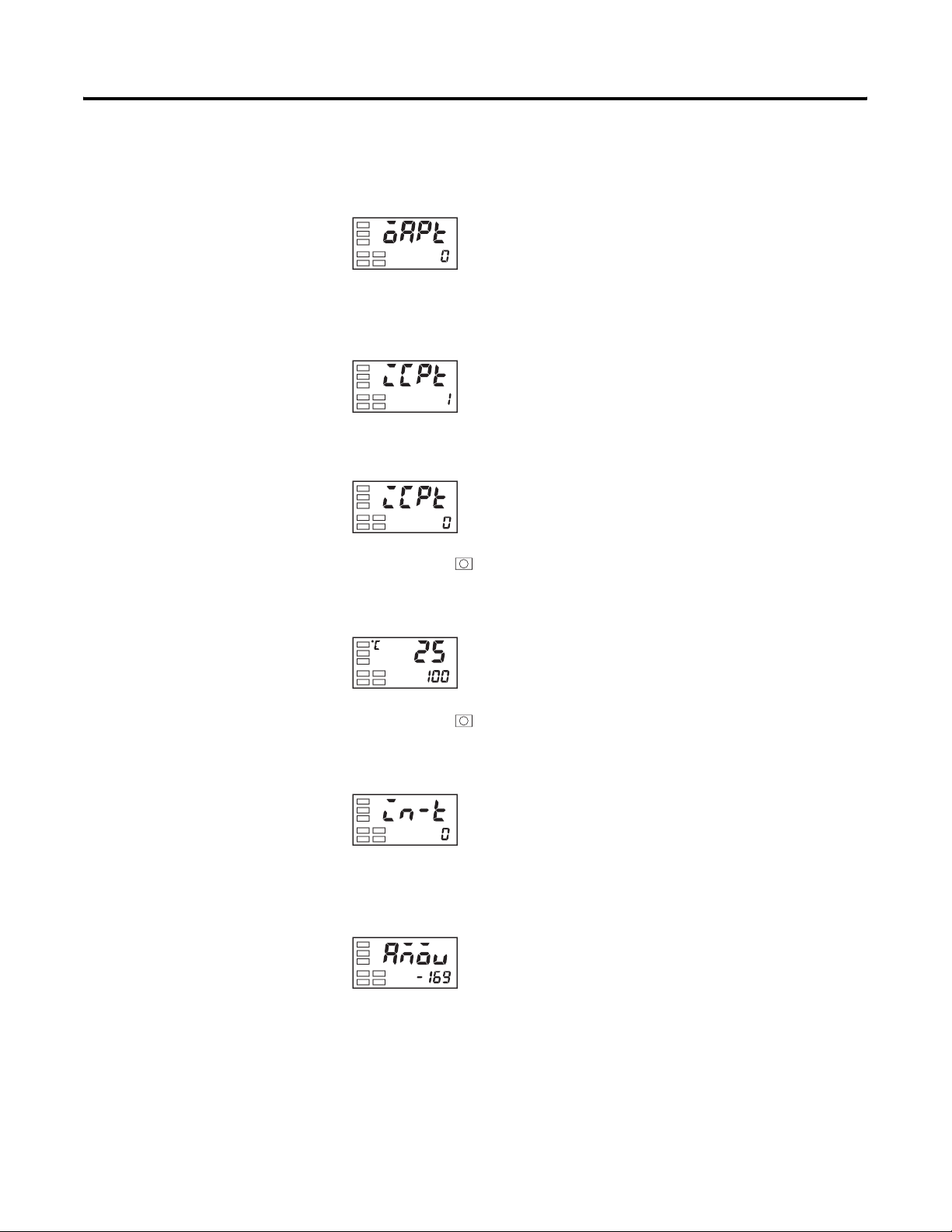
Parameter Adjustments and Application Considerations 4-27
2. The controller moves to the Protect function group, and
Operation/Adjustment Protection is displayed.
Figure 4.47
Protect function group
Operation/
adjustment
protection
3. Press the M key once to move to Initial Setting/Communications
Protection.
Figure 4.48
Initial setting/
communications
protection”
4. Configure the value to 0.
Figure 4.49
5. Press the and M keys simultaneously to return to the Operation
function group.
Figure 4.50
Operation function group
PV/SP
6. Press the key for at least 3 seconds to move to the Initial Setting
function group from the Operation function group.
Figure 4.51
Initial Setting function group
Input type
7. Select the Move to Advanced Setting Function Group parameter by
pressing the M key.
Figure 4.52
Move to Advanced
setting function
group
Publication 900-UM001C-EN-E - January 2004
Page 98
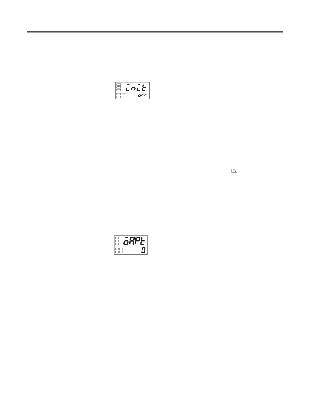
4-28 Parameter Adjustments and Application Considerations
8. Press the D key to enter the password (–169), and either press the M
key or leave the setting for at least 2 seconds to move to the Advanced
Setting function group from the Initial Setting function group.
Figure 4.53
Advanced setting
function group
Using the Key Protect Function Group
Key Protect
The Key Protect feature prevents some keypad functions from working. Three
different modes of protection are provided: Operation/Adjustment
protection, Initial Setting/Communications protection, and Configuration
Change protection.
To move to the Key Protect function group, press the and M keys
simultaneously for at least 3 seconds.
The Key Protect function group setting restricts the type of parameters that
can be used.
Operation/Adjustment Protection
Figure 4.54
Protect function group
The following table shows the relationship between configured/set values and
the level of protection.
Publication 900-UM001C-EN-E - January 2004
When this parameter is configured to 0, parameters are not protected. Note:
The default is 0.
Page 99
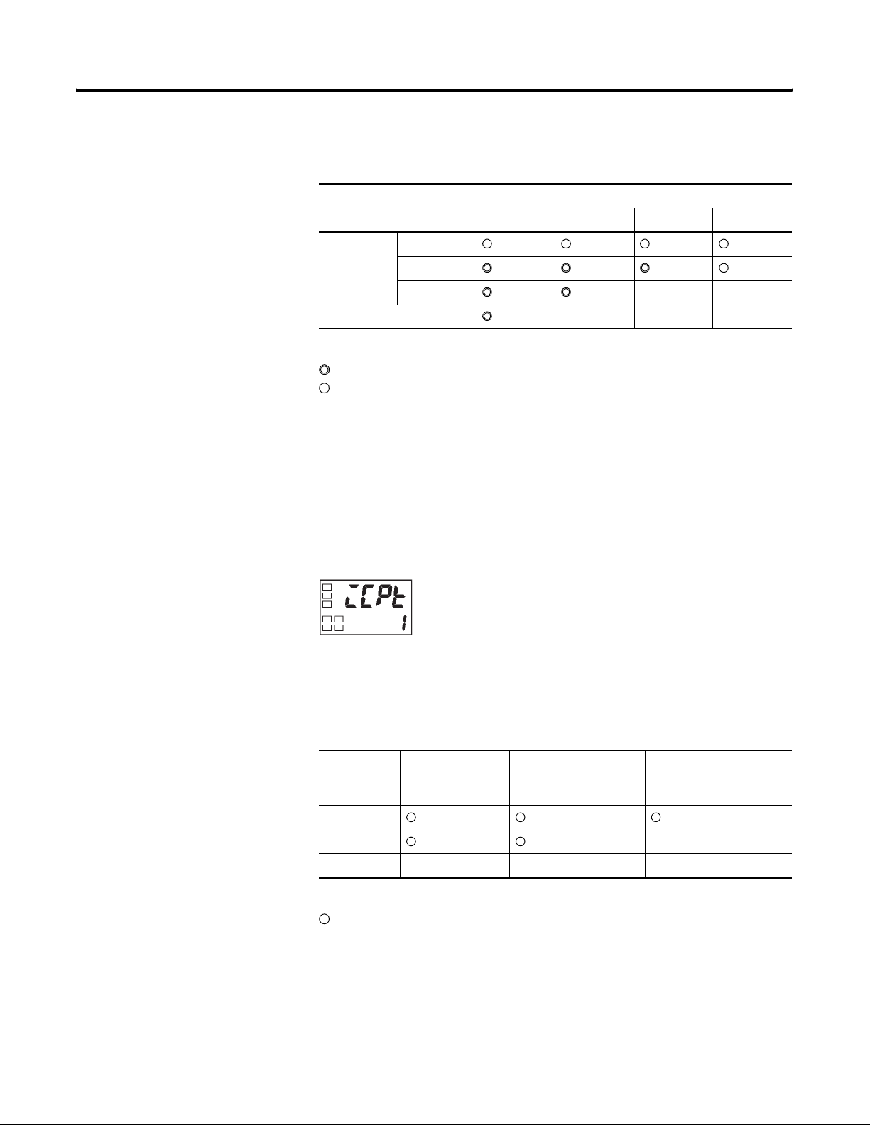
Parameter Adjustments and Application Considerations 4-29
Table 4.M Operation Protection
Function Group Configured/Set Value
0 ➊ 123
Operation
function
group
PV
PV/SP
Other X X
Adjustment function group X X X
Level of Protection:
Can be displayed and changed.
Can be displayed.
X Cannot be displayed and moving to other function groups is not possible.
➊ Default
Initial Setting/Communications Protection
This portion of the Key Protect function group restricts movement by keypad
operation to the Initial Setting function group, Communications Setting
function group, and Advanced Setting function group (see Table 4.N).
Figure 4.55
Note: The default is 1.
Table 4.N Initial Setting/Communications Protection
Configured
Value
0
1 ➋ X
2X X X
Level of Protection:
Moving to other function groups is possible.
X Moving to other function groups not possible.
➋ Default
Initial Setting
Function Group
Communications
Setting Function
Group
Advanced Setting
Function Group
Publication 900-UM001C-EN-E - January 2004
Page 100
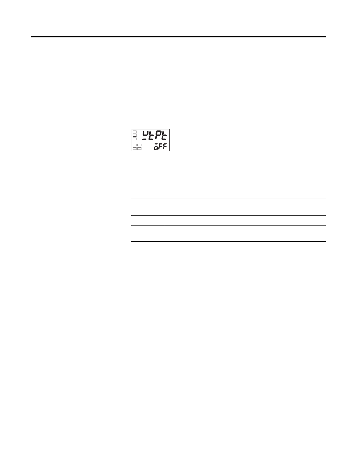
4-30 Parameter Adjustments and Application Considerations
Configuration Change Protection
This portion of the Protect function group protects setup from being changed
by
operating the keys on the front panel (see Table 4.O).
Figure 4.56
Note: The default is OFF.
Table 4.O Configuration Change Protection
Configured
Value
OFF ➊ Setup can be changed by key operation.
ON Setup cannot be changed by key operation. (The Protect function group
➊ Default
Description
can be changed.)
Publication 900-UM001C-EN-E - January 2004
 Loading...