

Page 1

Installation Instructions
Dual Probe Holder
Cat. No. EK-29000-DPH01
This document provides information to install the Allen-Bradley Dual Probe Holder. The
Dual Probe Holder is designed to combine a displacement transducer and an Allen-Bradley
9000 series sensor (velocity or accelerometer) into a single housing. The Dual Probe Holder
can be used in conjunction with the Allen-Bradley XM
provide shaft relative, case absolute, and shaft absolute measurements.
Note that the Dual Probe Holder is also functional with either one of the two sensors
installed.
For more information on the XM-121 Absolute Shaft module, refer to the XM-121 Absolute
Shaft User Guide (publication GMSI10-UM014x-EN-E). Refer to the specific sensor manual
for recommended wiring requirements and specifications for that sensor.
For information about See page
Important User Information 2
About the Dual Probe Holder 3
Installing the Dual Probe Holder 6
Replacing the Sensors in Dual Probe Holder 10
Specifications 13
®
-121 Absolute Shaft module to
Publication GMSI10-UM028A-EN-E - November 2007
Page 2
2 Dual Probe Holder
Important User Information
Solid state equipment has operational characteristics differing from those of electromechanical
equipment. Safety Guidelines for the Application, Installation and Maintenance of Solid State Controls
(Publication SGI-1.1 available from your local Rockwell Automation sales office or online at
http:///literature.rockwellautomation.com) describes some important differences between solid state
equipment and hard-wired electromechanical devices. Because of this difference, and also because of the
wide variety of uses for solid state equipment, all persons responsible for applying this equipment must
satisfy themselves that each intended application of this equipment is acceptable.
In no event will Rockwell Automation, Inc. be responsible or liable for indirect or consequential damages
resulting from the use or application of this equipment.
The examples and diagrams in this manual are included solely for illustrative purposes. Because of the many
variables and requirements associated with any particular installation, Rockwell Automation, Inc. cannot
assume responsibility or liability for actual use based on the examples and diagrams.
No patent liability is assumed by Rockwell Automation, Inc. with respect to use of information, circuits,
equipment, or software described in this manual.
Reproduction of the contents of this manual, in whole or in part, without written permission of Rockwell
Automation, Inc. is prohibited.
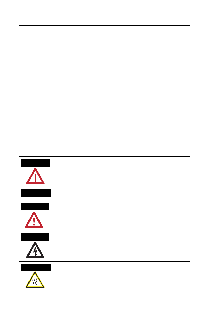
Throughout this manual, when necessary we use notes to make you aware of safety considerations.
WARNING
Identifies information about practices or circumstances that can cause an explosion in a
hazardous environment, which may lead to personal injury or death, property damage,
or economic loss.
IMPORTANT
ATTENTION
SHOCK HAZARD
BURN HAZARD
Identifies information that is critical for successful application and understanding of the
product.
Identifies information about practices or circumstances that can lead to personal injury
or death, property damage, or economic loss. Attentions help you identify a hazard,
avoid a hazard, and recognize the consequences.
Labels may be located on or inside the equipment, for example, a drive or motor, to alert
people that dangerous voltage may be present.
Labels may be located on or inside the equipment, for example, a drive or motor, to alert
people that surfaces may be dangerous temperatures.
Publication GMSI10-UM028A-EN-E - November 2007
Page 3
Dual Probe Holder 3
About the Dual Probe Holder
The Dual Probe Holder provides a single housing for a non-contact eddy current probe and
an Allen-Bradley 9000 series sensor. The Dual Probe Holder allows the eddy current probe
and the 9000 sensor to be installed at the same point on the same bearing half. The Dual
Probe Holder mounts on the machine casing and the installed sensors connect to a
monitoring system such as the XM-121 Absolute Shaft module.
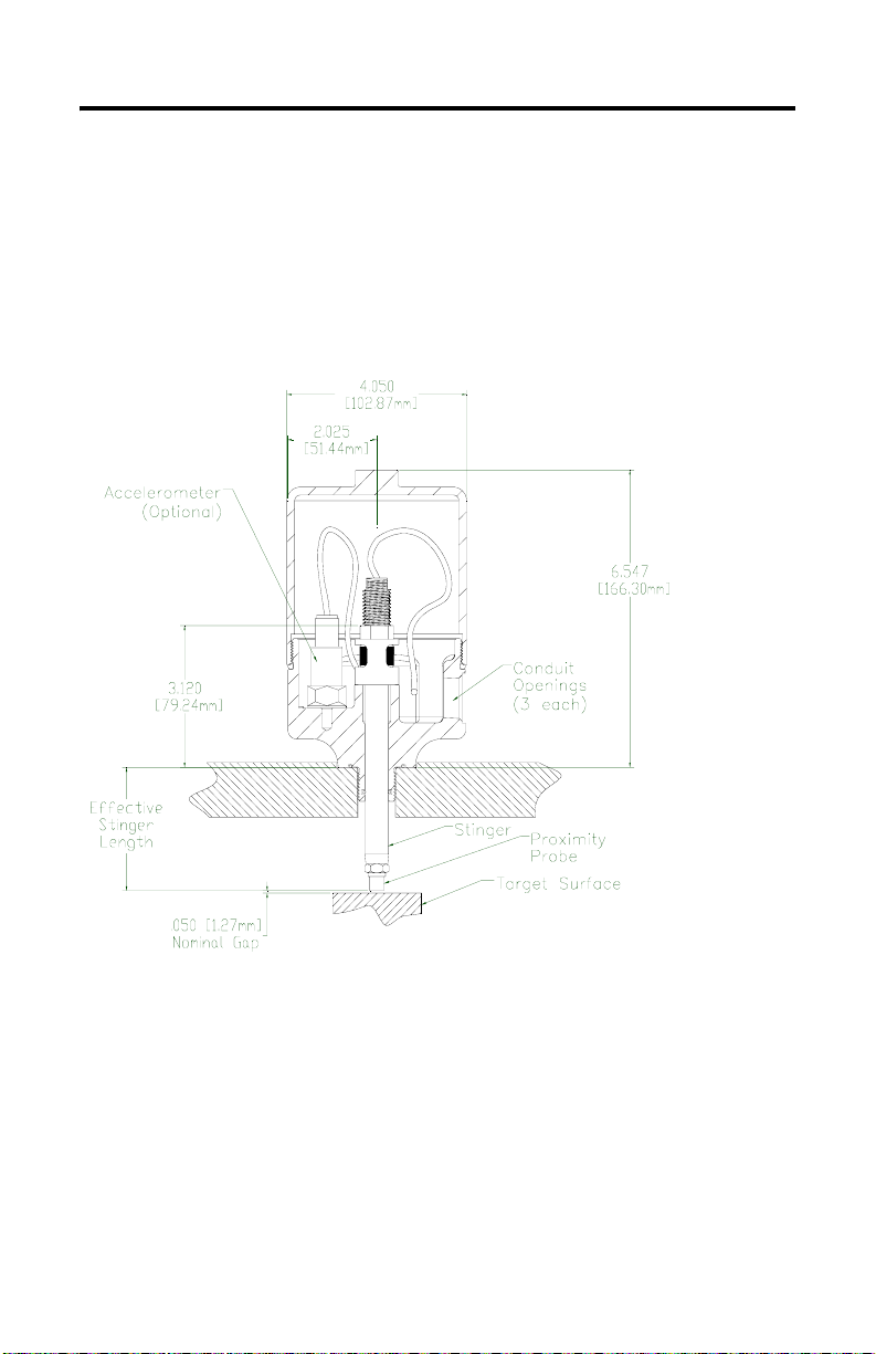
Figure 1 Dual Probe Holder Internal Side View
The Dual Probe Holder consists of a base that threads into the machine case, three conduit
ports for wiring connections, a stinger of optional length, o-rings, an eddy current probe, a
case vibration sensor, a jam nut, adjusting cage and knurling adjusting knob to secure the
stinger to the base to maintain the probe-to-shaft gap. And the Dual Probe Holder cover
screws onto the base of the holder. See
The location in which the probe and holder is installed determines which stinger you use.
Refer to Dual Probe Holder Ordering Information on page 5.
Figure 2 on page 4.
Publication GMSI10-UM028A-EN-E - November 2007
Page 4
4 Dual Probe Holder
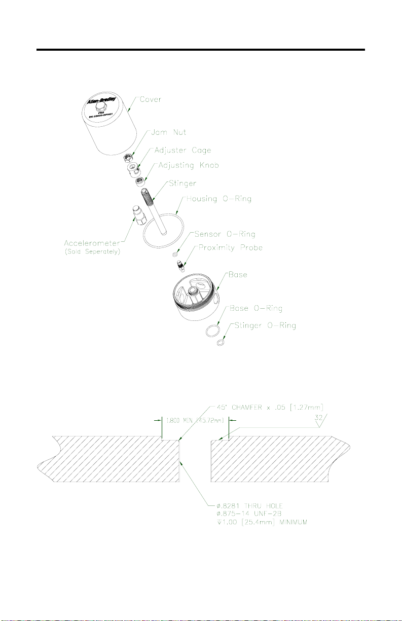
Figure 2 Dual Probe Holder Exploded View
Figure 3 Mounting Requirements
Publication GMSI10-UM028A-EN-E - November 2007
Page 5

Dual Probe Holder 5
Dual Probe Holder Ordering Information
The following items are options for the Rockwell Automation Dual Probe Holder, Cat. No.
EK-29000-DPH01.
Table 1 Dual Probe Holder Items
Rockwell Automation Cat. No. Description
48772-0200 Stainless steel stinger, 2.00 to 3.00 in. (5.1 to 7.6 cm) probe
48772-0300 Stainless steel stinger, 3.00 to 4.00 in. (7.6 to 10.2 cm) probe
48772-0400 Stainless steel stinger, 4.00 to 5.00 in. (7.6 to 12.7 cm) probe
48772-0500 Stainless steel stinger, 5.00 to 6.00 in. (12.7 to 15.2 cm) probe
48772-0600 Stainless steel stinger, 6.00 to 7.00 in. (15.2 to 17.8 cm) probe
48772-0700 Stainless steel stinger, 7.00 to 8.00 in. (17.8 to 20.3 cm) probe
48772-0800* Stainless steel stinger, 8.00 to 9.00 in. (20.3 to 22.9 cm) probe
48772-0900* Stainless steel stinger, 9.00 to 10.00 in. (22.9 to 25.4 cm) probe
48772-1000* Stainless steel stinger, 10.00 to 11.00 in. (25.4 to 27.9 cm) probe
48772-1100* Stainless steel stinger, 11.00 to 12.00 in. (27.9 to 30.5 cm) probe
48772-1200* Stainless steel stinger, 12.00 to 13.00 in. (30.5 to 33.0 cm) probe
48772-1300* Stainless steel stinger, 13.00 to 14.00 in. (33.0 to 35.6 cm) probe
48772-1400* Stainless steel stinger, 14.00 to 15.00 in. (35.6 to 38.1 cm) probe
48772-9024* Stainless steel stinger, 24.00 in. (61.0 cm), for cut-to-length
* The unsupported length of stinger should not exceed 200 mm (8 in) per API 670.
adjustment range
adjustment range
adjustment range
adjustment range
adjustment range
adjustment range
adjustment range
adjustment range
adjustment range
adjustment range
adjustment range
adjustment range
adjustment range
applications. Probe end is not machined. The end must be machined
after stinger is cut to length.
Publication GMSI10-UM028A-EN-E - November 2007
Page 6

6 Dual Probe Holder
Table 1 Dual Probe Holder Items
Rockwell Automation Cat. No. Description
2109/30/05/1/05 2100 Series Reverse Mount 8 mm Probe with 0.5 m cable
2109/30/05/1/10 2100 Series Reverse Mount 8 mm Probe with 1.0 m cable
1442-PR-0812E0205N 1442 Series Reverse Mount 8 mm Probe with 0.5 m cable
1442-PR-0830M0505N 1442 Series Reverse Mount 8 mm Probe, Metric, with 0.5 cable
1442-PR-0812E0210N 1442 Series Reverse Mount 8 mm Probe with 1.0 m cable
1442-PR-0830M0510N 1442 Series Reverse Mount 8 mm Probe, Metric, with 1.0 cable
EK-43781I 9000A General Purpose Sensor
EK-43808I 9100VO Velocity Output Sensor
EK-43786I 9100CSA General Purpose Sensor
EK-43805I 9100T High Temperature Sensor
IMPORTANT
The Dual Probe Holder is also compatible with Bentley Nevada 3300 XL
(330105 and 330195) Series Probes.
Installing the Dual Probe Holder
This section describes the installation of the Dual Probe Holder.
Receiving, Unpacking, and Inspection
Unpack the Dual Probe Holder and inspect for possible damage during shipment. Report any
damages immediately to the local transportation agent and submit a copy to Rockwell
Automation.
Publication GMSI10-UM028A-EN-E - November 2007
Page 7

Dual Probe Holder 7
Installation
Follow the steps below to install the Dual Probe Holder. Refer to Figures on pages 3 and 4
for assistance. Make sure the machine is stopped before installing the Dual Probe Holder.
TIP
Follow API 670 requirements for surface finish and flatness, even for
non-API installations. If the surface is not properly prepared, it can reduce
the detection of higher frequencies.
Prepare Mounting Surface
1. Spot face the surface, then drill and tap a hole in the machine case where you want to
install the Dual Probe Holder.
Check Parts and (if necessary) Replace Housing and Stinger O-rings
2. Open the Dual Probe Housing cover and remove plastic bag containing adjusting
cage, adjusting knob, jam nut and o-rings.
3. Replace the installed housing and stinger Viton O-rings with Buna O-rings (supplied
in plastic bag) to meet low temperature operating conditions (see table below). If you
do not need to replace the o-rings, proceed to step 4.
placement of the o-rings.
The table below shows the required o-rings for the appropriate temperature operating
ranges.
Table 2 O-Ring Requirements
Temperature Operating Range Required O-ring
-10 to 400°F (-23 to 204°C) Viton O-ring (default)
-30 to 230°F (-34 to 110°C) Buna O-ring
Figure 3 on page 8 shows the
Publication GMSI10-UM028A-EN-E - November 2007
Page 8

8 Dual Probe Holder
Figure 3 Placement of O-Rings
Install Base on Machine
4. Install the appropriate base o-ring into the grove in the Dual Probe Holder base. See
Figure 3. Use Table 2 on page 7 to determine which o-ring to install.
5. Apply anti-seize compound to the threaded portion of the Dual Probe Holder base
and install the base into the machine casing. Tighten to 55 ft-lb (75 N-m) torque.
Install Reverse Mount Probe Stinger
6. Install the appropriate sensor o-ring onto the base of the threaded portion of the
probe. Use
7. Apply two drops of thread adhesive, such as Blue Loctite 242 (or greater), to the
probe threads.
8. Insert probe cable into the stinger and tighten probe to 66 in-lb (7.5 N-m).
Publication GMSI10-UM028A-EN-E - November 2007
Table 2 on page 7 to determine which o-ring to install.
Page 9

Dual Probe Holder 9
Install Stinger and Assemble Adjustment Mechanism
9. Screw the knurled adjusting knob down to the end of the threaded portion of the
stinger.
10. Apply a film of grease to the unthreaded surface of the stinger. Insert the stinger into
the base until the knurled adjusting knob contacts the base.
11. Install the adjusting cage and hand tighten.
12. Install the jam nut so flat portion of the stinger is above the jam nut.
Install 9000 Sensor
13. Install the 9000 series sensor into the base. Use stud or bolt (1/4-28 threads x 3/8
inch) and thread locking compound. Socket wrench can be used.
Connect Wiring
14. Connect the non-contact sensor and the 9000 series sensor to the monitoring system.
Wiring can pass through any of the three conduit holes. Refer to Wiring
Considerations on page 10. For specific wiring connections to the monitor, refer to
monitoring system’s manual.
Gap Non-Contact Sensor
15. Gap the probe. Refer to the eddy current probe manual for probe gap procedures and
specifications.
ATTENTION
16. Tighten jam nut. Use a wrench on flat portion of the stinger to ensure the stinger
does not move while tightening the jam nut. Tighten the jam nut to 35 ft-lb (48 N-m)
torque.
17. Verify gap voltage.
Do not scratch sensor tip or target surface.
Publication GMSI10-UM028A-EN-E - November 2007
Page 10

10 Dual Probe Holder
Install Cover
18. Apply a film of grease to the exposed surface of the housing o-ring (on base). Place
the Dual Probe Holder cover on the base, and hand tighten. Be sure to turn an
additional 1/2 turn to seat the enclosure seal.
Wiring Considerations
• There are three wiring holes machined in the base of the Dual Probe Holder to pass
cabling through. If a wiring hole is not needed, use a 3/4 inch plug to close the
opening. The plug will maintain a NEMA 4X rating for environmental protection.
• The field wiring must be enclosed in 3/4 inch conduit. The conduit must be sealed at
the cable entry to maintain a NEMA 4X rating.
• Protect cable ends from debris before pulling through conduit.
• Terminate the shielded wires at the monitor end to prevent ground loops.
Refer to the wiring requirements in the eddy current probe manual and the Allen-Bradley
9000 series sensor manual. In addition, refer to the monitor manual in which the sensors are
connected to for requirements specific to the monitor.
Replacing the Sensors in Dual Probe Holder
The Dual Probe Holder allows removing and installing of the sensors without disassembling
the machine. Follow the steps below to remove the sensors from the Dual Probe Holder.
Replacing Non-Contact Sensor
To remove probe from Dual Probe Holder
1. Remove the Dual Probe Holder cover.
2. Disconnect the probe lead from the extension cable.
3. Tighten the adjusting knob to hold the sensor away from the target.
4. Loosen jam nut and adjusting cage so stinger can be removed from the base. Be
careful not to move the knurled adjusting knob.
Publication GMSI10-UM028A-EN-E - November 2007
Page 11

Dual Probe Holder 11
5. Pull stinger out from base.
6. Unscrew probe and remove.
To install probe
1. Clean the threads of the stinger.
2. Install the appropriate sensor o-ring onto the base of the threaded portion of the
probe. Use Table 2 on page 7 to determine which o-ring to install.
3. Apply two drops of thread locking compound, such as Loctite 242 (or greater), to the
probe threads.
4. Insert probe cable into the stinger and tighten probe to 66 in-lb (7.5 N-m).
TIP
5. Apply a film of grease to the unthreaded surface of the stinger. Insert the stinger into
the base until the knurled adjusting knob contacts the base.
6. Install the adjusting cage and hand tighten.
To prevent the non-contact sensor from contacting the target
surface, it is advisable to rotate the knurled adjusting knob until it
bottoms out of threads.
7. Install the jam nut so the flat portion of the stinger is above the jam nut.
8. Connect the non-contact sensor to the monitoring system.
9. Gap the probe. Refer to the eddy current probe manual for probe gap procedures and
specifications.
ATTENTION
10. Tighten jam nut and verify gap voltage. Use a wrench on flat portion of the stinger to
ensure the stinger does not move while tightening the jam nut. Tighten the jam nut to
35 ft-lb (48 N-m) torque.
Do not scratch sensor tip or target surface.
Publication GMSI10-UM028A-EN-E - November 2007
Page 12

12 Dual Probe Holder
11. Apply a film of grease to the exposed surface of the housing o-ring (on base) if
needed. Place the Dual Probe Holder cover on the base, and hand tighten. Be sure to
turn an additional 1/2 turn to seat the enclosure seal.
Replacing Series 9000 Sensor
To remove 9000 sensor from Dual Probe Holder
1. Remove Dual Probe Holder cover.
2. Disconnect wiring leads.
3. Remove stud or bolt and remove sensor.
To install 9000 sensor
1. Clean housing threads.
2. Install 9000 sensor into the base. Use stud or bolt (1/4-28 threads x 3/8 inch) and
thread locking compound. Socket wrench can be used.
3. Apply a film of grease to the exposed surface of the housing o-ring (on base) if
needed. Place the Dual Probe Holder cover on the base, and hand tighten. Be sure to
turn an additional 1/2 turn to seat the enclosure seal.
Publication GMSI10-UM028A-EN-E - November 2007
Page 13

Specifications
Table 4 Dual Probe Holder Specifications
Product Feature Specification
Enclosure Dimensions See Figure 1 (page 3)
Housing Material 304 stainless steel
Adjusting Knob & Cage 303 stainless steel
Operating Temperature -51...177 °C (-60...351 °F)
Rating NEMA 4X
Weight 6.5 lb
Dual Probe Holder 13
Publication GMSI10-UM028A-EN-E - November 2007
Page 14

Rockwell Automation Support
Rockwell Automation provides technical information on the web to assist you in using our
products. At http://support.rockwellautomation.com, you can find technical manuals, a
knowledge base of FAQs, technical and application notes, sample code and links to software
service packs, and a MySupport feature that you can customize to make the best use of these
tools.
For an additional level of technical phone support for installation, configuration and
troubleshooting, we offer TechConnect Support programs. For more information, contact
your local distributor or Rockwell Automation representative, or visit
http://support.rockwellautomation.com.
Installation Assistance
If you experience a problem with a hardware module within the first 24 hours of installation,
please review the information that's contained in this manual. You can also contact a special
Customer Support number for initial help in getting your module up and running:
United States 1.440.646.3223
Outside United
States
Monday – Friday, 8am – 5pm EST
Please contact your local Rockwell Automation representative for any
technical support issues.
New Product Satisfaction Return
Rockwell tests all of our products to ensure that they are fully operational when shipped from
the manufacturing facility. However, if your product is not functioning and needs to be
returned:
United States Contact your distributor. You must provide a Customer Support case number
Outside United
States
Listen. Think. Solve, Allen-Bradley and XM are trademarks of Rockwell Automation, Inc.
Trademarks not belonging to Rockwell Automation are property of their respective companies.
(see phone number above to obtain one) to your distributor in order to
complete the return process.
Please contact your local Rockwell Automation representative for return
procedure.
Publication GMSI10-UM028A-EN-E - November 2007
Copyright © 2007 Rockwell Automation, Inc. All rights reserved. Printed in the U.S.A.
 Loading...