

Page 1
Quick Reference
Drives and Motion Accelerator Toolkit
Quick Start Summary
This quick start provides step by step instructions for
using the Drives and Motion Accelerator Toolkit to
help you design, install, operate, and maintain a drive
system. Included are selection tools, layout and wiring
drawings, and pre-configured logic and HMI files to
assist you in creating an Integrated Architecture™
solution that includes Allen-Bradley® servo drives and
PowerFlex® AC drives.
The instructions also show how the Drives and
Motion Accelerator Toolkit (DMAT) Wizard can
automate the tasks needed to build the files used in the
Integrated Architecture solution.
All the supporting files are included on the Drives and
Motion Accelerator Toolkit DVD, publication
IASIMP-SP017, including the DMAT Wizard. The
DVD provides drive selection tools; CAD drawings
for panel layout and wiring; basic status, control, and
diagnostic logic files; FactoryTalk® View ME and SE
faceplates, and more. For a copy of the DVD, contact
your local Allen-Bradley distributor or Rockwell
Automation® sales representative. With these tools and
the built-in best-practices design, the system designer
is free to focus on the design of their machine control
and not on design overhead tasks.
You can also download many of these same supporting files from the Rockwell Automation Integrated
Architecture Tools website, http://www.ab.com/go/iatools
on the Beyond Getting Started tab.
Page 2
2 Drives and Motion Accelerator Toolkit Quick Star t Summary
MOTOR
FIELD SIDE
DRIVE
PROTECTION
POWERFLEX 4
AC DRIVE
MOTOR_01
USER PROTECTED
XXXVAC SUPPLY
MAINS DISCONNECT
PROTECTION
XXAMPS
FILTERED POWER
Chapter 3
System Layout and Wiring
Chapter 1
Initial System Configuration Using the DMAT Wizard
Chapter 2
Bill of Materials Completion
Chapter 4
Logic Co nfiguratio n
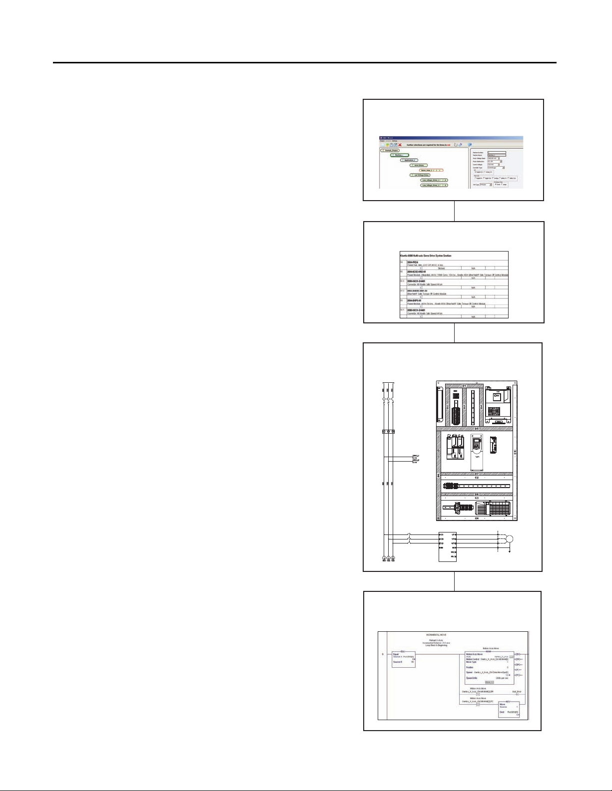
Quick Start Chapter Summary
Follow this path to complete your Drives and Motion
application.
Chapter 1 - Initial System Configuration Using the DMAT Wizard
In this chapter you use the Rockwell Automation DMAT
Wizard to create an initial bill of materials, assemble a system
drawing set, and create an RSLogix™ 5000 project file with a
preconfigured controller, network, drives and initial system
program logic. In addition, you are introduced to several
Rockwell Automation system configuration tools that provide
assistance in sizing your motor/drive combinations for a variety
of load, transmission, and application types.
Chapter 2 - Bill of Materials Completion
In this chapter you use Rockwell Automation ProposalWorks™
software to complete the drives and motion system bill of
materials that the DMAT Wizard created.
Chapter 3 - System Layout and Wiring
In this chapter you edit the set of layout and wiring drawings
from the DMAT drawing library that the DMAT Wizard
created.
Chapter 4 - Logic Configuration
In this chapter you edit the preconfigured logic file that the
DMAT Wizard created for your specific application.
Rockwell Automation Publication IASIMP-QS022B-EN-P - April 2012
Page 3
Drives and Motion Accelerator Toolkit Quick Start Summar y 3
Chapter 7
Motion System Application Guide
Servo Drive
755
00300
RESETTING
IDLE
(enabled)
START
RUNNING
STOPPING
STOP
STOPPED
(disabled)
CLEARING
ABORTED
ABORTING
RESET
ABORT
CLEAR
The machine can go from any state in the shaded box to STOPPING.
The machine can go from any state
in the solid box to ABORTING.
STARTING
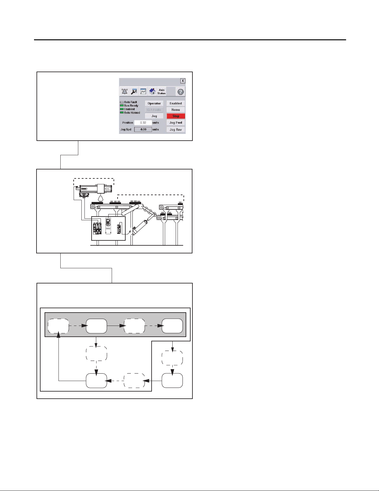
Chapter 7
System Application Guide
Chapter 5
FactoryTalk View ME Configuration
Chapter 6
System
Commissioning
Assembly
Packaging
Chapter 5 - FactoryTalk View ME Configuration
In this chapter you create the operator interface
application file for your system using FactoryTalk
View Studio software. The toolkit includes a
variety of preconfigured machine and device
faceplate displays providing status, control, and
diagnostics for your drives and motion system.
Chapter 6 - System Commissioning
In this chapter you download your Logix and
PanelView™ Plus applications, prepare and tune
your drive hardware, verify network
communications, and verify general operator/
program control.
Chapter 7 - System Application Guide
This chapter guides you through the preconfigured FactoryTalk View Machine Edition
application faceplates providing you with an
understanding of the status, control, and diagnostic
operation of the faceplate displays.
Rockwell Automation Publication IASIMP-QS022B-EN-P - April 2012
Page 4

4 Drives and Motion Accelerator Toolkit Quick Star t Summary
Machine
Module
Application
Module
Device
Module
PanelView Plus Terminal
Machine Faceplate
Controller Logic
HMI Application
Application
Status
Machine
Commands
Device
Commands
Device
Status
Operator
Commands
Machine Status
Device Faceplate
755
00300
X-Y Gantry
Diverter
Conveyor
Kinetix 6500
Drives
Kinetix 300
Drive
PowerFlex 753
Drive
Servo Motor Driven
Electric Cylinder
Induction Motor
X-Servo
Y-Se rvo
Assembly
Packaging
To assist you in device configuration, the Widg-O-matic machine application example is
referenced in the device configuration steps. Two servo drives are configured for the X-Y
gantry assembly section, one PowerFlex drive is configured for the conveyor, and one
Kinetix® 300 drive is configured for the packaging diverter.
Modularity Example - Machine/Application/Device Module Relationship
The machine module monitors the current state of the overall machine and based on the state and/or requests
from the HMI terminal, broadcasts out commands to both the application and device modules. The individual
modules perform a predefined task based on the command. Some of the commands may be ignored depending
on the module type.
Widg-O-matic Machine Application Example
Rockwell Automation Publication IASIMP-QS022B-EN-P - April 2012
Page 5

Drives and Motion Accelerator Toolkit Quick Start Summar y 5
Ch. 1 Example - Run the DMAT Wizard
Follow these steps to launch the DMAT Wizard and set up your wizard configuration.
1. Navigate to and select the
DMAT Wizard .exe file on the
Drives and Motion Accelerator
Toolkit DVD image.
The DMAT Wizard opens and a dialog box opens, explaining the general scope of the wizard.
2. Read the dialog box and click OK to continue wizard configuration.
The Open or Create a Project dialog box opens.
3. Click Create New to initiate a new project.
Another configuration information dialog box
opens, explaining machine, application, and drive
configuration.
4. Read configuration information dialog box and
click OK to continue.
Rockwell Automation Publication IASIMP-QS022B-EN-P - April 2012
Page 6

6 Drives and Motion Accelerator Toolkit Quick Star t Summary
Select and
delete
this drive
and cable.
Ch. 3 Example - Edit System Communication Drawings
1. Open the communication drawing for your application.
For the Widg-O-matic machine application example, the 060_120_Ethernet_Communication.dwg file is
opened.
2. Delete network devices not used in the project.
For the Widg-O-matic machine application example, one of the Kinetix 300 drives and associated cable is
deleted.
Ethernet Communication
Rockwell Automation Publication IASIMP-QS022B-EN-P - April 2012
Page 7

Drives and Motion Accelerator Toolkit Quick Start Summar y 7
Ch. 4 Example - Import and Configure Device and Application Status Logic
Follow these steps to add the device and application status information rungs to the R02_Monitor routine of
your machine program.
1. Expand the Tasks folder in your Controller Organizer.
2. Navigate to and open the R02_Monitor routine of your machine program.
For the Widg-O-matic application example, the R02_Monitor routine within the P01_WidgOmatic
program was opened.
3. Right-click Rung 13 of the R02_Monitor routine and select Import Rungs.
4. Navigate to the 4-Controller Logic folder
within the toolkit’s files folder and open the
01_Machine Logic folder.
Your personal computer’s harddrive path is
C:\Program Files\RA_Simplification\
DMAT\B-Files\4-Controller Logic.
Rockwell Automation Publication IASIMP-QS022B-EN-P - April 2012
Page 8

Ch. 5 Example - Restore and Open a Preconfigured HMI Application
IMPORTANT
Follow these steps to restore the preconfigured HMI file and open in FactoryTalk View Studio software.
1. Navigate to the HMI application files within the toolkit’s file folder and open either the
PanelView Plus 1000 or PanelView Plus 600 folder, based on the terminal size and faceplate requirements
of your application.
The Equipment Status faceplate is compatible with PanelView Plus 700 or larger terminals. To take full advantage of all
faceplates, choose the PanelView Plus 1000 folder.
Your personal computer’s harddrive path is C:\Program Files\RA_Simplification\DMAT\B-Files\
5-HMI\ME\HMI Applications.
For the Widg-O-matic machine application example, the PanelView Plus 1000 folder was selected.
PanelView Plus Terminal and Faceplates Compatibility
Application Folder PanelView Plus Terminals Supported Faceplates Displays
PVP600
PVP1000
(1) The PanelView Plus 1000 Machine, Alarm History, and Equipment Status faceplate displays are sized at 640x480 (VGA) resolution. If full-sized displays are desired, open
display, select all (objects), group, and resize group. Some text editing for new display size may also be required.
Allen-Bradley, FactoryTalk, Integrated Architecture, Kinetix, PanelView, ProposalWorks, PowerFlex, Rockwell Software, Rockwell Automation, and RSLogix are trademarks of
Rockwell Automation, Inc.
Trademarks not belonging to Rockwell Automation are property of their respective companies.
PanelView Plus 400
PanelView Plus 600
PanelView Plus 700
PanelView Plus 1000
PanelView Plus 1250
PanelView Plus 1500
(1)
(1)
Machine Startup Display
Machine State Diagram Display
All Device Displays
Alarm History Display
Machine Startup Display
Machine State Diagram Display
All Device Displays
Alarm History Display
Equipment Status Display
Publication IASIMP-QS022B-EN-P - April 2012
Supersedes Publication IASIMP-QR022A-EN-P - October 2010 Copyright © 2012 Rockwell Automation, Inc . All rights reserved. Printed in the U.S.A.
 Loading...