

Page 1
1. Allgemeine Hinweise
Der Baustein wurde nach den aktuellen Normen und
Vorschriften entwickelt und gefertigt.
Um die langfristige Funktion des Bausteins zu gewährleisten,
beachten Sie bitte die folgenden Hinweise: Ein Betrieb
außerhalb der Spezifikationen sowie Überspannungen und
/ -ströme bzw. Verpolung können zur Zerstörung oder zu
einer beeinträchtigten Funktionalität beim Betrieb des
Bausteins führen. Schützen Sie daher den Baustein durch
geeignete Maßnahmen (Überspannungsschutz, Leitungs führung, ESD-gerechte Handhabung).
Die Analogsignaltrenner MICRO
ANALOG Thermo dürfen nur
von qualifiziertem Fachpersonal installiert werden. Erst nach
der fachgerechten Installation darf das Gerät mit Hilfsenergie
versorgt werden. Während des Betriebs darf keine
Bereichsumschaltung vorgenommen werden. Die nationalen
Vorschriften (z. B. für Deutschland DIN VDE 0100) müssen
bei der Installation und Auswahl der Zuleitungen beachtet
werden. Eine zweipolige Trennvorrichtung zwischen Gerät
und Netz ist vorzusehen.
Bei der Bereichsumschaltung ist auf
Schutzmaßnahmen gegen elektrostatische
Entladung (ESD) zu achten.
2. Anwendung
Die Analogsignaltrenner 931H-T1C1D-DC dienen zur galvanischen Trennung und Wandlung von Thermo-spannungen in
Normsignale 0(4) ... 20 mA und 0 ... (5)10 V.
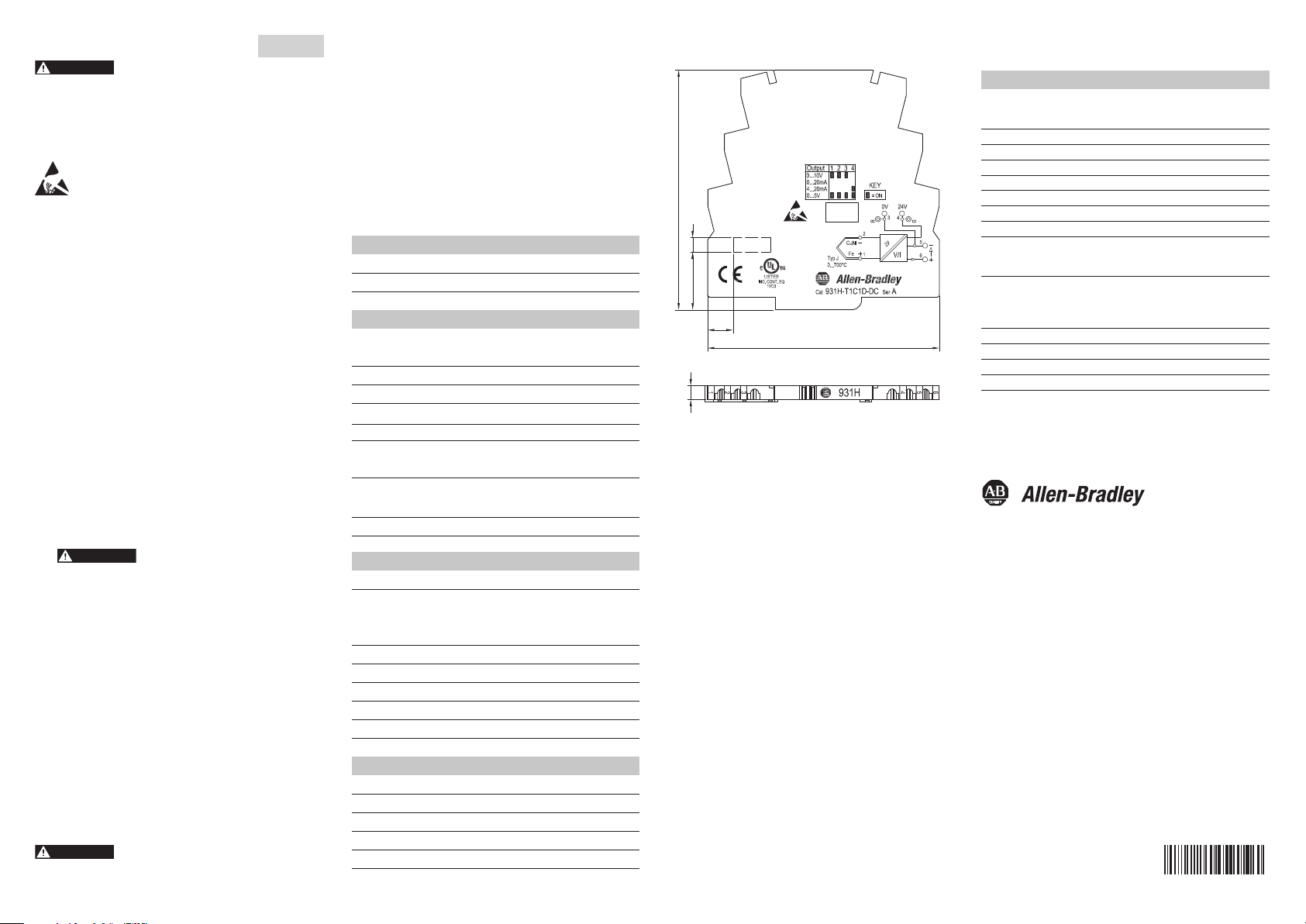
Das Ausgangssignal ist über DIP-Schalter kalibriert
umschaltbar (siehe Gehäuseaufdruck).
3. Konfigurierung
Stellen Sie die DIP-Schalter gemäß der Tabelle auf dem
Gehäuseaufdruck ein. (Werkseinstellung 0 ... 20 mA).
4. Montage, elektrischer Anschluss
Die Analogsignalwandler werden auf TS35 Normschienen
aufgerastet und seitlich durch geeignete Endwinkel fixiert.
Klemmenbelegung siehe Gehäuseaufdruck.
Anschlussquerschnitt max. 2,5 mm
2
.
Deutsch
Eingangsdaten
Eingang (fest)
Ausgangsdaten
Ausgang
(kalibriert umschaltbar)
Bürde
bei Ausgangsstrom
bei Ausgangsspannung
Genauigkeit (incl. Linearisierung und Kaltstellenkompensation)
Thermoelement
Typ J, 0...700 °C
Temperaturkoeffizient
Sprungantwortzeit
Allgemeine Daten
Spannungsversorgung
Stromtragfähigkeit der
Verbindung zwischen
Anschluss 3 und 5:
Leistungsaufnahme
Betriebstemperaturbereich
Lagertemperatur
Abmessungen L/H/B mm
Isolationskoordination nach DIN EN50178, 04/98
Bemessungsspannung
Prüfspannung
Überspannungskategorie
Verschmutzungsgrad
* Tu 20 °C
Thermoelemente gem. EN 60584-1
Typ J, 0...700 °C
0...10V / 4...20mA / 0…5V
0...20mA (Werkseinstellung)
< 400 Ohm @ Versorgung ≥ 24 Vdc
> 10 kOhm
< 0,7 % vom Messbereich
< 250 ppm/K vom Messbereich
< 0,7 sek
24 Vdc (±10%)
100 mA
ca. 0,6 W
0...+55 °C
-25 °C...+85 °C
88 / 98 / 6,1
100 V
500 V
III
2
6. Technische Daten*
ACHTUNGACHTUNGACHTUNGACHTUNG
Caractéristiques d‘entrée
Entrées (fixe)
Caractéristiques de sortie
Sorties
(à calibre commutable)
Charge
pour courant de sortie
pour tension de sortie
Précision (avec linéarisation et compensation de soudure froide)
Thermocouple
Type J, 0...700 °C
Coefficient de temp.
Fréquence limite
Caractéristiques générales
Tension d'alimentation
Courant admissible de
la liaison entre les
bornes 3 et 5:
Puissance consommée
Plage de température de
fonctionnement
Température de stockage
Dimensions L/H/B mm
Coordination des isolements selon DIN EN50178, 04/98
Tension nominale
Tension d'essai
Classe de surtension
Degré de pollution
* Ta 20 °C
Thermocouples selon EN 60584-1
Type J, 0...700 °C
0...10V / 4...20mA / 0…5V
0...20mA (réglage d'usine)
< 400 Ohm @ Alimentation ≥ 24 Vdc
> 10 kOhm
< 0,7 % de la plage de mesure
< 250 ppm/K
de la plage de mesure
< 0,7 s
24 Vdc (±10%)
100 mA
env. 0,6 W
0...+55 °C
-25 °C...+85 °C
88 / 98 / 6,1
100 V
500 V
III
2
1. Remarques générales
Ce module a été développé et fabriqué en respect des
normes et prescriptions en vigueur. Afin d’assurer le bon
fonctionnement du module sur le long terme, veuillez
respecter les instructions suivantes: Exploiter le module en
dehors des spécifications, le soumettre à des surtensions,
des surintensités ou une inversion de polarité peut conduire à
la destruction de celui-ci ou entraver les fonctionnalités
lorsque le module est utilisé. Veuillez par conséquent prendre
toute mesure nécessaire pour protéger le module (protection
contre les surtensions, câblage, manipulation évitant les
pointes de tension).
Les séparateurs de signaux analogiques MICRO
ANALOG
Thermo ne doivent être installés que par du personnel
qualifié. L’alimentation électrique de l’appareil ne doit être
réalisée qu’après une installation conforme aux prescriptions.
Ne pas changer de plage pendant le fonctionnement.
Respecter les directives nationales en vigueur pour
l’installation et la sélection des câbles. Un dispositif de
coupure agissant sur deux pôles doit être installé entre
l’appareil et l’alimentation.
Lors de la sélection des plages, veuillez prendre
les mesures nécessaires de protection contre les
décharges électrostatiques.
2. Utilisation
Les séparateurs analogiques de signal 931H-T1C1D-DC
servent à la séparation galvanique et à la conversion des
tensions de thermocouple en signaux normalisés 0(4) à 20
mA et 0 à (5)10 V.
Le calibre des signaux d’entrée et de sortie est commutable
par commutateurs DIP
(voir indication sur le boîtier).
3. Configuration
Régler les commutateurs DIP suivant le tableau imprimé sur
le boîtier (réglage usine 0 ... 20 mA).
4. Montage, raccordement électrique
Les séparateurs sont encliquetés sur des rails de norme
TS35 et fixés latéralement à l’aide d’une équerre adaptée.
Brochage voir boîtier.
Section max. de raccordement 2.5 mm
2
.
Français
6. Caractéristiques techniques*
ATTENTIONATTENTION
Page 2
931H-T1C1D-DC
90
5,2
87
9,5
21,6 5,5
Ty pe
Order No.
Qty.
Plug-In Jumper
Querverbindung
Connexion transvrsale
Plug-In Jumper, 2-pole, red 1492-CJLJ6-2-R 60
Plug-In Jumper, 3-pole, red 1492-CJLJ6-3-R 60
Plug-In Jumper, 10-pole, red 1492-CJLJ6-10-R 20
Plug-In Jumper, 41-pole, red 1492-CJLJ6-41-R 10
Plug-In Jumper, 2-pole, blue 1492-CJLJ6-2-B 60
Plug-In Jumper, 3-pole, blue 1492-CJLJ6-3-B 60
Plug-In Jumper, 10-pole, blue 1492-CJLJ6-10-B 20
Markers
Verbindermarkierer
Repérage de blocs de jonction 1492-M6X10 200
Power Supply
24 V DC Output
15 W 1606-XLP15E
30 W 1606-XLP30E
50 W 1606-XLP50E
100 W 1606-XLP100E
120 W (5 A) 1606-XLE120E
Accessories / Zubehör / Accessoires
Thermocouple, Type J
931H-T1C1D-DC
Installation Instructions
Beipackinformation
Notice d’utilisation
DIR 10000043422
(Version 00)
10000043422
1. General instructions
• Disconnect power prior to installation
• Installation only by Qualified personnel
• Follow all applicable local and national electrical codes
During range selection, appropriate safety
measures against electrostatic discharge (ESD)
are to be considered.
2. Application
The Thermocouple, Type J 931H-T1C1D-DC is designed to
galvanically isolate and convert thermoelectric voltages into
standard signals 0(4) ...20 mA and 0 ... (5)10 V.
(see enclosure).
3. Configuration
Set the DIP switches according to the table printed on
the enclosure (factory setting 0 ... 20 mA).
4. Mounting, electrical connection
The signal conditioners are mounted on standard TS35
rails and fixed in position by a suitable end bracket.
For terminal assignments see enclosure.
Wire cross-section max. 2.5 mm
2
.
ATEX - Approval Rockwell Automation
UL DEMKO 09 ATEX 147279X 1201South Second Street
T II 3G Ex nAnL IIC T4 Milwaukee, Wi 53204
U.S.A.
UL Class 1, Division 2 Markings
for selected Signal Conditioners
A. “This equipment is suitable for use in Class I, Division 2,
Groups A, B, C and D hazardous locations or nonhazardous locations only or the equivalent.”
B. “WARNING: EXPLOSION HAZARD - Substitution of
components may impair suitability for use in Class I,
Division 2 environments.”
C. “WARNING: EXPLOSION HAZARD - The area must be
known to be nonhazardous before servicing/replacing
the unit and before installing or removing I/O wiring.”
D. “WARNING: EXPLOSION HAZARD - Do Not disconnect
equipment unless power has been disconnected and
the area is known to be nonhazardous.”
FOR INSTALLATION IN CLASS I, ZONE 2 LOCATIONS:
E. This equipment is to be installed into suitable enclosure,
providing a degree of protection not less than IP 54 in
accordance with IEC 60529 unless the apparatus is
intended to be afforded an equivalent degree of protection by location.
Do not disconnect while circuit is live unless area is known
to be non hazardous. The enclosure for the installation of
English
Input data
Input (fixed)
Output data
Output
(selectable)
Load resistance
Output current
Output voltage
Accuracy
(incl. linearization and cold junction compensation)
Thermo Type
Typ J, 0...700 °C
Temperature coefficent
Response time
General data
Supply voltage
Current carrying capacity
of the connection between
connections 3 and 5:
Power consumption
Operating temperature
Storage temperature
Dimensions L/H/W mm
Coordination of insulation acc. to DIN EN50178, 04/98
Rated voltage
Rated surge voltage
Overvoltage category
Contamination class
* Tu 20 °C
Thermocouple as in EN 60584-1
Type J, 0...700 °C
0...10V / 4...20mA
/ 0…5V
0...20mA (factory setting)
< 400 Ohm @ power supply ≥ 24 Vdc
> 10 kOhm
< 0.7 % of selected range
< 250 ppm/K of selected range
< 0.7 sek
24 Vdc (±10%)
100 mA
approx. 0.6 W
0...+55 °C
-25 °C...+85 °C
88 / 98 / 6.1
100 V
500 V
III
2
6. Technical data*
WARNINGWARNINGWARNINGWARNING
WARNINGWARNINGWARNINGWARNING
the apparatus shall have a protection not less than IP54 in
accordance with IEC 60529.
"This device is to be installed in area of a pollution degree
of not more than pollution degree 2, as defined in IEC
60664-1. Alternatively the device may be installed into
enclosure providing a degree of protection not less than
IP 64 in accordance with IEC 60529."
“Connectors are not to be separated when they are
energized.”
T
amb
0 °C to 55 °C
WARNINGWARNINGWARNINGWARNING
 Loading...