

Page 1
(catalog no. 9220-KTCT)
Use this document to install and use the 9220-KTCT communication
interface card. This card lets a 16-bit ISA- or 32-bit EISA-compatible
computer communicate on a ControlNet
To install the card, read See page
important user information 2
configuring the card 3
installing the card inside the computer 13
running the installation check utility 15
connecting the card to a ControlNet network
For this reference information See page
interpreting the status indicators on the card 22
environmental specifications 23
If you are connecting a 9220-KTCT card directly to a ControlNet
network you should also refer to this documentation:
link.
17
ControlNet Coax Tap
Installation Instructions
publication 1786-5.7
,
ControlNet Cable
System Planning and
Installation Manual,
publication 1786-6.2.1
9220-5.1 — November 1996
Page 2

ControlNet ISA/EISA Bus Tool Installation Instructions2
Important User Information
Because of the variety of uses for the products described in this publication,
those responsible for the application and use of this control equipment must
satisfy themselves that all necessary steps have been taken to assure that each
application and use meets all performance and safety requirements, including
any applicable laws, regulations, codes and standards.
The illustrations, charts, sample programs and layout examples shown in this
guide are intended solely for purposes of example. Since there are many
variables and requirements associated with any particular installation,
Allen-Bradley does not assume responsibility or liability (to include intellectual
property liability) for actual use based upon the examples shown in this
publication.
Allen-Bradley publication SGI-1.1, Safety Guidelines for the Application,
Installation, and Maintenance of Solid State Control (available from your local
Allen-Bradley office), describes some important dif
equipment and electromechanical devices that should be taken into consideration
when applying products such as those described in this publication.
Reproduction of the contents of this copyrighted publication, in whole or in part,
without written permission of Allen-Bradley Company, Inc., is prohibited.
ferences between solid-state
Throughout this document we use notes to make you aware of safety
considerations:
ATTENTION: Identifies information about practices or
circumstances that can lead to personal injury or death,
!
Attention statements help you to:
property damage or economic loss.
• identify a hazard
• avoid the hazard
• recognize the consequences
Important:
9220-5.1
Identifies information that is critical for successful application and
understanding of the product.
— November 1996
Page 3

ControlNet ISA/EISA Bus Tool Installation Instructions 3
Configuring the 9220-KTCT
Before installing the 9220-KTCT inside your computer, you must
determine if you need to change the card’s default physical addresses.
This address
base memory address
base I/O space address the host processor’s I/O map—so the card’s I/O devices can
À
You
memory and base I/O space addresses.
À
can have as many as four 9220-KTCT cards in one computer as long as each has dif
Specifies
ROM I/O expansion area of the host processor’s system
memory—so the card and the host computer can exchange
data through the dual-port interface.
receive commands from the host computer.
ferent base
To reset these addresses, you set switches on the card. The 9220-KTCT
comes factory-set with these addresses:
Address type Address setting (hex)
base memory
base I/O space memory 220
D000:0000
Important: When deciding which addresses to use, remember that:
• each card in your computer must have unique addresses
If another card in the host computer is using one or both of the
factory-set addresses, you must change a card’s switch settings to
an available address. If there is a conflict, the system will not
operate properly.
• you cannot mix 8-bit and 16-bit cards in a 64K segment boundary
That is, a 9220-KTCT and 1784-KT/B cannot be placed in the same
segment range of D000:0000 – DFFF:0000 or C000:0000 –
CFFF:0000. The 8-bit card may not work in this setup.
The two cards, 9220-KTCT (16-bit) and KT/B (8-bit), can be placed
with one in the C000:0000 – CFFF:0000 range and one in the
D000:0000 – DFFF:0000 range.
• the card must have a unique base memory address
If you are Go to page
changing the base memory address on the card 4
changing the base I/O space address on the card 7
using the factory-set addresses 13
9220-5.1
— November 1996
Page 4
ControlNet ISA/EISA Bus Tool Installation Instructions4
Selecting the Base Memory Address Location
The host computer and the 9220-KTCT card exchange data via a
dual-port interface. The dual-port interface is 16 Kbytes long and it
begins at the specified base memory address location.
The 9220-KTCT card comes set to memory address D000:0000. If this
memory address has been allocated to other interface cards or expansion
memory cards you have installed in your computer system, change the
9220-KTCT’s switch settings to an available memory address.
To select a new base memory address:
1. Pick an available memory address for the card, using the ROM I/O
adapters area of your host computer’s memory and Worksheet A,
on page 5. Be sure to choose a block that is 16 Kbytes long.
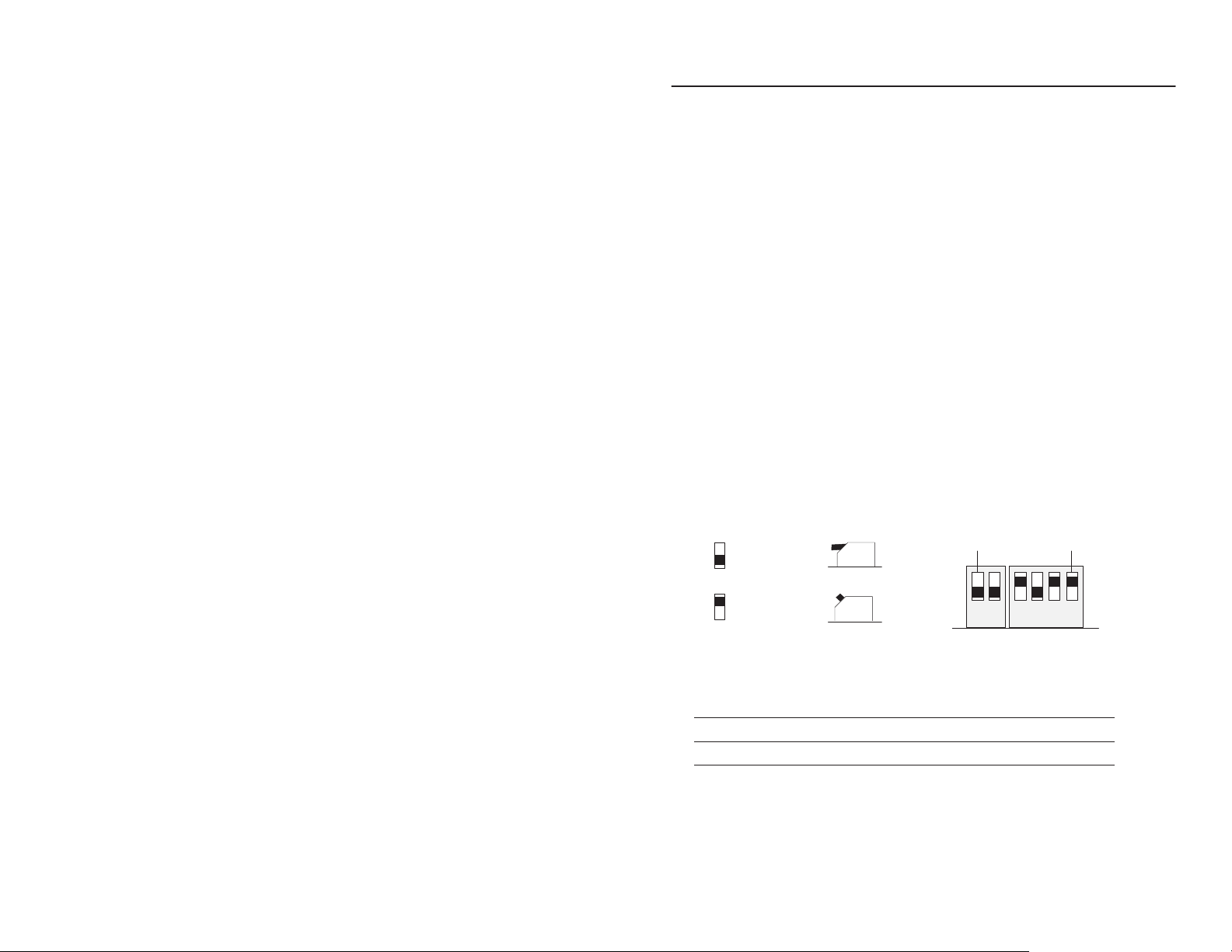
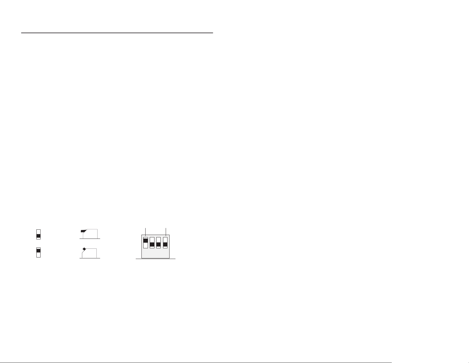
2. Determine the proper switch settings for this new address, using
Worksheet B, on page 6.
3. Set the switches on the 9220-KTCT to the new address, using the
guide below:
Front View
up (1)
12 1234
down (0)
down (0)
up (1)
Side ViewFront View
S2 S1
4. Fill in Worksheet C, on page 6.
If you are Go to page
5.
changing the base I/O space address on the card
using the factory-set base I/O space address 13
9220-5.1
— November 1996
MSBLSB
7
Page 5
ControlNet ISA/EISA Bus Tool Installation Instructions 5
9220-KTCT
memory
W
orksheet
Base
Base Memory Address
(hex)
0000:0000–07000:FFFF
8000:0000–09000:FFFF
A000:0000– V
A400:0000–
A800:0000–
AC00:0000–
B000:0000–
B400:0000–
B800:0000–
BC00:0000–
C000:0000–
C400:0000–
C800:0000–
CC00:0000–
D000:0000–
D400:0000–
D800:0000–
DC00:0000–
E000:0000–F000:FFFF
10000:0000–FF000:FFFF
A
memory allocation worksheet
Host Computer Assignments Your System
512K Read/Write Memory on
System Board
128K Read/W
Expansion in I/O Channel
Expansion Card Area
(area available for
9220-KTCT
128K ROM Reserved on System
Board
I/O Channel Expansion Memory
(inaccessible to the 9220-KTCT)
ideo Buf
rite Memory
fer
memory addresses)
addresses)
9220-5.1
— November 1996
Page 6
ControlNet ISA/EISA Bus Tool Installation Instructions6
W
orksheet B
9220-KTCT
switch settings
Base Memory Addr (hex)
C000:0000
C400:0000
C800:0000
CC00:0000
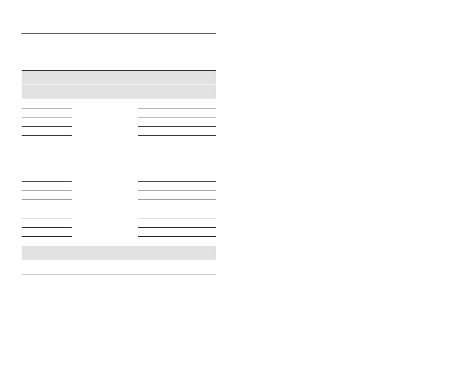
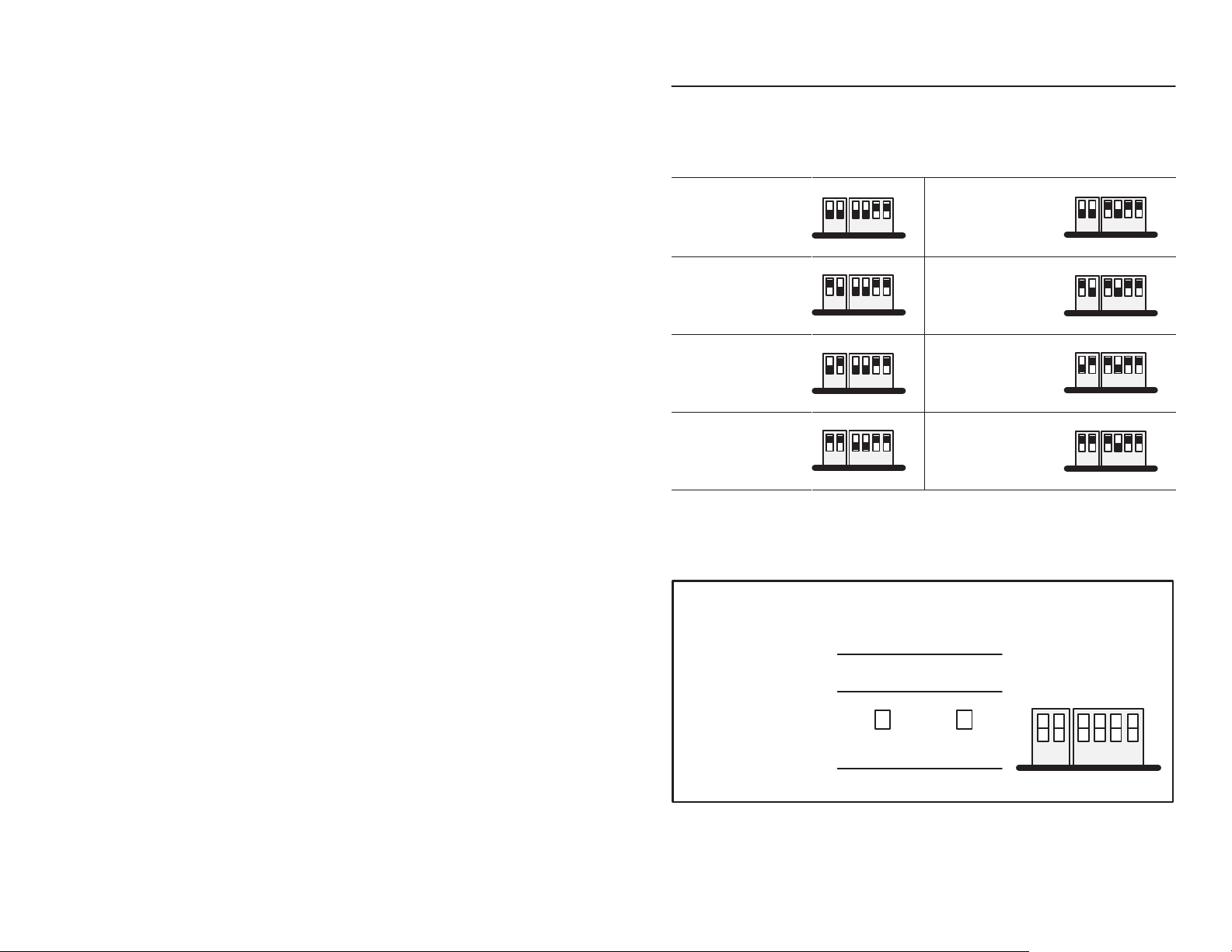
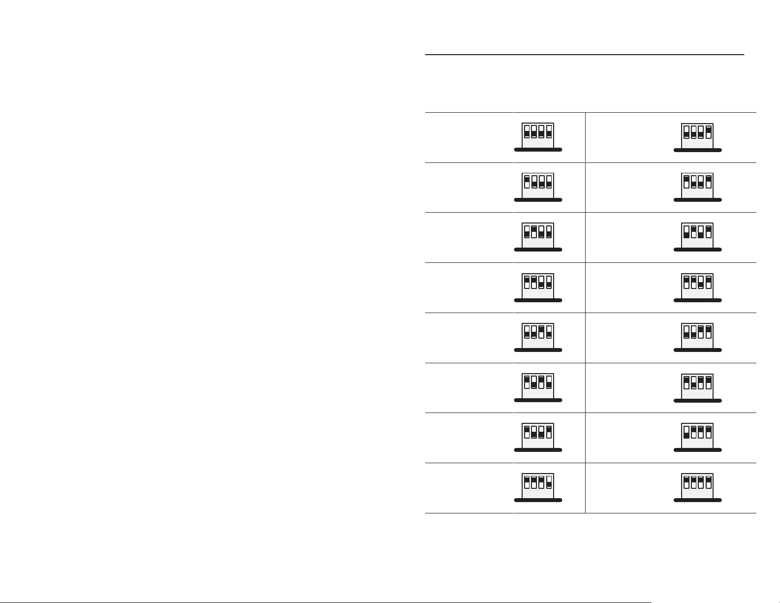
W
orksheet C
Your
base memory address
Switch Settings Base Memory Addr (hex) Switch Settings
up (1)
12 1234
down (0)
up (1)
12 1234
down (0)
up (1)
12 1234
down (0)
up (1)
12 1234
down (0)
D000:0000
factory
recommended setting
D400:0000
D800:0000
DC00:0000
Record the base memory address for the 9220-KTCT:
up (1)
set address &
12 1234
down (0)
up (1)
12 1234
down (0)
up (1)
12 1234
down (0)
up (1)
12 1234
down (0)
Card:
Slot number:
Using default address:
If no, new memory address:
9220-5.1
— November 1996
up (1)
yes no
S2 S1
12 1234
down (0)
Page 7
ControlNet ISA/EISA Bus Tool Installation Instructions 7
Selecting the Base I/O Space Address Location
The host addresses I/O devices on the 9220-KTCT card by using their
I/O space address. The host addresses individual devices through
registers that have addresses based on the I/O space base address.
The registers are 2 bytes long.
The 9220-KTCT is preset to base I/O space address 220. If this address
has been allocated to other interface cards or expansion memory cards
installed in your computer system, you must change the 9220-KTCT’s
switch settings to an open address.
To select a new base I/O space address:
1. Select a new base I/O space address for the card (i.e., to determine the
switch settings for the new address) using the I/O map area of your
host computer’s memory, and Worksheet D, on page 8. Be sure to
choose a block that is 2 bytes long.
Important: The 9220-KTCT card requires 2 bytes of I/O space
for each device.
2. Set the switches to the new base I/O address, using the guide below:
Side ViewFront View
down (0)
up (1)
Front View
MSBLSB
up (1)
1234
down (0)
S3
3. Fill in Worksheet E, on page 9.
4. Follow the instructions that begin on page10.
9220-5.1
— November 1996
Page 8
ControlNet ISA/EISA Bus Tool Installation Instructions8
W
orksheet D
9220-KTCT
Base
I/O Address (hex)
switch settings
200
Switch Settings
up (1)
Base I/O
Address (hex)
300
Switch Settings
up (1)
potential device conflict:
game port
220
factory-set
address &
recommended setting
240
260
280
2A0
2C0
1234
down (0)
up (1)
1234
down (0)
up (1)
1234
down (0)
up (1)
1234
down (0)
up (1)
1234
down (0)
up (1)
1234
down (0)
up (1)
potential device
conflict: prototype cards
320
potential device
conflict: HDD
340
360
380
potential device
conflict: SDLC
3A0
potential device
conflict: SDLC
3C0
1234
down (0)
up (1)
1234
down (0)
up (1)
1234
down (0)
up (1)
1234
down (0)
up (1)
1234
down (0)
up (1)
1234
down (0)
up (1)
potential device
conflict: EGA
2E0
potential device
conflict: GPIB
9220-5.1
— November 1996
1234
down (0)
up (1)
1234
down (0)
potential device
conflict: EGA
3E0
1234
down (0)
up (1)
1234
down (0)
Page 9

ControlNet ISA/EISA Bus Tool Installation Instructions 9
W
orksheet E
Your
base I/O space address
Record the base I/O space address for the 9220-KTCT:
Card:
Slot number:
Using default address:
If no, new I/O space address:
yes no
up (1)
S3
1234
down (0)
9220-5.1
— November 1996
Page 10

ControlNet ISA/EISA Bus Tool Installation Instructions10
Setting the Card’s Switches
ATTENTION: This card uses CMOS technology, which
is highly sensitive to electrostatic discharge (ESD). ESD
!
may be present whenever you are handling this card.
Handling this card without any ESD protection can cause
internal circuit damage that may not be apparent during
installation or initial use. A grounding wrist strap has been
shipped with the 9220-KTCT to be worn during the
installation procedure. Instructions for use of the strap are
found on the back of its package.
Take these precautions to guard
against ESD damage:
• Before handling the card, be sure
to wear the provided static strap and
touch a grounded object to discharge
any built-up static charge.
• Avoid touching the backplane connector or
interface connector pins located on the card.
• If the card is not in use, store it in the static bag
that the card was shipped in.
wrist-strap
grounding
device
Important: Remember, a computer with ac power
disconnected is not a grounded object.
Important: When selecting configuration settings, check for conflicts
with other interface card and system memory. If there is a
conflict, the host computer will not operate properly.
If you have a 386, 486, or Pentium host computer, you must
disable caching and shadow memory for at least the 16K
of memory space occupied by each 9220-KTCT card.
This can usually be accomplished through your CMOS
setup program or memory manager, and must be done
before running applications with the 9220-KTCT card.
9220-5.1
— November 1996
Page 11

ControlNet ISA/EISA Bus Tool Installation Instructions 11
1. Remove the 9220-KTCT from its static-shielded bag.
If you are Then
2.
using the card’s default
memory address setting
setting a new base
memory address
go to step 3.
set the switches to either up or down to reflect the selected
address from Worksheet C, on page 6.
D000:0000
Factory-set
(recommended setting)
address
Front of Switches
S2 S1
12 1234
If you are Then
3.
using the card’s default base
I/O space address setting
setting a new base I/O
space address
220h
Factory-set
(recommended setting)
address
Front of Switches
up (1)
Side ViewFront View
down (0)
down (0)
up (1)
go to page 13.
set the switches to either up or down to reflect the selected
address from Worksheet E, on page 9.
up (1)
Side ViewFront View
S3
1234
down (0)
down (0)
up (1)
9220-5.1
— November 1996
Page 12

ControlNet ISA/EISA Bus Tool Installation Instructions12
E2
9220-KTCT Jumpers
Important: When you receive your card, the jumpers are set in default
positions, as shown below. Do not alter these positions
unless you need to as specified in the table below.
E2
E1
20628-M
E3
For Set jumper
S normal card operation
S field flash upgrade of card’s main code
E2
E1
field flash upgrade of card’s boot code
E1
latching certain address lines that some 286 machines and older may not latch
If you have this computer
286-based or older you may need to install this jumper
then
E3
386-based or newer these address lines are latched in the
computer and the jumper is not required
Important: Allen-Bradley does not support any other E1 and E2
jumper combinations.
9220-5.1
— November 1996
Page 13

ControlNet ISA/EISA Bus Tool Installation Instructions 13
Installing the Card Inside the Computer
Important: Make sure:
• you know how to:
– install hardware in your computer
– configure the computer’s options before you install the card
• the 9220-KTCT will fit in your computer—the card is 4.7” high and
does not fit in all computers
• you consult your computer’s documentation for specific information
To install the card See this section
gather tools for installation
gain access to the computer’
expansion slots
insert the card into the computer Inserting the Card, on page 14.
s
Gather Tools for Installation
You need a Phillips-head or a flat-head screwdriver.
Gather Tools for Installation, below
Accessing the Computer’s Expansion Slots, below
Accessing the Computer’s Expansion Slots
To install the 9220-KTCT, you access your computer’s expansion slots.
Using your computer’s hardware manual for instructions, you:
1. Power down the host computer. Turn off power switch.
2. Remove the computer’s central processing unit (CPU) cover.
3. Select a vacant 16- or 32-bit expansion slot.
Important: The 9220-KTCT will function only in a 16- or 32-bit
ISA/EISA expansion slot.
4. Remove the slot’s expansion cover by loosening the screw on the
back (rear bracket) of the computer.
9220-5.1
— November 1996
Page 14

ControlNet ISA/EISA Bus Tool Installation Instructions14
Inserting the Card
Following the card handling instructions on page 10, you:
1. Make sure you have correctly set all of the switches on the card.
2. Insert the card into the edge connector and tighten the
expansion-slot screw.
3. Turn on the computer to make sure it comes up correctly.
If the computer status is then
powers up
hangs up incorrect you may have to change switch settings
won’t boot from hard drive examine Pentium/SCSI incompatibility
correct go to step 4.
and cycle power.
(if you have a Pentium processor).
4. Replace the CPU cover (when computer comes up correctly).
9220-5.1
— November 1996
Page 15

ControlNet ISA/EISA Bus Tool Installation Instructions 15
Running the Installation Check Utility
Run the installation check utility before you connect the card to the
network to make sure the card has been properly installed.
1. Place the utility disk, that is shipped with the card, in drive A of the
host computer.
If you are running the utility software from
another drive, use the appropriate drive letter.
2. At the DOS prompt, type:
a:\ktctinst Return
Y
ou see a screen similar to this one:
9220-KTCT Card Installation Check Utility
Copyright E1996 Allen-Bradley Company, Inc.
Usage: KTCTINST NetworkAddress [IOaddress]
NetworkAddress= KTCT Network Address, in hex
IOaddress = KTCT I/O base address (Default 220), in hex
In order to run the KTCT installation utility, you must specify the
network address and the I/O address, if other than 220.
For a network address of 3 and I/O address of 260, type:
For a network address of 2 and I/O address of 220 (default), type:
C:\
Version 1.0 — 21-Oct-96
KTCTINST 3 260
KTCTINST 2
3. Type:
a:\ktctinst 2 Return (where 2 is the network address you’ve selected)
Y
ou see:
Warning.. Make sure that the card is not connected to a network. Press any key.
9220-5.1
— November 1996
Page 16

ControlNet ISA/EISA Bus Tool Installation Instructions16
4. Press any key.
You see a similar message:
Succeeded Make sure that the card is not connected to a network.
Succeeded Hard resetting KTCT.
Succeeded I/O Address: 220, Dual Port Address: D000:0000
Boot code version: 1.1 1/24/95, Serial #:
Main code version: 1.1 7/12/95
Succeeded Testing dualport interface
Waiting.. Soft resetting KTCT as network address ID 2. Press any key.
5. Press any key.
You see a similar message:
Succeeded Soft resetting KTCT as network address 2.
Waiting.. Setting KTCT to online. Press any key.
6. Press any key.
You see:
Succeeded Setting KTCT to online. KTCT LEDs should show flashing red.
Waiting.. Setting KTCT to offline. Press any key.
7. Press any key
You see:
Succeeded Setting KTCT to offline. KTCT LEDs should show flashing green.
Waiting.. Resetting KTCT. Press any key.
8. Press any key.
You see:
Succeeded Resetting KTCT. KTCT LEDs should alternate green and red.
Test of KTCT’s basic functionality succeeded. Installation successful.
9220-5.1
— November 1996
Page 17

ControlNet ISA/EISA Bus Tool Installation Instructions 17
Connecting the Card
The 9220-KTCT has these components:
Diagnostic status
indicators
See page 22 for information
about status indicators.
Indicators diagnose only
redundant media
BNC connections.
Redundant media
BNC connectors
A
B
9220-KTCT
Network Access Port (NAP)
RJ-45 connector for connecting
programming terminals to
devices on a ControlNet network
Channel A
BNC connectors for connecting
directly to a ControlNet network
Channel B
ATTENTION: Do not use the 9220-KTCT card to
connect to more than one network at a time. Attempting to
!
connect to a second network will cause erratic operation of
your communication system.
If you are connecting the card See page
to a device already connected to the ControlNet network
directly to a ControlNet network, which requires a tap 20
18
9220-5.1
— November 1996
Page 18

ControlNet ISA/EISA Bus Tool Installation Instructions18
Connecting to a Device on the ControlNet Network
Using the network access cable (cat. no. 1786-CP), you can connect
your card to a ControlNet programmable controller, I/O adapter, or
communication interface.
ATTENTION: Use the 1786-CP cable when
connecting a programming terminal to the network
!
Connecting a portable host computer to a ControlNet link
through a programmable controller or I/O adapter
programming
terminal
through NAPs; using another cable could result in possible
network failures.
9220-KTCT
1786-CP
node
ControlNet link
Connecting a portable host computer to a
ControlNet link through a desktop host computer
portable
host
computer
1784-KTC
1786-CP
ControlNet link
9220-KTCT
desktop
host
computer
Important: The 1786-CP cable can be plugged into any ControlNet
product’s NAP to provide programming capability on the
ControlNet network. A programming terminal connected
through this cable is counted as a node and must have a
unique address.
9220-5.1
— November 1996
Page 19

ControlNet ISA/EISA Bus Tool Installation Instructions 19
Co
1
Co
1. Connect one end of the 1786-CP to the NAP on the 9220-KTCT card.
9220-KTCT
AB
9220-KTCT installed in 16-bit ISA- or
32-bit EISA-compatible computer
2. Connect the other end of the 1786-CP to the NAP on any other
ControlNet device connected via taps to the network.
This table shows the wiring for the 1786-CP cable.
Wire Number Signal Mnemonic Signal Name
1 ISO-GND Isolated Ground
2 N.C. No Connection
3 PTTX-H Transmit Data High
nnector
nnector 2
4 PTTX-L Transmit Data Low
5 PTRX-L Receive Data Low
6 PTRX-H Receive Data High
7 N.C. No Connection
8 ISO-GND Isolated Ground
1 ISO-GND Isolated Ground
2 N.C. No Connection
3 PTRX-H Receive Data High
4 PTRX-L Receive Data Low
5 PTTX-L Transmit Data Low
6 PTTX-H Transmit Data High
7 N.C. No Connection
8 ISO-GND Isolated Ground
9220-5.1
— November 1996
Page 20

ControlNet ISA/EISA Bus Tool Installation Instructions20
Connecting Directly to the ControlNet Link
To connect the card directly to a ControlNet link, you connect
the card to taps as shown below.
desktop
host
computer
9220-KTCT
1786-TPR, -TPS,
-TPYR, or -TPYS
tap
ControlNet link
1. Remove and save the taps’ dust caps (located on the straight or
right-angle connectors).
dust cap
tap on
trunk cable A
dust cap
tap on
trunk cable B
9220-5.1
— November 1996
Page 21

ControlNet ISA/EISA Bus Tool Installation Instructions 21
2.
ATTENTION: If you connect the 9220-KTCT to a
cable system that does not support redundant media,
!
connect the tap drop cable to the BNC connector labeled
channel A. Channel B is left open.
If the cable system is redundant, connect the product
such that all devices on the network use the same cable
for the same channel. That is, all channel A connectors
connect to one cable; all channel B connectors connect
to the other.
Connect the tap’s straight or right-angle connector To this channel on the card
from trunk cable A
from trunk cable B channel B
tap on
trunk cable A
to
9220-KTC
T,
channel A
to
9220-KTC
T
,
channel B
channel A
tap on
trunk cable B
9220-5.1
— November 1996
Page 22

ControlNet ISA/EISA Bus Tool Installation Instructions22
ree o
Interpreting the Status Indicators
The status indicators on the 9220-KTCT give you information about the
card and the network when you’re connected via the BNC connectors.
The table below outlines the states, and explains what each state means
to you and the action you should take, if any, to correct that state.
• steady – indicator
• alternating – the
both indicators
• flashing – the
independent
A B
and
off
steady red
alternating red/green
alternating red/of
A B
or
off
steady green
flashing green/of
flashing red/of
flashing red/green
À The
configuration node is the node responsible for distributing ControlNet configuration data to all nodes on
the network.
is on continuously in the defined state.
two indicators alternate between the two defined states at the same time (applies to
viewed together
indicator alternates between the two defined states (applies to each indicator
of the other). If both indicators are flashing, they must flash together
f
f
f
). The two indicators are always in opposite states, out of phase.
Cause Action
no power none or power up
faulted unit
self-test none
incorrect node configuration
Cause Action
channel disabled
normal operation
temporary errors
node is not configured to go on line
media fault
no other nodes present on network add other nodes to the network
incorrect network configuration
cycle power or reset unit
If fault persists, contact A-B representative
or distributor
check network address and other
ControlNet configuration parameters
program network for redundant media,
if required
none
none; unit will self-correct
make sure the configuration node is
present and working
check media for broken cables, loose
connectors, missing terminators, etc.
cycle power or reset unit
If fault persists, contact A-B representative
or distributor
.
.
viewed
, in phase.
À
9220-5.1
— November 1996
Page 23

ControlNet ISA/EISA Bus Tool Installation Instructions 23
Environmental Specifications
The operating parameters describe the environment within the
9220-KTCT slot. Refer to the documentation for your computer for
environmental requirements. The 9220-KTCT card should not exceed
those specifications.
Operating Nonoperating
Slot Temperature
Humidity 5 to 95% without condensation 5 to 95% without condensation
Vibration 10 to 150 Hz, constant .012 in
Shock 30G peak/11 ms 50G peak/11 ms
!
0 to 50° C (32 to 122° F) –40 to 85° C ( –40 to 185° F)
not applicable
displacement
10 to 150 Hz, constant 2.0G
acceleration
ATTENTION: This digital apparatus does not exceed the
Class A limits for radio noise emissions from digital
apparatus set out in the Radio Interference Regulations of
the Canadian Department of Communications.
Le présent appareil numérique n’émet pas de bruits
radioélectriques dépassant les limites applicables aux
appareils numériques de la class A prescrites dans le
Règlement sur le brouillage radioélectrique édicté par le
ministère des Communications du Canada.
ControlNet and INTERCHANGE are trademarks of Allen-Bradley Company, Inc.
9220-5.1
— November 1996
Page 24

ControlNet ISA/EISA Bus Tool Installation Instructions24
Worldwide representation.
Argentina •
Colombia • Costa Rica • Croatia • Cyprus • Czech Republic • Denmark • Ecuador • Egypt • El Salvador
Finland •
Indonesia •
Mexico •
Puerto Rico • Qatar • Romania • Russia–CIS • Saudi Arabia • Singapore
South Africa, Republic • Spain • Sweden
United Arab Emirates • United Kingdom • United States • Uruguay • V
Allen-Bradley Headquarters, 1201 South Second Street, Milwaukee, WI 53204 USA,
Tel: (1) 414 382-2000 Fax: (1) 414 382-4444
Publication
Supersedes
9220-5.1
Australia • Austria • Bahrain • Belgium
• Brazil •
Bulgaria • Canada • Chile • China, PRC
France • Germany • Greece • Guatemala • Honduras • Hong Kong • Hungary • Iceland • India
Ireland • Israel • Italy • Jamaica •
Netherlands
• New
Zealand • Norway
9220-5.1 — November 1996
Publication 9220–5.1 – March 1996
— November 1996
Japan • Jordan • Korea • Kuwait • Lebanon
• Pakistan •
Peru
• Philippines •
• Slovakia • Slovenia •
• Switzerland • T
aiwan
• Thailand • T
enezuela • Y
Copyright
1996 Allen-Bradley Company, Inc. Printed in USA
Poland • Portugal
• Malaysia •
urkey •
ugoslavia
PN
955127–93
•
•
•
•
 Loading...