

Page 1
Temperature Controllers
USER MANUAL
Bulletin 900-TC8, 900-TC16, & 900-TC32
Series B
Page 2

2
Page 3
3
ATTENTION
!
Important User Information
Because of the variety of uses for the prod ucts described in this publi cation,
those responsible for the application and use of this control equipment must
satisfy themselves that all necessary steps have been taken to assure that
each application and use meets all performance and safety requirements,
including any applicable laws, regulations, codes and standards.
The illustrations, charts, sample programs and layout examples shown in
this guide are intended solely for purposes of example. Since there are many
variables and requirements associated with any particular installation,
Rockwell Automation does not assume responsibility or liability (to include
intellectual property liability) for actual use based upon the examples sho wn
in this publication.
Rockwell Automation publication SGI-1.1, Safety Guidelines for the
Application, Installation and Maintenance of Solid-State Control (available
from your local Allen-Bradley sales office), describes some important
differences between solid-state equipment and electromechanical devices
that should be taken into consideration when applying products such as
those described in this publication.
Reproduction of the contents of this copyrighted publication, in whole or
part, without written permission of Rockwell Automation, is prohibited.
Safety Precautions
Safety Signal Words
This manual uses the following signal word to mark safety precautions for the
Bulletin 900-TC8, 900-TC16, and 900-TC32 Temperature/Process
Controllers.
These precautions provide important information for the safe application of
the Temperature/Process Controller. You must make sure to follow the
instructions provided in all safety precautions.:
Identifies information about practices or circumstance s
that can lead to personal injury or death, property damage
or economic loss
Page 4

4
IMPORTANT
Attention statements help you to:
• identify a hazard
• avoid a hazard
• recognize the consequences
Identifies information that is critical for successful
application and understanding of the product.
Trademark List
900Builder and 900BuilderLite are registered trademarks of Rockwell Automation, Inc.
European Communities (EC) Directive Compliance
If this product has the CE mark it is approved for installation within the
European Union and EEA regions. It has been designed and tested to meet
the following directives.
EMC Directive
This product is tested to meet the Council Directive 89/336/EC
Electromagnetic Compatibility (EMC) by applying the following standards,
in whole or in part, documented in a technical construction file:
EN 61326 EMC Requirements — Electrical Equipment for Control,
Measurement and Laboratory Use
This product is intended for use in an industrial environment.
Low Voltage Directive
This product is tested to meet Council Directive 73/23/EEC Low Voltage,
by applying the safety requirements of EN 61010-1 Safety Requirements
for Electrical Equipment for Control, Measurement and Laboratory Use —
General Requirements. For specific information, see the appropriate
sections in this publication, as well as the Allen-Bradley publication
Industrial Automation Wiring and Grounding Guidelines For Noise
Immunity, Publication 1770-4.1.
This equipment is classified as open equipment and must be mounted in an
enclosure during operation to provide safety protection.
Page 5

Table of Contents
Table of Contents
Important User Information . . . . . . . . . . . . . . . . . . . . . . . . . . . . . . . . 1-3
Safety Precautions . . . . . . . . . . . . . . . . . . . . . . . . . . . . . . . . . . . . . . . . 1-3
Safety Signal Words . . . . . . . . . . . . . . . . . . . . . . . . . . . . . . . . . . . . 1-3
European Communities (EC) Directive Compliance . . . . . . . . . 1-4
Low Voltage Directive. . . . . . . . . . . . . . . . . . . . . . . . . . . . . . . . . . 1-4
Preface
Bulletin 900 Input & Output
Overview
Conventions Used in This Manual . . . . . . . . . . . . . . . . . . . . . . . . . . . P-i
Meanings of Abbreviations . . . . . . . . . . . . . . . . . . . . . . . . . . . . . . P-i
Series B Controllers . . . . . . . . . . . . . . . . . . . . . . . . . . . . . . . . . . . . . . . P-ii
Series B Upgrades . . . . . . . . . . . . . . . . . . . . . . . . . . . . . . . . . . . . . P-ii
900-TC8x . . . . . . . . . . . . . . . . . . . . . . . . . . . . . . . . . . . . . . . . . . . . P-ii
900-TC16x . . . . . . . . . . . . . . . . . . . . . . . . . . . . . . . . . . . . . . . . . . . P-ii
900-TC32x . . . . . . . . . . . . . . . . . . . . . . . . . . . . . . . . . . . . . . . . . . . P-ii
Terminal Arrangements . . . . . . . . . . . . . . . . . . . . . . . . . . . . . . . . . . . P-iv
Body Removal . . . . . . . . . . . . . . . . . . . . . . . . . . . . . . . . . . . . . . . . . . . P-v
900-TC8, 900-TC16, & 900-TC32 Ratings . . . . . . . . . . . . . . . . . . . . P-vi
Characteristics. . . . . . . . . . . . . . . . . . . . . . . . . . . . . . . . . . . . . . . . . . . P-vi
Communications Characteristics . . . . . . . . . . . . . . . . . . . . . . . . . . . . P-vii
Other Upgrades . . . . . . . . . . . . . . . . . . . . . . . . . . . . . . . . . . . . . . . . P-viii
Option Units . . . . . . . . . . . . . . . . . . . . . . . . . . . . . . . . . . . . . . . . P-ix
How to Read Display Symbols . . . . . . . . . . . . . . . . . . . . . . . . . . . . . . P-x
Chapter 1
I/O Configurations & Main Functions. . . . . . . . . . . . . . . . . . . . . . . . 1-1
Features . . . . . . . . . . . . . . . . . . . . . . . . . . . . . . . . . . . . . . . . . . . . . 1-4
Main Functions . . . . . . . . . . . . . . . . . . . . . . . . . . . . . . . . . . . . . . . 1-4
Controller Hardware Versions. . . . . . . . . . . . . . . . . . . . . . . . . . . . . . . 1-7
900-TC8 . . . . . . . . . . . . . . . . . . . . . . . . . . . . . . . . . . . . . . . . . . . . . 1-8
900-TC16 . . . . . . . . . . . . . . . . . . . . . . . . . . . . . . . . . . . . . . . . . . . . 1-9
900-TC32 . . . . . . . . . . . . . . . . . . . . . . . . . . . . . . . . . . . . . . . . . . . 1-10
Front Panels & General Functions . . . . . . . . . . . . . . . . . . . . . . . . . . 1-11
Display Meanings. . . . . . . . . . . . . . . . . . . . . . . . . . . . . . . . . . . . . 1-12
Operation Indicators 1,2,3... . . . . . . . . . . . . . . . . . . . . . . . . . . . . 1-13
Basic Keypad Functions . . . . . . . . . . . . . . . . . . . . . . . . . . . . . . . 1-14
Chapter 2
Preparations
1-1 Publication 900-UM007D-EN-E - January 2011
Hardware Installation. . . . . . . . . . . . . . . . . . . . . . . . . . . . . . . . . . . . . . 2-1
Approximate Dimensions . . . . . . . . . . . . . . . . . . . . . . . . . . . . . . . 2-1
Panel Cutout Dimensions . . . . . . . . . . . . . . . . . . . . . . . . . . . . . . . 2-2
System Wiring and Installation Guidelines. . . . . . . . . . . . . . . . . . 2-4
Panel Mounting — 900-TC8. . . . . . . . . . . . . . . . . . . . . . . . . . . . . 2-7
Setting Up the 900-TC8 Controller with the Optional Units . . . 2-9
Page 6

1-2 Table of Contents
Panel Mounting . . . . . . . . . . . . . . . . . . . . . . . . . . . . . . . . . . . . . . 2-13
Bulletin 900 Wiring Terminals. . . . . . . . . . . . . . . . . . . . . . . . . . . . . . 2-15
Wiring Guidelines and Precautions. . . . . . . . . . . . . . . . . . . . . . . 2-17
Wiring . . . . . . . . . . . . . . . . . . . . . . . . . . . . . . . . . . . . . . . . . . . . . . 2-18
Using the Direct PC Communications Port . . . . . . . . . . . . . . . . . . . 2-30
Procedure . . . . . . . . . . . . . . . . . . . . . . . . . . . . . . . . . . . . . . . . . . . 2-30
Chapter 3
Configuration & Basic Operation
How Function Groups Are Configured and Operating the Keys on the
Front Panel . . . . . . . . . . . . . . . . . . . . . . . . . . . . . . . . . . . . . . . . . . . . . . 3-3
Selecting Parameters . . . . . . . . . . . . . . . . . . . . . . . . . . . . . . . . . . . 3-7
Changing Parameters/Loading Values into Controller Memory. 3-7
Communications Function . . . . . . . . . . . . . . . . . . . . . . . . . . . . . . . . . 3-8
Setting Up Communications Parameter Data . . . . . . . . . . . . . . . 3-9
Initial Setup Examples . . . . . . . . . . . . . . . . . . . . . . . . . . . . . . . . . . . . . 3-9
Configuring the Input Type. . . . . . . . . . . . . . . . . . . . . . . . . . . . . . . . 3-12
Input Type . . . . . . . . . . . . . . . . . . . . . . . . . . . . . . . . . . . . . . . . . . 3-12
Selecting °C/°F . . . . . . . . . . . . . . . . . . . . . . . . . . . . . . . . . . . . . . . . . 3-14
Temperature Units. . . . . . . . . . . . . . . . . . . . . . . . . . . . . . . . . . . . 3-14
Configuring the SP . . . . . . . . . . . . . . . . . . . . . . . . . . . . . . . . . . . . . . . 3-15
Changing the SP. . . . . . . . . . . . . . . . . . . . . . . . . . . . . . . . . . . . . . 3-15
Selecting PID Control or ON/OFF Control . . . . . . . . . . . . . . . . . . 3-16
Overview . . . . . . . . . . . . . . . . . . . . . . . . . . . . . . . . . . . . . . . . . . . 3-16
2-PID Control . . . . . . . . . . . . . . . . . . . . . . . . . . . . . . . . . . . . . . . 3-16
ON/OFF Control . . . . . . . . . . . . . . . . . . . . . . . . . . . . . . . . . . . . 3-16
Configuring the Output Parameters . . . . . . . . . . . . . . . . . . . . . . . . . 3-17
Control Period . . . . . . . . . . . . . . . . . . . . . . . . . . . . . . . . . . . . . . . 3-17
Direct/Reverse Operation. . . . . . . . . . . . . . . . . . . . . . . . . . . . . . 3-17
Assigned Output Functions . . . . . . . . . . . . . . . . . . . . . . . . . . . . 3-20
Auxiliary Output Opening or Closing in Alarm . . . . . . . . . . . . . . . . 3-25
Executing the ON/OFF Control Method . . . . . . . . . . . . . . . . . . . . 3-25
Overview . . . . . . . . . . . . . . . . . . . . . . . . . . . . . . . . . . . . . . . . . . . 3-25
ON/OFF Control Parameters . . . . . . . . . . . . . . . . . . . . . . . . . . 3-25
ON/OFF Control Setup . . . . . . . . . . . . . . . . . . . . . . . . . . . . . . . 3-27
Determining PID Constants (AT, ST, Manual Setup) . . . . . . . . . . . 3-30
AT (Auto-Tuning) . . . . . . . . . . . . . . . . . . . . . . . . . . . . . . . . . . . . 3-30
ST (Self-Tuning). . . . . . . . . . . . . . . . . . . . . . . . . . . . . . . . . . . . . . 3-33
Conditions that Start Self-Tuning (SRT) . . . . . . . . . . . . . . . . . . 3-34
Self-Tuning (ST) Stable Range . . . . . . . . . . . . . . . . . . . . . . . . . . 3-35
RT (Robust Tuning). . . . . . . . . . . . . . . . . . . . . . . . . . . . . . . . . . . 3-36
Manual PID Setup . . . . . . . . . . . . . . . . . . . . . . . . . . . . . . . . . . . . 3-39
Alarm Outputs . . . . . . . . . . . . . . . . . . . . . . . . . . . . . . . . . . . . . . . . . . 3-42
Alarm Types . . . . . . . . . . . . . . . . . . . . . . . . . . . . . . . . . . . . . . . . . 3-42
Alarm Value . . . . . . . . . . . . . . . . . . . . . . . . . . . . . . . . . . . . . . . . . 3-44
Publication 900-UM007D-EN-E - January 2011
Page 7

Table of Contents 1-3
PV Change Rate Alarm . . . . . . . . . . . . . . . . . . . . . . . . . . . . . . . . . . . 3-45
Precaution. . . . . . . . . . . . . . . . . . . . . . . . . . . . . . . . . . . . . . . . . . . 3-46
Heater Burnout Alarm (HBA), Heater Short Alarm (HSA), and Heater
Overcurrent Alarm (HOA) . . . . . . . . . . . . . . . . . . . . . . . . . . . . . . . . 3-46
HBA, HSA, and HOA Alarm Detection . . . . . . . . . . . . . . . . . . 3-46
Installing Current Transformers (CT). . . . . . . . . . . . . . . . . . . . . 3-48
How to Calculate Heater Current Detection Values . . . . . . . . . 3-50
Application Examples . . . . . . . . . . . . . . . . . . . . . . . . . . . . . . . . . 3-51
Heater Burnout Alarm (HBA) Setup . . . . . . . . . . . . . . . . . . . . . 3-55
HS Alarm Setup . . . . . . . . . . . . . . . . . . . . . . . . . . . . . . . . . . . . . . 3-58
Heater Overcurrent Alarm Set-up. . . . . . . . . . . . . . . . . . . . . . . . . . . 3-60
Moving to the Advanced Setting Function Group . . . . . . . . . . 3-60
Configure Overcurrent Detection. . . . . . . . . . . . . . . . . . . . . . . . 3-61
Set-up of the No. 3 Display . . . . . . . . . . . . . . . . . . . . . . . . . . . . . . . . 3-62
MV Display for Heating and Cooling Control . . . . . . . . . . . . . . . . . 3-63
System Setup/Operational Considerations. . . . . . . . . . . . . . . . . . . . 3-65
Chapter 4
Parameter Adjustments &
Application Considerations
Shifting Input Values . . . . . . . . . . . . . . . . . . . . . . . . . . . . . . . . . . . . . . 4-1
1-Point (Uniform) Shift . . . . . . . . . . . . . . . . . . . . . . . . . . . . . . . . . 4-1
2-Point Shift . . . . . . . . . . . . . . . . . . . . . . . . . . . . . . . . . . . . . . . . . . 4-3
How to Calculate Input Shift Values . . . . . . . . . . . . . . . . . . . . . . 4-3
Using the 1-Point Shift Method . . . . . . . . . . . . . . . . . . . . . . . . . . 4-4
Using the 2-Point Shift Method . . . . . . . . . . . . . . . . . . . . . . . . . . 4-5
Alarm Functions/Parameters . . . . . . . . . . . . . . . . . . . . . . . . . . . . . . . 4-8
Alarm Hysteresis . . . . . . . . . . . . . . . . . . . . . . . . . . . . . . . . . . . . . . 4-8
Standby Alarm Sequence . . . . . . . . . . . . . . . . . . . . . . . . . . . . . . . . 4-8
Alarm Latch . . . . . . . . . . . . . . . . . . . . . . . . . . . . . . . . . . . . . . . . . . 4-9
Summary of Alarm Operations . . . . . . . . . . . . . . . . . . . . . . . . . . . . . . 4-9
Configuration of Scaling Upper-Limits and Scaling Lower-Limits for
Analog Input. . . . . . . . . . . . . . . . . . . . . . . . . . . . . . . . . . . . . . . . . . . . 4-10
Overview . . . . . . . . . . . . . . . . . . . . . . . . . . . . . . . . . . . . . . . . . . . 4-10
Executing the Heating and Cooling Control Mode . . . . . . . . . . . . . 4-12
Overview . . . . . . . . . . . . . . . . . . . . . . . . . . . . . . . . . . . . . . . . . . . 4-12
Dead Band (Heating and Cooling Control) . . . . . . . . . . . . . . . . 4-13
Setup of Heating and Cooling. . . . . . . . . . . . . . . . . . . . . . . . . . . 4-15
Using the Event Input Feature — 900-TC8 & 900-TC16. . . . . . . . 4-16
Multi-SP . . . . . . . . . . . . . . . . . . . . . . . . . . . . . . . . . . . . . . . . . . . . 4-19
Selecting Multi-SP by Keypad Operation . . . . . . . . . . . . . . . . . . 4-19
Multi-SP Setup . . . . . . . . . . . . . . . . . . . . . . . . . . . . . . . . . . . . . . . 4-20
Executing RUN/STOP Controller Mode Change. . . . . . . . . . . 4-23
Switching Between Auto and Manual Control . . . . . . . . . . . . . . 4-23
Controlling the Start of the Simple Program Function . . . . . . . 4-23
Control by Inverting Direct/Reverse Operation . . . . . . . . . . . . 4-24
Publication 900-UM007D-EN-E - January 2011
Page 8

1-4 Table of Contents
Switching 100% AT Execute/Cancel . . . . . . . . . . . . . . . . . . . . . 4-24
Switching 40% ATExecute/Cancel . . . . . . . . . . . . . . . . . . . . . . 4-25
Switching Setting Change Enable/Disable. . . . . . . . . . . . . . . . . 4-25
Switching Alarm Latch Cancel . . . . . . . . . . . . . . . . . . . . . . . . . . 4-25
Parameters . . . . . . . . . . . . . . . . . . . . . . . . . . . . . . . . . . . . . . . . . . 4-26
Configuring the SP Upper- and Lower-Limit Values. . . . . . . . . . . . 4-26
Set Point Limiter . . . . . . . . . . . . . . . . . . . . . . . . . . . . . . . . . . . . . 4-26
Application Considerations . . . . . . . . . . . . . . . . . . . . . . . . . . . . . 4-27
Set Point Limit Setup. . . . . . . . . . . . . . . . . . . . . . . . . . . . . . . . . . 4-27
Executing the SP Ramp Function to Limit the SP Rate of Change 4-29
SP Ramp. . . . . . . . . . . . . . . . . . . . . . . . . . . . . . . . . . . . . . . . . . . . 4-29
SP Ramp Application Considerations. . . . . . . . . . . . . . . . . . . . . 4-30
To Move to the Advanced Setting Function Group . . . . . . . . . . . . 4-31
Using the Key Protect Function Group . . . . . . . . . . . . . . . . . . . . . . 4-33
Key Protect . . . . . . . . . . . . . . . . . . . . . . . . . . . . . . . . . . . . . . . . . 4-33
PV Color Change . . . . . . . . . . . . . . . . . . . . . . . . . . . . . . . . . . . . . . . . 4-39
PV Color Change Function. . . . . . . . . . . . . . . . . . . . . . . . . . . . . 4-39
Setting. . . . . . . . . . . . . . . . . . . . . . . . . . . . . . . . . . . . . . . . . . . . . . 4-42
Alarm Delays . . . . . . . . . . . . . . . . . . . . . . . . . . . . . . . . . . . . . . . . . . . 4-44
Alarm Delays . . . . . . . . . . . . . . . . . . . . . . . . . . . . . . . . . . . . . . . . 4-44
Loop Break Alarm . . . . . . . . . . . . . . . . . . . . . . . . . . . . . . . . . . . . . . . 4-47
Loop Break Alarm (LBA) . . . . . . . . . . . . . . . . . . . . . . . . . . . . . . 4-47
Performing Manual Control . . . . . . . . . . . . . . . . . . . . . . . . . . . . . . . 4-53
Manual Operation . . . . . . . . . . . . . . . . . . . . . . . . . . . . . . . . . . . . 4-53
Manual MV Limit Enable . . . . . . . . . . . . . . . . . . . . . . . . . . . . . . 4-54
Using the Transfer Output . . . . . . . . . . . . . . . . . . . . . . . . . . . . . . . . 4-62
Transfer Output Function. . . . . . . . . . . . . . . . . . . . . . . . . . . . . . 4-62
Using the Simple Program Function . . . . . . . . . . . . . . . . . . . . . . . . . 4-66
Simple Program Function . . . . . . . . . . . . . . . . . . . . . . . . . . . . . . 4-66
Operation at the Program End . . . . . . . . . . . . . . . . . . . . . . . . . . 4-69
Output Adjustment Functions . . . . . . . . . . . . . . . . . . . . . . . . . . . . . 4-75
Output Limits. . . . . . . . . . . . . . . . . . . . . . . . . . . . . . . . . . . . . . . . 4-75
MV at Stop . . . . . . . . . . . . . . . . . . . . . . . . . . . . . . . . . . . . . . . . . . 4-75
MV at PV Error . . . . . . . . . . . . . . . . . . . . . . . . . . . . . . . . . . . . . . 4-76
Using the Extraction of Square Root Parameter . . . . . . . . . . . . 4-77
Setting the Rate of MV Variation . . . . . . . . . . . . . . . . . . . . . . . . 4-80
Setting the PF Key . . . . . . . . . . . . . . . . . . . . . . . . . . . . . . . . . . . . 4-82
Monitor/Setting Item. . . . . . . . . . . . . . . . . . . . . . . . . . . . . . . . . . . . . 4-83
Monitor/Setting Item . . . . . . . . . . . . . . . . . . . . . . . . . . . . . . . . . 4-83
Counting Control Output ON/OFF Operations . . . . . . . . . . . . . . 4-87
Control Output ON/OFF Count Function. . . . . . . . . . . . . . . . 4-87
Displaying PV/SV Status . . . . . . . . . . . . . . . . . . . . . . . . . . . . . . 4-90
Publication 900-UM007D-EN-E - January 2011
Page 9

Chapter 5
Table of Contents 1-5
Parameter Functions & Definitions
Conventions Used in This Chapter . . . . . . . . . . . . . . . . . . . . . . . . . . . 5-1
About the Parameter Display . . . . . . . . . . . . . . . . . . . . . . . . . . . . 5-1
Alarms . . . . . . . . . . . . . . . . . . . . . . . . . . . . . . . . . . . . . . . . . . . . . . 5-1
Protect Function Group . . . . . . . . . . . . . . . . . . . . . . . . . . . . . . . . . . . 5-1
Move to Protect Function Group. . . . . . . . . . . . . . . . . . . . . . . . . 5-3
Operation/Adjustment Protection . . . . . . . . . . . . . . . . . . . . . . . . 5-3
Initial Setting/Communications Protection . . . . . . . . . . . . . . . . . 5-4
Setting/Configuration Change Protection . . . . . . . . . . . . . . . . . . 5-4
PF Key Protect. . . . . . . . . . . . . . . . . . . . . . . . . . . . . . . . . . . . . . . . 5-5
Parameter Mask Enable. . . . . . . . . . . . . . . . . . . . . . . . . . . . . . . . . 5-5
Password to Move to Protect Function Group . . . . . . . . . . . . . . 5-5
Operation Function Group . . . . . . . . . . . . . . . . . . . . . . . . . . . . . . . . . 5-6
PV (Process Value) . . . . . . . . . . . . . . . . . . . . . . . . . . . . . . . . . . . . 5-7
PV/SP – Process Value/Set Point – No. 1 Display
PV/SP – Process Value/Set Point – No. 2 Display (900-TC8) . 5-8
No. 3 Display (900-TC8) . . . . . . . . . . . . . . . . . . . . . . . . . . . . . . . . 5-8
Auto Manual Switch . . . . . . . . . . . . . . . . . . . . . . . . . . . . . . . . . . 5-10
Multi-SP (Set Point 0…3) . . . . . . . . . . . . . . . . . . . . . . . . . . . . . . 5-10
Set Point During SP Ramp . . . . . . . . . . . . . . . . . . . . . . . . . . . . . 5-10
Heater Current 1 Value Monitor. . . . . . . . . . . . . . . . . . . . . . . . . 5-11
Heater Current 2 Value Monitor. . . . . . . . . . . . . . . . . . . . . . . . . 5-12
Leakage Current 1 Monitor . . . . . . . . . . . . . . . . . . . . . . . . . . . . . 5-13
Leakage Current 2 Monitor . . . . . . . . . . . . . . . . . . . . . . . . . . . . . 5-14
Program Start . . . . . . . . . . . . . . . . . . . . . . . . . . . . . . . . . . . . . . . . 5-15
Soak Time Remain. . . . . . . . . . . . . . . . . . . . . . . . . . . . . . . . . . . . 5-15
RUN/STOP. . . . . . . . . . . . . . . . . . . . . . . . . . . . . . . . . . . . . . . . . 5-16
Alarm Value 1 . . . . . . . . . . . . . . . . . . . . . . . . . . . . . . . . . . . . . . . 5-16
Alarm Value 2 (900-TC8, 900-TC16) . . . . . . . . . . . . . . . . . . . . . 5-17
Alarm Value 3 (900-TC8) . . . . . . . . . . . . . . . . . . . . . . . . . . . . . . 5-18
Upper-Limit Alarm Value 1 . . . . . . . . . . . . . . . . . . . . . . . . . . . . 5-18
Lower-Limit Alarm Value 1 . . . . . . . . . . . . . . . . . . . . . . . . . . . . 5-18
Upper-Limit Alarm Value 2 . . . . . . . . . . . . . . . . . . . . . . . . . . . . 5-19
Lower-Limit Alarm Value 2 (900-TC8, 900-TC16) . . . . . . . . . . 5-19
Upper-Limit Alarm Value 3 . . . . . . . . . . . . . . . . . . . . . . . . . . . . 5-20
Lower-Limit Alarm Value 3 (900-TC8 only) . . . . . . . . . . . . . . . 5-20
MV Monitor (Heating) . . . . . . . . . . . . . . . . . . . . . . . . . . . . . . . . 5-21
MV Monitor (Cooling) . . . . . . . . . . . . . . . . . . . . . . . . . . . . . . . . 5-22
Adjustment Function Group . . . . . . . . . . . . . . . . . . . . . . . . . . . . . . . 5-22
Adjustment Function Group Display . . . . . . . . . . . . . . . . . . . . . 5-24
AT Execute/Cancel . . . . . . . . . . . . . . . . . . . . . . . . . . . . . . . . . . . 5-25
Communications Writing . . . . . . . . . . . . . . . . . . . . . . . . . . . . . . 5-26
Heater Current 1 Value Monitor. . . . . . . . . . . . . . . . . . . . . . . . . 5-26
Heater Current 1 Value Monitor. . . . . . . . . . . . . . . . . . . . . . . . . 5-27
Leakage Current 1 Monitor (900-TC8, 900-TC16) . . . . . . . . . . 5-28
Publication 900-UM007D-EN-E - January 2011
Page 10

1-6 Table of Contents
Leakage Current 2 Monitor (900-TC8, 900-TC16) . . . . . . . . . . 5-29
Heater Burnout Detection 1 (900-TC8, 900-TC16). . . . . . . . . . 5-30
Heater Burnout Detection 2 (900-TC8, 900-TC16). . . . . . . . . . 5-31
HS Alarm 1 (900-TC8, 900-TC16) . . . . . . . . . . . . . . . . . . . . . . . 5-31
HS Alarm 2 (900-TC8, 900-TC16) . . . . . . . . . . . . . . . . . . . . . . . 5-32
Set Point 0 . . . . . . . . . . . . . . . . . . . . . . . . . . . . . . . . . . . . . . . . . . 5-33
Set Point 1 . . . . . . . . . . . . . . . . . . . . . . . . . . . . . . . . . . . . . . . . . . 5-33
Set Point 2 . . . . . . . . . . . . . . . . . . . . . . . . . . . . . . . . . . . . . . . . . . 5-33
Set Point 3 . . . . . . . . . . . . . . . . . . . . . . . . . . . . . . . . . . . . . . . . . . 5-33
Temperature Input Shift . . . . . . . . . . . . . . . . . . . . . . . . . . . . . . . 5-34
Upper-Limit Temperature Input Shift Value,
Lower-Limit Temperature Input Shift Value . . . . . . . . . . . . . . . 5-35
Proportional Band, Integral Time, Derivative Time . . . . . . . . . 5-35
Cooling Coefficient . . . . . . . . . . . . . . . . . . . . . . . . . . . . . . . . . . . 5-36
Dead Band . . . . . . . . . . . . . . . . . . . . . . . . . . . . . . . . . . . . . . . . . . 5-37
Manual Reset Value . . . . . . . . . . . . . . . . . . . . . . . . . . . . . . . . . . . 5-38
Hysteresis (Heating)
Hysteresis (Cooling). . . . . . . . . . . . . . . . . . . . . . . . . . . . . . . . . . . 5-38
Soak Time. . . . . . . . . . . . . . . . . . . . . . . . . . . . . . . . . . . . . . . . . . . 5-39
Wait Band. . . . . . . . . . . . . . . . . . . . . . . . . . . . . . . . . . . . . . . . . . . 5-40
MV at Stop . . . . . . . . . . . . . . . . . . . . . . . . . . . . . . . . . . . . . . . . . . 5-40
MV at PV Error . . . . . . . . . . . . . . . . . . . . . . . . . . . . . . . . . . . . . . 5-41
SP Ramp Set Value . . . . . . . . . . . . . . . . . . . . . . . . . . . . . . . . . . . 5-41
MV (Manipulated Variable) Upper-Limit,
MV (Manipulated Variable) Lower-Limit . . . . . . . . . . . . . . . . . . 5-42
MV Upper-Limit . . . . . . . . . . . . . . . . . . . . . . . . . . . . . . . . . . . . . 5-42
MV Lower-Limit . . . . . . . . . . . . . . . . . . . . . . . . . . . . . . . . . . . . . 5-43
MV (Manipulated Variable) Change Rate Limit, . . . . . . . . . . . . 5-43
Extraction of Square Root Low-cut Point,. . . . . . . . . . . . . . . . . 5-44
Monitor/Setting Item Level (900-TC8) . . . . . . . . . . . . . . . . . . . . . . 5-45
Monitor/Setting Item Display 1 to 5 . . . . . . . . . . . . . . . . . . . . . 5-45
Manual Control Function Group . . . . . . . . . . . . . . . . . . . . . . . . 5-46
PV/MV (Manual MV) . . . . . . . . . . . . . . . . . . . . . . . . . . . . . . . . . 5-47
Initial Setting Function Group . . . . . . . . . . . . . . . . . . . . . . . . . . . . . 5-48
Input Type . . . . . . . . . . . . . . . . . . . . . . . . . . . . . . . . . . . . . . . . . . 5-50
Scaling Upper-Limit, Scaling Lower-Limit, Decimal Point . . . . 5-52
Temperature Units (°C/°F) Selection. . . . . . . . . . . . . . . . . . . . . 5-53
Set Point Upper-Limit, Set Point Lower-Limit . . . . . . . . . . . . . 5-54
PID ON/OFF . . . . . . . . . . . . . . . . . . . . . . . . . . . . . . . . . . . . . . . 5-55
Standard or Heating/Cooling . . . . . . . . . . . . . . . . . . . . . . . . . . . 5-55
ST Self-Tuning . . . . . . . . . . . . . . . . . . . . . . . . . . . . . . . . . . . . . . . 5-56
Program Pattern. . . . . . . . . . . . . . . . . . . . . . . . . . . . . . . . . . . . . . 5-57
Control Period (Heat) ,Control Period (Cool) . . . . . . . . . . . . . . 5-57
Direct/Reverse Operation. . . . . . . . . . . . . . . . . . . . . . . . . . . . . . 5-58
Alarm Type for Alarm 1 . . . . . . . . . . . . . . . . . . . . . . . . . . . . . . . 5-59
Publication 900-UM007D-EN-E - January 2011
Page 11

Table of Contents 1-7
Alarm Type for Alarm 2 (900-TC8 & 900-TC16) . . . . . . . . . . . 5-59
Alarm Type for Alarm 3 (900-TC8) . . . . . . . . . . . . . . . . . . . . . . 5-59
Alarm 1 Hysteresis . . . . . . . . . . . . . . . . . . . . . . . . . . . . . . . . . . . . 5-61
Alarm 2 Hysteresis . . . . . . . . . . . . . . . . . . . . . . . . . . . . . . . . . . . . 5-62
Alarm 3 Hysteresis . . . . . . . . . . . . . . . . . . . . . . . . . . . . . . . . . . . . 5-62
Transfer Output Type (900-TC8, 900-TC16). . . . . . . . . . . . . . . 5-62
Transfer Output Upper-Limit
Transfer Output Lower-Limit. . . . . . . . . . . . . . . . . . . . . . . . . . . 5-63
Linear Current Output (900-TC8, 900-TC16) . . . . . . . . . . . . . . 5-64
Number of Multi-SP Uses (900-TC8, 900-TC16) . . . . . . . . . . . 5-65
Event Input Assignment (* 1 and 2) (900-TC8, 900-TC16) . . . 5-66
Extraction of Square Root Enable (900-TC8, 900-TC16) . . . . . 5-68
Move to Advanced Setting Function Group . . . . . . . . . . . . . . . 5-68
Advanced Setting Function Group . . . . . . . . . . . . . . . . . . . . . . . . . . 5-69
Parameter Initialize . . . . . . . . . . . . . . . . . . . . . . . . . . . . . . . . . . . 5-71
Multi-SP Uses. . . . . . . . . . . . . . . . . . . . . . . . . . . . . . . . . . . . . . . . 5-71
SP Ramp Time Units . . . . . . . . . . . . . . . . . . . . . . . . . . . . . . . . . . 5-71
Standby Sequence Reset Method . . . . . . . . . . . . . . . . . . . . . . . . 5-72
Auxiliary Output * Open in Alarm . . . . . . . . . . . . .(* = 1 to 3) 5-73
HB ON/OFF (900-TC8, 900-TC16) . . . . . . . . . . . . . . . . . . . . . 5-74
Heater Burnout Latch (900-TC8, 900-TC16). . . . . . . . . . . . . . . 5-74
Heater Burnout Hysteresis (900-TC8, 900-TC16) . . . . . . . . . . . 5-75
ST (Self-Tuning) Stable Range . . . . . . . . . . . . . . . . . . . . . . . . . . 5-75
α . . . . . . . . . . . . . . . . . . . . . . . . . . . . . . . . . . . . . . . . . . . . . . . . . . 5-76
AT Calculated Gain . . . . . . . . . . . . . . . . . . . . . . . . . . . . . . . . . . . 5-77
AT Hysteresis. . . . . . . . . . . . . . . . . . . . . . . . . . . . . . . . . . . . . . . . 5-77
Limit Cycle MV Amplitude . . . . . . . . . . . . . . . . . . . . . . . . . . . . . 5-77
Input Digital Filter . . . . . . . . . . . . . . . . . . . . . . . . . . . . . . . . . . . . 5-77
Additional PV Display. . . . . . . . . . . . . . . . . . . . . . . . . . . . . . . . . 5-78
Manipulated Variable (MV) Display . . . . . . . . . . . . . . . . . . . . . . 5-78
Automatic Display Return Time . . . . . . . . . . . . . . . . . . . . . . . . . 5-79
Alarm 1 Latch, Alarm 2 Latch, Alarm 3 Latch. . . . . . . . . . . . . . 5-79
Protect Function Group Move Time . . . . . . . . . . . . . . . . . . . . . 5-80
Input Error Output . . . . . . . . . . . . . . . . . . . . . . . . . . . . . . . . . . . 5-81
Cold Junction Compensation Method . . . . . . . . . . . . . . . . . . . . 5-82
MB Command Logic Switching . . . . . . . . . . . . . . . . . . . . . . . . . 5-82
PV Color Change. . . . . . . . . . . . . . . . . . . . . . . . . . . . . . . . . . . . . 5-82
PV Stable Band . . . . . . . . . . . . . . . . . . . . . . . . . . . . . . . . . . . . . . 5-84
Alarm 1 ON Delay, Alarm 2 ON Delay, Alarm 3 ON Delay . . 5-85
Alarm 1 OFF Delay, Alarm 2 OFF Delay, Alarm 3 OFF Delay 5-86
Input Shift Type. . . . . . . . . . . . . . . . . . . . . . . . . . . . . . . . . . . . . . 5-86
MV at Stop and Error Addition . . . . . . . . . . . . . . . . . . . . . . . . . 5-87
Auto/Manual Selection Addition . . . . . . . . . . . . . . . . . . . . . . . . 5-87
Robust Tuning (RT). . . . . . . . . . . . . . . . . . . . . . . . . . . . . . . . . . . 5-88
Heater Short Alarm (HSA) Use (900-TC8, 900-TC16) . . . . . . . 5-88
Heater Short Alarm (HSA) Latch (900-TC8, 900-TC16). . . . . . 5-89
Publication 900-UM007D-EN-E - January 2011
Page 12

1-8 Table of Contents
Heater Short Alarm (HSA) Hysteresis
(900-TC8, 900-TC16) . . . . . . . . . . . . . . . . . . . . . . . . . . . . . . . . . 5-89
Loop Break Alarm (LBA) Detection Time. . . . . . . . . . . . . . . . . 5-90
Loop Break Alarm (LBA) Level . . . . . . . . . . . . . . . . . . . . . . . . . 5-90
Loop Break Alarm (LBA) Band . . . . . . . . . . . . . . . . . . . . . . . . . 5-91
Control Output 1 Assignment . . . . . . . . . . . . . . . . . . . . . . . . . . 5-92
Control Output 2 Assignment (900-TC8 & 900-TC16) . . . . . . 5-93
Auxiliary Output 1 Assignment. . . . . . . . . . . . . . . . . . . . . . . . . . 5-93
Auxiliary Output 2 Assignment (900-TC8, 900-TC16) . . . . . . . 5-94
Auxillary Output 3 Assignment. . . . . . . . . . . . . . . . . . . . . . . . . . 5-95
Character Select LED . . . . . . . . . . . . . . . . . . . . . . . . . . . . . . . . . 5-96
Soak Time Units. . . . . . . . . . . . . . . . . . . . . . . . . . . . . . . . . . . . . . 5-96
Alarm SP Selection . . . . . . . . . . . . . . . . . . . . . . . . . . . . . . . . . . . 5-97
Manual MV Limit Enable . . . . . . . . . . . . . . . . . . . . . . . . . . . . . . 5-97
PV Rate of Change Calculation Period. . . . . . . . . . . . . . . . . . . . 5-98
Automatic Cooling Coefficient Adjustment. . . . . . . . . . . . . . . . 5-98
Heater Overcurrent Use (900-TC8, 900-TC16) . . . . . . . . . . . . . 5-99
Heater Overcurrent Latch (900-TC8, 900-TC16) . . . . . . . . . . . 5-99
Heater Overcurrent Hysteresis . . . . . . . . . . . . . . . . . . . . . . . . . 5-100
(900-TC8, 900-TC16) . . . . . . . . . . . . . . . . . . . . . . . . . . . . . . . . 5-100
PF Setting . . . . . . . . . . . . . . . . . . . . . . . . . . . . . . . . . . . . . . . . . . 5-101
Monitor/ Setting Item * (*: 1 to 5) . . . . . . . . . . . . . . . . . . . . . . 5-102
PV/SP Display Screen Selection. . . . . . . . . . . . . . . . . . . . . . . . 5-103
MV Display Selection . . . . . . . . . . . . . . . . . . . . . . . . . . . . . . . . 5-103
PV Decimal Point Display. . . . . . . . . . . . . . . . . . . . . . . . . . . . . 5-104
PV Status Display Function . . . . . . . . . . . . . . . . . . . . . . . . . . . 5-105
SV Status Display Function. . . . . . . . . . . . . . . . . . . . . . . . . . . . 5-106
Display Refresh Period . . . . . . . . . . . . . . . . . . . . . . . . . . . . . . . 5-106
Control Output 1 ON/OFF Count Monitor . . . . . . . . . . . . . . 5-107
Control Output 2 ON/OFF Count Monitor
(900-TC8 & 900-TC16) . . . . . . . . . . . . . . . . . . . . . . . . . . . . . . . 5-107
Control Output 1 ON/OFF Count Alarm Set Value
(900-TC8, 900-TC16) . . . . . . . . . . . . . . . . . . . . . . . . . . . . . . . . 5-107
Control Output 2 ON/OFF Count Alarm Set Value
(900-TC8, 900-TC16) . . . . . . . . . . . . . . . . . . . . . . . . . . . . . . . . 5-108
ON/OFF Counter Reset. . . . . . . . . . . . . . . . . . . . . . . . . . . . . . 5-108
Move to Calibration Group. . . . . . . . . . . . . . . . . . . . . . . . . . . . 5-109
Communications Setting Function Group . . . . . . . . . . . . . . . . . . . 5-109
Protocol Setting
Communications Unit No.
Communications Baud Rate
Communications Data Length
Communications Stop Bits
Communications Parity
Send Data Wait Time. . . . . . . . . . . . . . . . . . . . . . . . . . . . . . . . . 5-110
Publication 900-UM007D-EN-E - January 2011
Page 13

Chapter 6
Table of Contents 1-9
Troubleshooting & Error
Indication
Error Displays . . . . . . . . . . . . . . . . . . . . . . . . . . . . . . . . . . . . . . . . . . . 6-1
Input Error. . . . . . . . . . . . . . . . . . . . . . . . . . . . . . . . . . . . . . . . . . . 6-1
Display Range Exceeded . . . . . . . . . . . . . . . . . . . . . . . . . . . . . . . . 6-2
AD Converter Error . . . . . . . . . . . . . . . . . . . . . . . . . . . . . . . . . . . 6-3
Memory Error . . . . . . . . . . . . . . . . . . . . . . . . . . . . . . . . . . . . . . . . 6-4
Current Value Exceeds . . . . . . . . . . . . . . . . . . . . . . . . . . . . . . . . . 6-4
Heater Burnout Alarm (HBA)
Heater Short Alarm (HSA)
Heater Overcurrent . . . . . . . . . . . . . . . . . . . . . . . . . . . . . . . . . . . . 6-5
Troubleshooting . . . . . . . . . . . . . . . . . . . . . . . . . . . . . . . . . . . . . . . . . . 6-5
Appendix A
Specifications . . . . . . . . . . . . . . . . . . . . . . . . . . . . . . . . . . . . . . . . . . . A-1
Heater Burnout Alarm (HBA), Heater Short Alarm (HSA), and
Heater Overcurrent Alarm . . . . . . . . . . . . . . . . . . . . . . . . . . . . . A-5
900-CPOEM1 USB-Serial Conversion Cable. . . . . . . . . . . . . . . A-5
Current Transformer (CT). . . . . . . . . . . . . . . . . . . . . . . . . . . . . . . . . A-7
Specifications . . . . . . . . . . . . . . . . . . . . . . . . . . . . . . . . . . . . . . . . A-7
Approximate External Dimensions . . . . . . . . . . . . . . . . . . . . . . A-7
Sensor Input Setting
and Indication Ranges . . . . . . . . . . . . . . . . . . . . . . . . . . . . . . . . . . . . A-9
Control Range . . . . . . . . . . . . . . . . . . . . . . . . . . . . . . . . . . . . . . A-10
Calibration
Appendix B
Parameter Operations List . . . . . . . . . . . . . . . . . . . . . . . . . . . . . . . . . . B-1
Function Groups . . . . . . . . . . . . . . . . . . . . . . . . . . . . . . . . . . . . . . B-1
Setup Function Group Diagrams . . . . . . . . . . . . . . . . . . . . . . . . . . . B-16
Parameter Flow . . . . . . . . . . . . . . . . . . . . . . . . . . . . . . . . . . . . . . . . . B-17
Appendix C
Parameter Structure . . . . . . . . . . . . . . . . . . . . . . . . . . . . . . . . . . . . . . . C-1
Registering Calibration Data . . . . . . . . . . . . . . . . . . . . . . . . . . . . . . . . C-3
User Calibration . . . . . . . . . . . . . . . . . . . . . . . . . . . . . . . . . . . . . . . . . . C-4
Calibrating Input . . . . . . . . . . . . . . . . . . . . . . . . . . . . . . . . . . . . . . C-4
Registering Calibration Data . . . . . . . . . . . . . . . . . . . . . . . . . . . . . C-4
Calibrating Thermocouples . . . . . . . . . . . . . . . . . . . . . . . . . . . . . . . . . C-5
Preparations . . . . . . . . . . . . . . . . . . . . . . . . . . . . . . . . . . . . . . . . . . C-5
Calibrating 0…50 mV Analog Input. . . . . . . . . . . . . . . . . . . . . . . . . C-10
Calibrating Platinum Resistance Thermometers. . . . . . . . . . . . . . . . C-12
Calibrating Analog Input (e.g., 4…20 mA Analog Input) . . . . . . . . C-14
Calibrating an Analog Current Input (900-TC8 & 900-TC16) . C-14
Publication 900-UM007D-EN-E - January 2011
Page 14

1-10 Table of Contents
Calibrating an Analog Voltage (e.g., 1…5V DC) Input
(900-TC8 & 900-TC16) . . . . . . . . . . . . . . . . . . . . . . . . . . . . . . . C-16
Checking Indication Accuracy . . . . . . . . . . . . . . . . . . . . . . . . . . . . . . C-18
Checking Accuracy of a Thermocouple or Non-Contact
Temperature Sensor. . . . . . . . . . . . . . . . . . . . . . . . . . . . . . . . . . . C-18
Checking Indication Accuracy of a Platinum Resistance
Thermometer . . . . . . . . . . . . . . . . . . . . . . . . . . . . . . . . . . . . . . . . C-19
Analog Input (900-TC & 900-TC16) . . . . . . . . . . . . . . . . . . . . . C-20
Appendix D
Glossary
Definition of Terms . . . . . . . . . . . . . . . . . . . . . . . . . . . . . . . . . . . . . . D-1
Index
Publication 900-UM007D-EN-E - January 2011
Page 15

Preface
Conventions Used in This
Manual
Meanings of Abbreviations
The following abbreviations are used in parameter names, figures, and in text
explanations. These abbreviations mean the following:
Table P.A
Symbol Term
PV Process value
SP Set point
SV Set value
AT Auto-tuning
ST Self-tuning
HB Heater Burnout
HS Heater Short ➊
EU Engineering unit ➋
OC Overcurrent
LBA Loop Burnout Alarm
➊ A heater short indicates that the heater remains ON even when the control output from the Temperature
Controller is OFF because the SSR has failed or for any other reason.
➋ “EU” stands for Engineering Unit. EU is used as the minimum unit for engineering units such as °C, m, and g.
The size of EU varies according to the Input Type.
For example, when the input temperature setting range is –200…+1300°C, 1 EU is 1°C, and when the input
temperature setting range is –20.0…+500.0°C, 1 EU is 0.1°C.
For analog inputs, the size of EU varies according to the decimal point position of the scaling setting, and 1 EU
becomes the minimum scaling unit.
Note: For additional definitions of terms used in this manual, refer to
Appendix D, Glossary.
P-i Publication 900-UM007C-EN-E - January 2011
Page 16

P-ii Preface
Series B Controllers
Series B Upgrades
Series B controllers have the following upgrades.
900-TC8x
Although the upgraded controllers are compatible with the previous
controllers, terminal arrangements have been changed. Terminal sizes and
panel mounting depth have not been changed.
Other changes are outlined in the following tables. Refer to the relevant pages
in the manual for details.
900-TC16x
The upgraded controllers are basically compatible with the previous
controllers. Terminal arrangements, terminal sizes, and panel mounting depth
have not been changed.
900-TC32x
Model numbers have changed accompanying the introduction of universal
input capability. The default setting of the input type parameter of the
900-TC32x (models with resistance thermometers) has been changed from a
Pt100 resistance thermometer to a K thermocouple. Make sure the setting of
the input type parameter agrees with the temperature sensor that is being used.
The terminal block has also been changed, which means the wiring methods
and terminal arrangement are different.
Publication 900-UM007C-EN-E - January 2011
Page 17
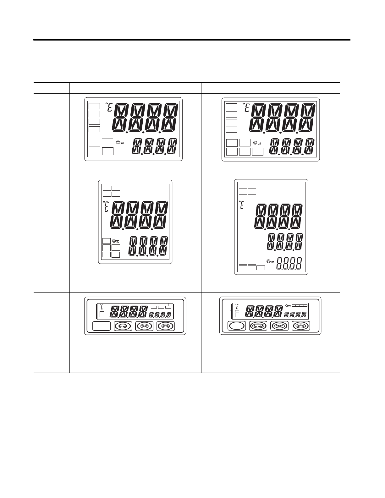
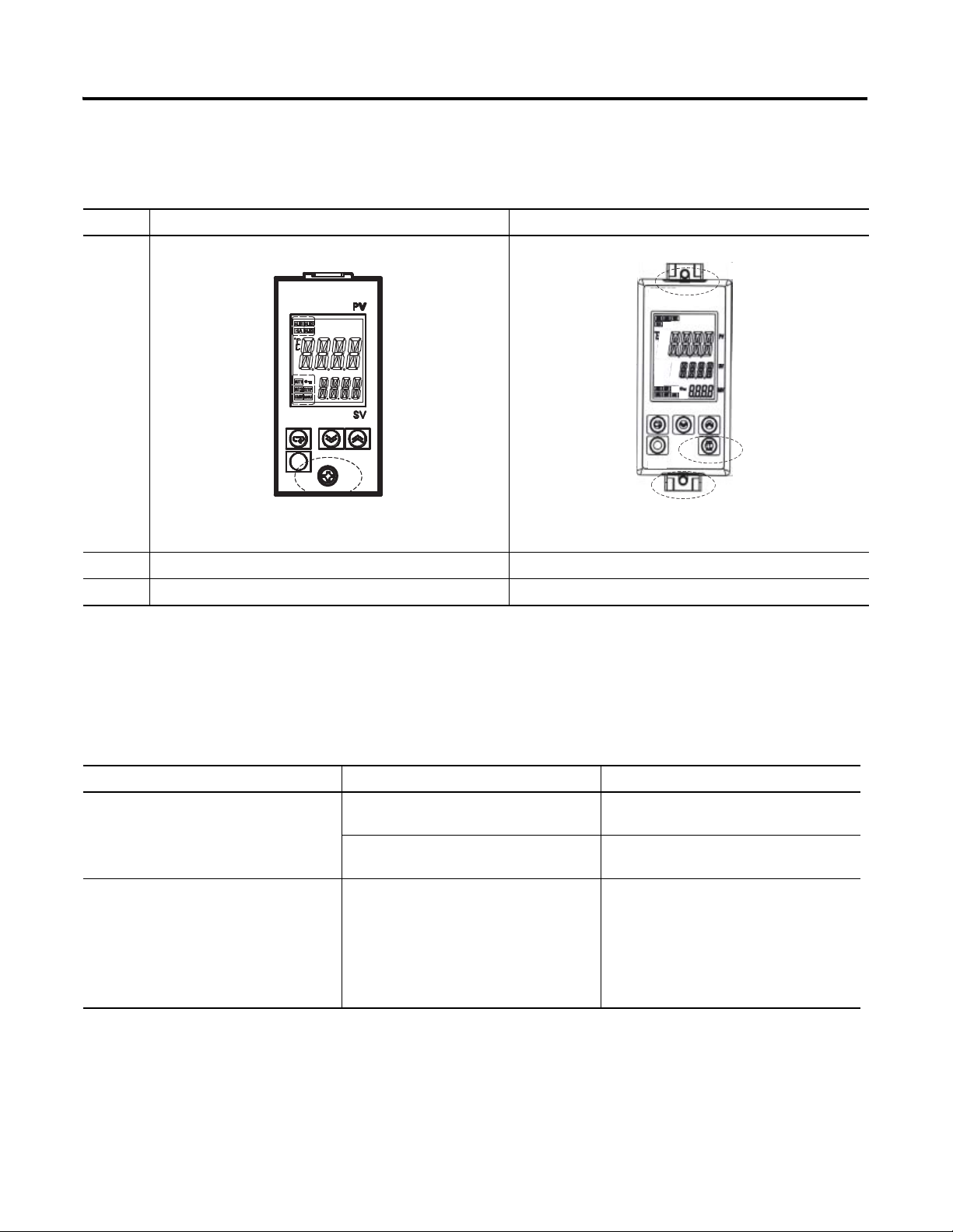
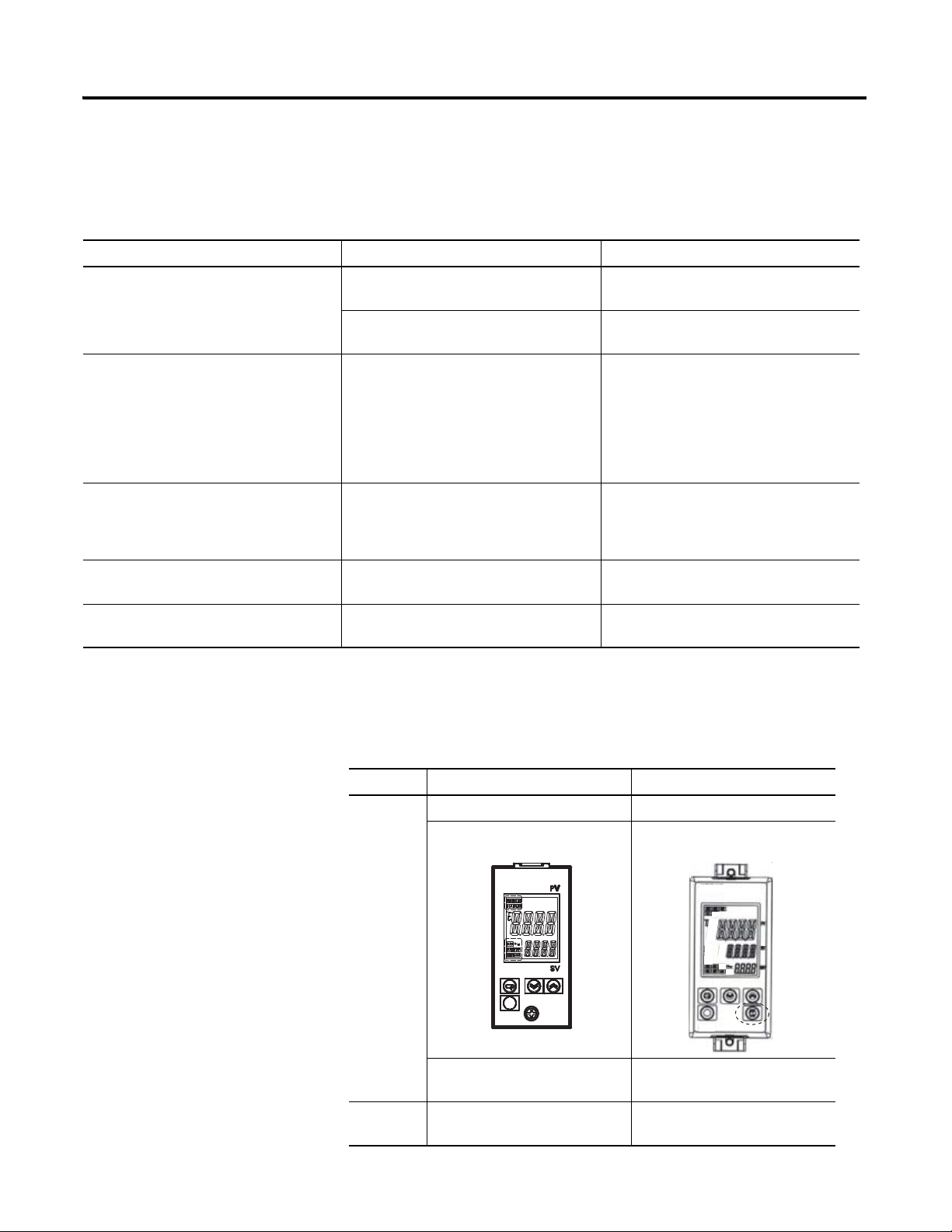
Table P.B
STOPOUT1
MANU
CMWOUT2
SUB2
SUB3
SUB1
HA
CMW STOP OUT
Preface P-iii
Series A Series B
900-TC16
900-TC8
ALM1
ALM2
ALM3
HA
OUT1
STOP
MANU
CMW
OUT2
ALM2
ALM1
HA
ALM3
OUT1
STOP
OUT2
CMW
MANU
• Number of displays: 2 (PV and SV)
ALM1
ALM2
ALM3
HA
OUT1
STOP
MANU
CMW
OUT2
• ALM indicator was changed to SUB indicator
• Number of displays: 3 (PV, SV, and MV) ➊
• ALM indicator was changed to SUB indicator.
900-TC32
• Display Segments – PV: 7 segments, SV: 7
• Character Heights – PV: 7 mm, SV: 3.5 mm
segments
CMW STOP OUT
SUB1
MANU
• Display Segments – PV: 11 segments, SV: 11
segments
• Character Heights – PV: 7.5 mm, SV: 3.6 mm
• Changes to Display Contents – “AL” LED indicator
eliminated, LED indicators and key indicator added
➊ A 2-level display is configured when shipped from the factory. A 3-level display is activated if parameters are
initialized.
Publication 900-UM007C-EN-E - January 2011
Page 18
P-iv Preface
++
−
B
+
V
mA
−
−
CT1
CT2
+
−
DO NOT
USE
DO NOT
USE
B
A
DO NOT
USE
DO NOT
USE
DO NOT
USE
One CT
Two CTs
Analog inputTC/Pt universal input
Control Output 2
Control Output 2
14
15
16
17
18
19
20
1
7
1212
1111
1010
9
8
2
4
3 5
6
InputInput
Power Power
SupplySupply
ControlControl
Output 1Output 1
AuxillaryAuxillary
Output 1Output 1
DO NOTDO NOT
USEUSE
A
B
B
Universal
TC/Pt Input
DO NOTDO NOT
USEUSE
B(+)
A(-)
RS-495
Communications
+
-
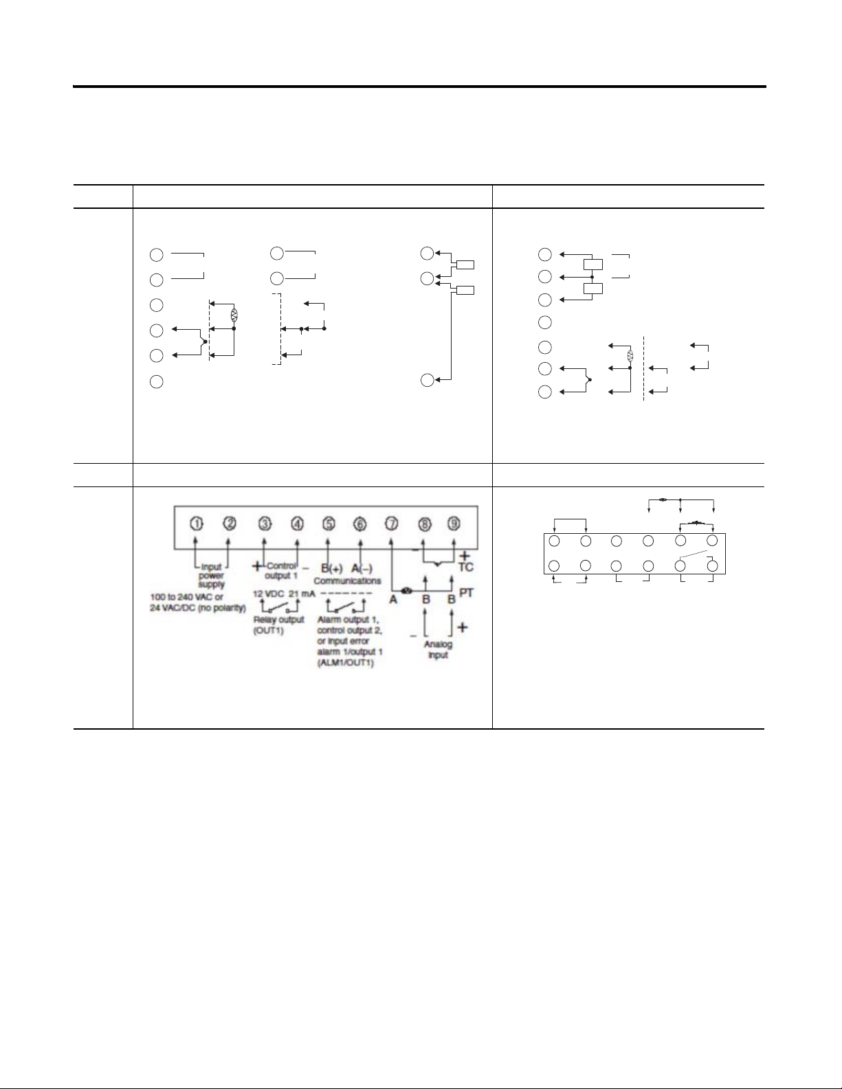
Terminal Arrangements
Table P.C — Terminal Arrangements
Series A Series B
One CT
Two CTs
14
15
19
CT1
CT2
900-TC8
Voltage output
14
Control Output 2
15
16
−
17
18
+
TC/Pt universal input
19
+
12 VDC , 21 mA
−
A
B
B
Long-life relay
output
14
Control Output 2
250 VAC, 3 A
15
(Resistive load)
−
V
+
Analog input
+
mA
−
Terminals 16...20 were changed and 1...15 were not.
900-TC16 --- No change for terminal layout
900-TC32
• 100 to 240 VAC
• 24 VAC/DC (no polarity)
Number of terminals: 9 (1 to 9)
Input terminals: 7 to 9
RS-485 communication terminals: 5 & 6
Publication 900-UM007C-EN-E - January 2011
Number of terminals: 14 (1 to 14)
Input terminals: 10 to 12
RS-485 communication terminals: 7 & 8
Page 19
Body Removal
Table P.D — Body Removal
Series A Series B
Preface P-v
• Removal using screws
900-TC8
900-TC16 --- • No change for body removal
900-TC32 --- • No change for body removal
• Removal using hooks
900-TC8, 900-TC16, &
900-TC32 Ratings
Table P.E — 900-TC8, 900-TC16, & 900-TC32 Ratings
---
Input sensor types for thermocouple inputs
Input range for E thermocouple: 0...600 ºC
• Thermocouple: ±0.5% PV or ±1ºC,
• Platinum resistance thermometer:
Input accuracy
• Analog input: ±0.5% FS ± digit
Series A Series B
whichever is greater) ±1 digit
(±0.5%PV or ±1ºC, whichever is
greater) ± 1 digit
The following types of thermocouple input
were added: W and PLII.
Input range increased for E thermocouple:
-200...600 ºC
• Thermocouple: ±0.3% PV or ±1ºC,
whichever is greater) ±1 digit
• Platinum resistance thermometer:
(±0.2%PV or ±.08ºC, whichever is
greater) ± 1 digit
• Analog input: ±0.2% FS ± digit
Publication 900-UM007C-EN-E - January 2011
Page 20
P-vi Preface
PF Key
900-TC8, 900-TC16, &
900-TC32 Ratings
Table P.E — 900-TC8, 900-TC16, & 900-TC32 Ratings
---
Input sensor types for thermocouple inputs
Input range for E thermocouple: 0...600 ºC
• Thermocouple: ±0.5% PV or ±1ºC,
• Platinum resistance thermometer:
Input accuracy
• Analog input: ±0.5% FS ± digit
Series A Series B
whichever is greater) ±1 digit
(±0.5%PV or ±1ºC, whichever is
greater) ± 1 digit
The following types of thermocouple input
were added: W and PLII.
Input range increased for E thermocouple:
-200...600 ºC
• Thermocouple: ±0.3% PV or ±1ºC,
whichever is greater) ±1 digit
• Platinum resistance thermometer:
(±0.2%PV or ±.08ºC, whichever is
greater) ± 1 digit
• Analog input: ±0.2% FS ± digit
Influence of signal source resistance
Current outputs
Alarm outputs
Characteristics
• Thermocouple: 0.1ºC/Ω (except B,
R, S), 0.2ºC/Ω (B, R, S)
• Platinum resistance thermometer:
0.4ºC/Ω
• Current output resolution, approx.:
2,700
• 250 VAC, 1A (900-TC16 & 900-TC32) • 250VAC, 3A (900-TC16)
Table P.F — Characteristics
Series A Series B
--- PV Status Display
Front Panel
(900-TC8)
• Thermocouple: 0.1ºC/Ω (for all
specifications)
• Platinum resistance thermometer:
0.1ºC/Ω
• Current output resolution, approx.:
10,000
• 250VAC, 2A (900-TC32)
PF Key Added
Publication 900-UM007C-EN-E - January 2011
---
Inputs ---
PV/SP display selection for
three-level display
Square root extraction (for models
with analog inputs)
Page 21

Table P.F — Characteristics
Series A Series B
---
Outputs
--- MV change rate limiter
--- 40% AT
Preface P-vii
Control output ON/OFF count
alarm
Communications
Characteristics
Controls
Alarms
Other ---
Table P.G
Communication
Access Size
Communication
Service
Communications
buffer size
Baud rate
Automatic cooling coefficient
---
--- PV rate of change alarm
---
Series A Series B
Double word access only
---
40 bytes 217 bytes
38.4 kbits/s max. (900-TC08, 900-TC16)
19.2 kbits/s max. (900-TC32)
adjustment for heating/cooling
control
OC alarm (only for models with
heater burnout detection)
Inverting direct/reverse operation
using event inputs or
communications commands
Word access and double
word access
Composite Read from
Variable Area and
Composite Write to
Variable Area
57.6 kbits/s max.
External
communications
RS-485/RS-232C external
communications and communications
via 900BuilderLite ™ cannot be used at
the same time.
Publication 900-UM007C-EN-E - January 2011
RS-485/RS-232C external
communications and
communications via
900BuilderLite ™ can be
used at the same time.
Page 22
P-viii Preface
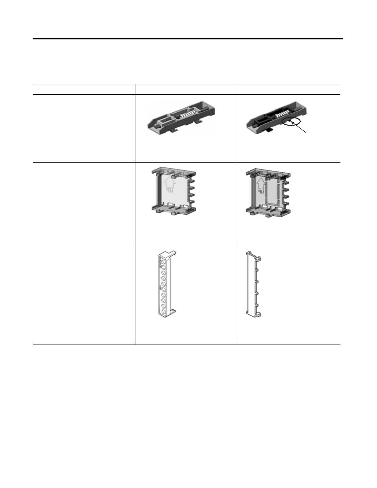
Modified section
Other Upgrades
Table P.H
Mounting Bracket
(900-TC8 only)
Terminal Cover for 900-TC16
Series A Series B
Note: The mounting bracket for the Series A
models cannot be used for Series B models.
Terminal Cover for 900-TC8
Note: The terminal covers for the Series A
models cannot be used for Series B models.
Note: The terminal covers for the Series A
models cannot be used for Series B models.
Publication 900-UM007C-EN-E - January 2011
Page 23

Preface P-ix
Option Units
(Series B Controller Compatible— One Option Unit per Controller)
This unit provides communications event input etc. functionality.
Table P.I
Bulletin No. Name Function Cat. No. (Series)
900-TC8
(Series B)
900-TC16
(Series B)
➊ Enables direct RS-232 connection to personal computer using 900BuilderLite™ software. A Cat. No. 900-CP1X cable or equivalent is
also required.
➋ Provides two event inputs. Allows selecting up to 4 different pre-configured set points, controller Run/Stop or Auto/Manual mode,
from 2 external inputs.
➌ Heater burnout is not available for 0...20 or 4…20 mA analog output style 900-TC16 controllers such as the 900-TC16AC.
➍ To obtain 57.6 k baud rate, Series B communication units must be used with any Series A or Series B 900-TC8 controller catalog
number.
➎ Series B option units must be used with Series B 900-TC16 controllers. Series A option units cannot be used with Series B controllers
and vice versa.
➏ Series B provides 57.6 K baud rate.
Communications Unit
Event Input Unit Event Input➋ 900-TC8EIM(A)
Communications and 1-Phase Heater Burnout Unit
and Heater Short
Event Input Unit with 1-Phase Heater Burnout and
Heater Short
Event Input Unit Event Input➋ 900-TC16NACEIM(B)➎
Communications Unit RS-485 communications 900-TCNACCOM(B)➎➏
Communications and 3-Phase Heater Burnout and
Heater Short Unit
Communications and Second Voltage (SSR) Output
Unit
1-Phase Heater Burnout and second voltage (SSR)
output
RS-232C communications➊ 900-TC8232 (B)➍
RS-485 communications 900-TC8COM(B)➍
RS-485 communications with
single-phase heater burnout (open) and
heater short-circuit failure detection➌
Event Input with single-phase heater
burnout (open) and heater short-circuit
failure detection➋➌
RS-485 communications with 3-phase
heater burnout (open) and heater
short-circuit failure detection
RS-485 communications and a second
voltage (SSR) output
1-Phase Heater burnout (open) and
heater short-circuit failure detection
with a second control voltage (SSR)
output
900-TC16NCOM(B)➎➏
900-TC16NEIM(B)➎
900-TC16NCOMP3(B)➎➏
900-TC16NCOMV2(B)➎➏
900-TC16P1V2(B)➎
Publication 900-UM007C-EN-E - January 2011
Page 24
P-x Preface
ABCDEFGHI JKLM
NOPQRSTUVWXYZ
Symbol
Symbol
Alphabet
Alphabet
ABCDEFGHI JKLM
NOPQRSTUVWXYZ
Symbol
Symbol
Alphabet
Alphabet
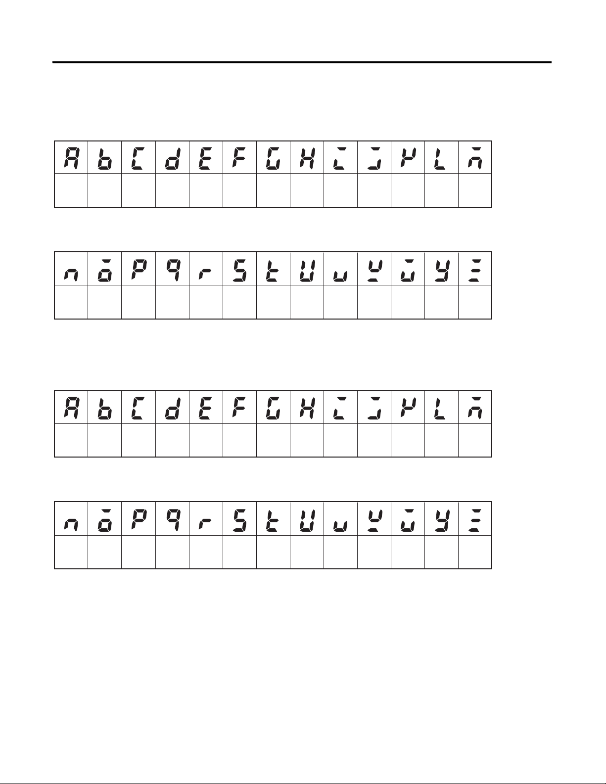
How to Read Display
Symbols
The following table shows the relationship between the symbols exhibited on
the controller’s front panel displays to alphabet characters.
Table P.J 11 — Segment Display Selection
The Character Select parameter in the Advanced Setting function group can be
turned OFF to display the following 7-segment characters.
Table P.K 7 — Segment Characters
Publication 900-UM007C-EN-E - January 2011
Page 25
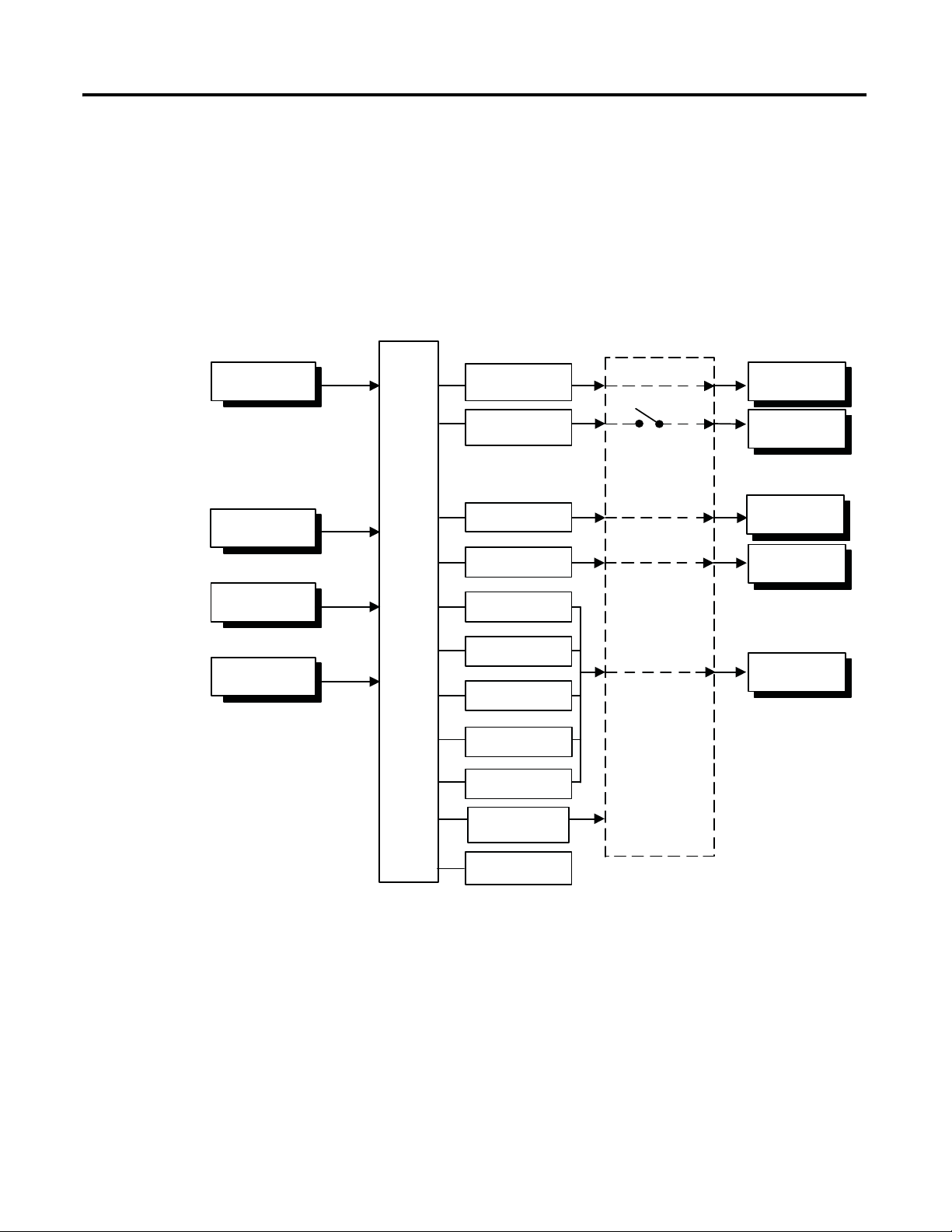
I/O Configurations & Main
Overcurrent Alarm
Temperature Input
or Analog Input
Control
Section
CT1 Input
CT2 Input
Event Inputs
2 Channels
Set point input functions
from external digital switches:
• RUN/STOP
• Program Start
• Auto/Manual
Control Output
Heating
Control Output
Cooling
Control Ouput 1
Control Ouput 2
Auxillary Output 3
Auxillary Output 2
Auxillary Output 1
Auxillary Output 3
Auxillary Output 2
Auxillary Output 1
HB Alarm
HS Alarm
Input Error
Simple Program
END Output
Communications
Function
QQ303T
Heating/Cooling
Chapter
Bulletin 900 Input & Output Overview
1
Functions
Figure 1.1 — 900-TC8 I/O Configuration
1-1 Publication 900-UM007D-EN-E - January 2011
Page 26

1-2 Bulletin 900 Input & Output Overview
Temperature Input
or Analog Input
CT1 Input
CT2 Input
Event Inputs
2 Channels
Set point input functions
from external digital switches:
• RUN/STOP
• Program Start
• Auto/Manual
Control
Section
Control Output
Heating
Control Output
Cooling
Auxillary Output 2
Auxillary Output 1
Auxillary Output 2
Auxillary Output 1
Control Ouput 1
Control Ouput 2
Heating/Cooling
Overcurrent Alarm
HB Alarm
HS Alarm
Input Error
Simple Program
END Output
Communications
Function
QQ303T
Figure 1.2 — 900-TC16 I/O Configuration
Publication 900-UM007D-EN-E - January 2011
Page 27
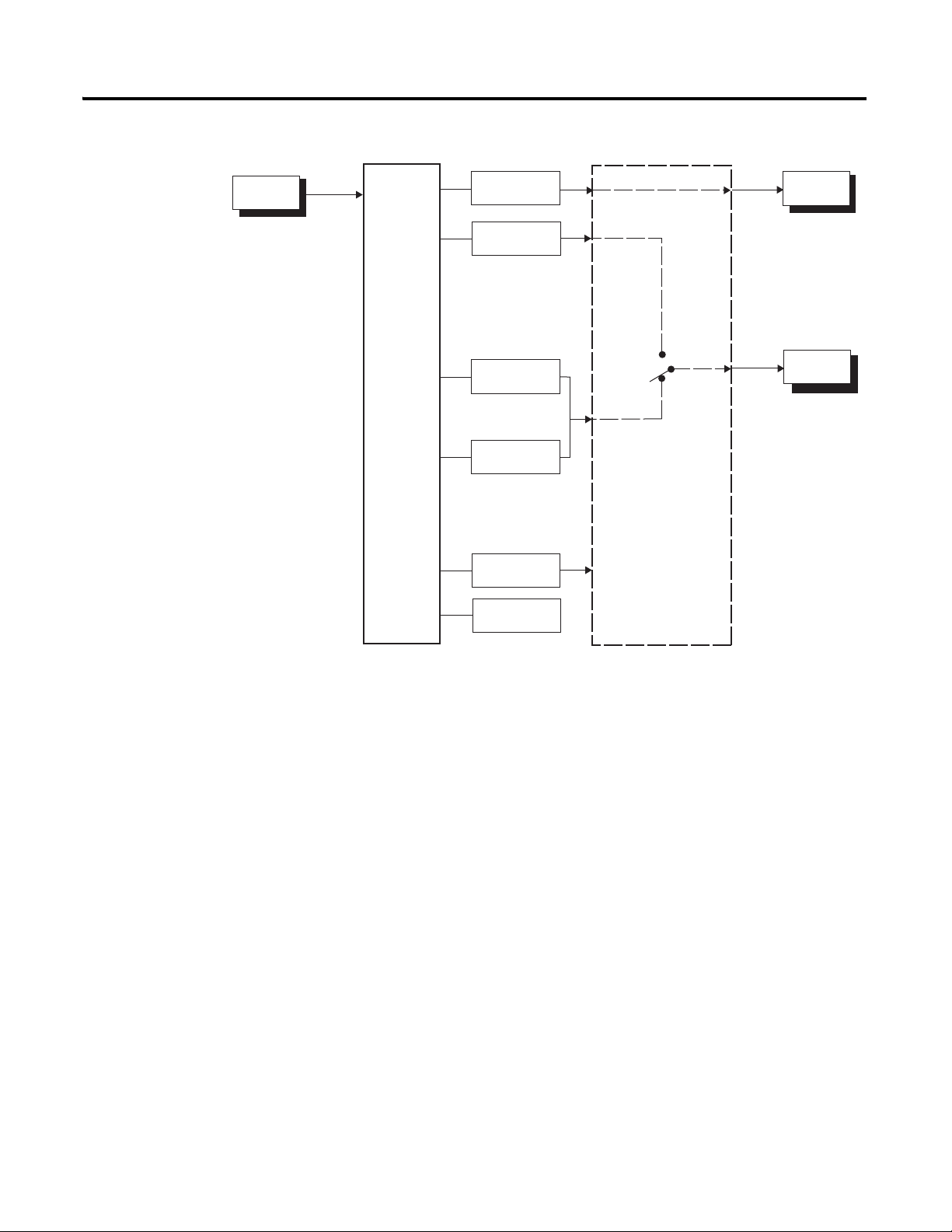
Figure 1.3 — 900-TC32 I/O Configuration
Bulletin 900 Input & Output Overview 1-3
Temperature
Input
Control
Section
Control Output
(Heating)
Control Output
(Cooling)
Alarm 1
Input Error
Program End
Output
Communications
Function
Heating/
Cooling
Standard
Control
Output 1
Auxillary
Output 1
Bulletin 900-TC8, 900-TC16, and 900-TC32 temperature controllers allow the
user to:
• Select from thermocouple and platinum RTD temperature sensors, plus
non-contact temperature sensor and analog voltage or current inputs.
➊
• Individually assign the function for each output by changing the
configured values of the following parameters: Control Output 1,
Assignment, Control Output 2 Assignment
Assignment
➊, and Aux 3 Assignment (900-TC8).
➊, Aux 1 Assignment, Aux 2
• Select heating and cooling control in addition to standard control
• Select AT (Auto-Tuning) and ST (Self-Tuning) as tuning functions
• Use multi-SP, switch between automatic and manual operation,
start/reset the simple program function, and initiate the RUN/STOP
function according to event input.
➊
• Use the Heater Burnout Alarm (HBA) and Heater Short Alarm (HSA)
function.
➊
• Use the communications function (for units equipped with the optional
communications function modules)
• Calibrate sensor input
• Configure the color of the PV display to switch between amber, red, and
green, making the process status easy to understand at a glance.
➊ The Bulletin 900-TC32 Temperature Controller does not support this function
Publication 900-UM007D-EN-E - January 2011
Page 28

1-4 Bulletin 900 Input & Output Overview
Features
• Watertight construction (equivalent to IP66 indoor use).
• Conform to cULus/IEC safety standards and EMC standards.
Main Functions
The following introduces the main functions of the Bulletin 900-TC8,
900-TC16, and 900-TC32 temperature controllers. For details on each
function and how to use them, refer to Chapter 3 and onward.
• Input Sensor Types — The following input sensors can be connected
for temperature input:
– Thermocouple: K, J, T, E, L, U, N, R, S, B, W, PL11
– Infrared non-contact temperature sensor type: Type K thermocouple
(10…70XC), K (60…120XC), K (115…165XC), K (160…260XC)
– Platinum resistance thermometer: Pt100, JPt100
– Analog millivolt input: 0…50 mV
• High level analog inputs:
– Current input:4…20 mA DC, 0 to 20 mA DC
– Voltage input:1…5V DC, 0…5V DC, 0…10V DC
• Control Output — Control output is either an On/Off
electro-mechanical relay (EMR) ON/OFF triac output (AC only)
On/Off voltage (input to solid-state relay) output, or analog current
(DC: 4...20 mA or 0…20 mA) output
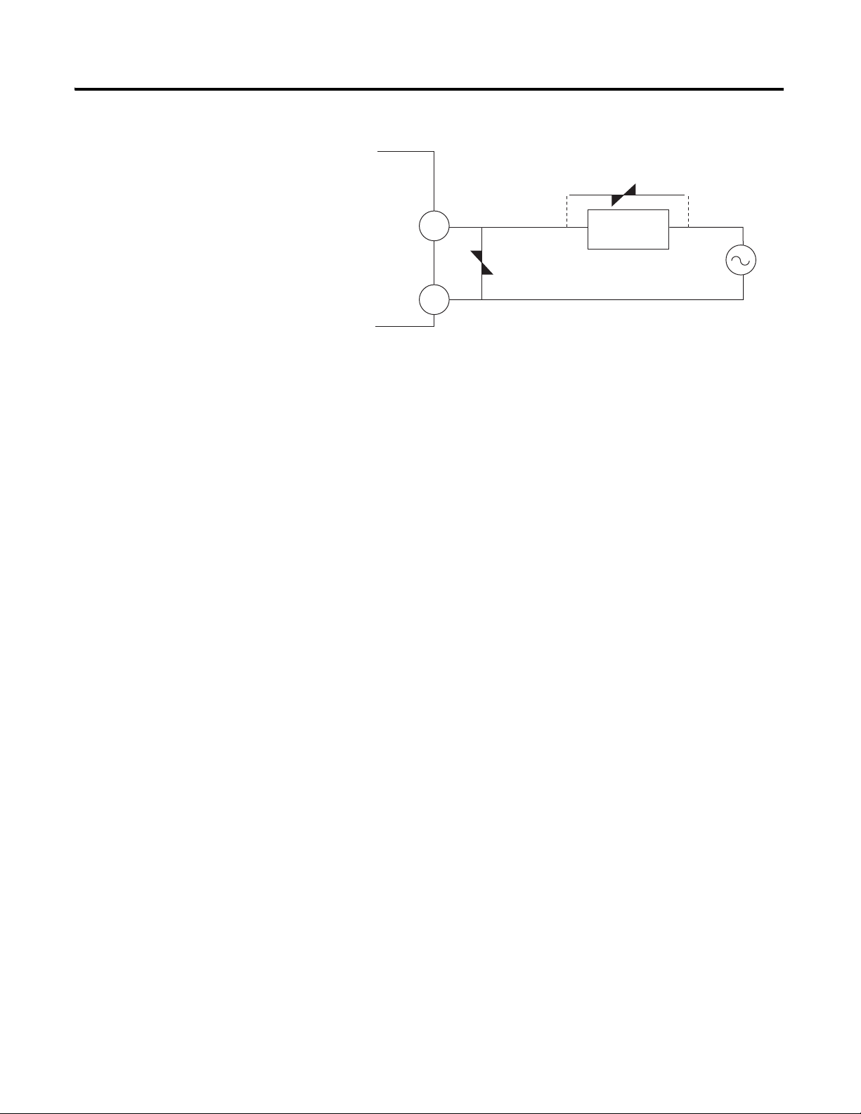
• Triac Relay Outputs
closing andopening the AC voltage circuit, thereby eliminating relay
chatter and arcing and improving durability versus an EMR. However, if
high levels of noise or surge are imposed between the output terminals,
short-circuit faults may occasionally occur. If the triac output becomes
permanently shorted, there is the danger of fire due to overheating of
the heater element. To avoid this danger, design safety into the system,
including measures to prevent excessive temperature rise and fire. Take
countermeasures such as installing a surge absorber. As an additional
safety measure, provide error detection in the control loop. Use the
Loop Break Alarm (LBA) and Heater Short Alarm (HSA) that are
provided for Bulletin 900 temperature controllers.
➊ The Bulletin 900-TC32 Temperature Controller does not support this function
➊
➊, Refer to Table 1.B or 1.D.
➊ — use semiconductors for switching when
➊,
Publication 900-UM007D-EN-E - January 2011
Page 29
Bulletin 900 Input & Output Overview 1-5
1
2
Triac
Relay Output
Varistor
Varistor
Inductive
Load
Figure 1.4 — Triac Diagram
Select a surge absorber that satisfies the following conditions.
Publication 900-UM007D-EN-E - January 2011
Page 30

1-6 Bulletin 900 Input & Output Overview
Table 1.A — Surge Absorber Selection
Voltage Used Varistor Voltage Surge Resistance
100…120V AC 240…270V
200…240V AC 440…470V
1000 A minimum
• Always connect an AC load to the triac relay output. The output will not
turn OFF if a DC load is connected.
• Alarms — Alarms are supported on the Bulletin 900 temperature
controllers. You can configure the alarm type and alarm value, or Upper
and Lower-Limit alarms.
If necessary, a more comprehensive alarm function can be achieved by
configuring the Standby Sequence, Alarm Hysteresis, Close in
Alarm/Open in Alarm and Alarm Latch ON/OFF parameters.
When the input error output is configured to ON, Alarm Output 1
turns ON when an input error occurs.
• Control Adjustment — Optimum PID constants can be configured
easily by using the AT (Auto-Tuning) and ST (Self-Tuning) parameters.
• Event Input — When the optional event input unit is mounted, the
following functions can be achieved by event input:
Multiple set point selection (multi-SP max. 4 points), RUN/STOP
mode change switching between automatic and manual operation, and
starting/stopping the simple program. Refer to Table 1.C and 1.E.
• HBA and HS Alarms — The Heater Burnout Alarm (HBA) and
Heater Short Alarm (HSA) and heater overcurrent function is
supported by selecting the appropriate controller (900-TC8) or option
module (900-TC16). Refer to Table 1.B for the TC8 and Table 1.E for
the TC16.
• Communications Function — Personal computer (PC)
communicationsare supported when the option communications unit is
mounted on the temperature controller. Refer to Table 1.C and 1.E.
Note: The PC must have 900BuilderLite software installed.
Note: 900-TC protocol is an integrated general-purpose serial
communications protocol.
Publication 900-UM007D-EN-E - January 2011
Note: Modbus is a communications control method conforming to the RTU.
Mode of Modicon Inc.'s Modbus Protocol.
Note: The 900-TC16 and 900-TC32 do not support the RS-232C interface.
Page 31

Bulletin 900 Input & Output Overview 1-7
Controller Hardware
Versions
The following tables provide a list of controller base features with associated
Cat. Nos.
Publication 900-UM007D-EN-E - January 2011
Page 32

1-8 Bulletin 900 Input & Output Overview
900-TC8
Table 1.B — Controller Versions
DIN Size
(mm)
1/8th DIN
(48 x 96 x 78)
No. of
Alarms
3
Sensor Input
Ty pe
Thermocouple
or RTD
Power
Supply
Voltage
100…240V
AC
Control
Output 1
Ty pe
Relay On/Off NA Yes (1-Phase) 900-TC8RGTH1Z25
Volts On/Off
(SSR)
Analog NA No 900-TC8ACGTZ25
Relay On/Off NA Yes (1-Phase) 900-TC8RGTH1U25
Control
Output 2
Ty pe
NA No 900-TC8RGTZ25
Volt On/Off
(SSR)
NA Yes (3-Phase) 900-TC8RGTH3Z25
NA Yes (1-Phase) 900-TC8VGTH1Z25
NA No 900-TC8VGTZ25
Triac On/Off
(3 A)
Volt On/Off
(SSR)
NA Yes (3-Phase) 900-TC8VGTH3Z25
Triac On/Off
(3 A)
Volt On/Off
(SSR)
Supports
Heater Burnout
Alarm
No 900-TC8RVGTZ25
No 900-TC8VYGTZ25
No 900-TC8VVGTZ25
No 900-TC8ACYGTZ25
No 900-TC8ACVGTZ25
Cat. No. for
Enhanced
900-TC8 Line
Analog
Current and
Voltage
Publication 900-UM007D-EN-E - January 2011
NA No 900-TC8RGTU25
24V AC/DC
100…
240V AC
Volts On/Off
(SSR)
Analog NA No 900-TC8ACGTU25
Relay On/Off NA Yes (1-Phase) 900-TC8RABH1Z25
Volts On/Off
(SSR)
Analog NA No 900-TC8ACABZ25
NA Yes (1-Phase) 900-TC8VGTH1U25
NA No 900-TC8VGTU25
NA No 900-TC8RABZ25
NA Yes (1-Phase) 900-TC8VABH1Z25
NA No 900-TC8VABZ25
Triac On/Off
(3 A)
No 900-TC8VYABZ25
Note: To implement the HBA and HSA function, a current transformer (Cat.
No. 900-CT1 or 900-CT2) is required. A current transformer is NOT
provided with the controller.
Note: When the heating and cooling function or the HBA or HSA is used,
one of the alarm outputs will be disabled for each function used.
Page 33

Table 1.C — Controller Option Units
Event Out Comms Cat. No. for Enhanced Option Units Series
— RS232 900-TC8232B B
Option Unit
— RS485 900-TC8COMB B
Yes — 900-TC8EIMA A
900-TC16
Table 1.D — Controller Versions
Bulletin 900 Input & Output Overview 1-9
DIN Size
(in mm)
1/16th DIN
Number of
Alarms
2
Sensor Input
Ty pe
Thermocouple or
RTD
Analog Current and
Voltage
Power Supply
Voltage
100…240V AC Relay On/Off 900-TC16RGTZ25
24V AC/DC Relay On/Off 900-TC16RGTU25
100…240V AC Relay On/Off 900-TC16RABZ25
24V AC/DC Relay On/Off 900-TC16RABU25
Control Output
Ty pe
Triac On/Off (3 A) 900-TC16YGTZ25
Volts On/Off (SSR) 900-TC16VGTZ25
Analog Current 900-TC16ACGTZ25
Volts On/Off (SSR) 900-TC16VGTU25
Analog Current 900-TC16ACGTU25
Triac On/Off (3 A) 900-TC16YABZ25
Volts On/Off (SSR) 900-TC16VABZ25
Analog Current 900-TC16ACABZ25
Volts On/Off (SSR) 900-TC16VABU25
Analog Current 900-TC16ACABU25
Cat. No for Enhanced
900-TC16 Line
Publication 900-UM007D-EN-E - January 2011
Page 34

1-10 Bulletin 900 Input & Output Overview
Table 1.E — Controller Option Units
DIN Size
(in mm)
1/16th DIN
Number of
Alarms
1
Heater
Burnout Event Out Comms
1-Phase HB — RS485 — 900-TC16NCOM B
— — RS485 — 900-TC16NACCOM
1-Phase HB Yes — — 900-TC16NEIM
— Yes — — 900-TC16NACEIM
3-Phase HB — RS485 — 900-TC16NCOMP3
— — RS485 Yes 900-TC16NCOMV2
1-Phase HB — — Yes 900-TC16P1V2
Voltage (SSR)
Control Output 2
Cat. No. for Enhanced
Option Units Series
➊ Series B option units must be used with Series B controllers. DO NOT use series B option units
with Series A controllers.
900-TC32
Table 1.F — Controller Versions
Sensor Input
Ty pe
Thermocouple
or RTD
Power Supply
Voltage
100…240V AC Relay On/Off Yes 900-TC32CRGTZ25
24V AC/DC Relay On/Off Yes 900-TC32CRGTZ25
Control Output
Ty pe
Volts On/Off (SSR) Yes 900-TC32CVGTZ25
Relay On/Off No 900-TC32RGTZ25
Volts On/Off (SSR) No 900-TC32CVGTZ25
Volts On/Off (SSR) Yes 900-TC32CVGTZ25
Relay On/Off No 900-TC32RGTZ25
Volts On/Off (SSR) No 900-TC32CVGTZ25
Comm Function
(RS-445)
Cat. No for Enhanced
900-TC32 Line
Publication 900-UM007D-EN-E - January 2011
Page 35

Bulletin 900 Input & Output Overview 1-11
PF
A/M
MV
SV
PV
SUB2
SUB3
STOPOUT1
MANU
CMWOUT2
SUB1
HA
Operation Indicators
Temperature Unit
Operation Indicators
Mode Key
No.1 Display
No.2 Display
No.3 Display
Up Key
Down Key
Function Key/
Auto/Manual Key
Function Group Key
Mode Key
Temperature Unit
Operation Indicators
No. 1 Display
No. 2 Display
Up Key
Function Group Key
Down Key
Front Panels & General
Functions
Figure 1.5 — Bulletin 900-TC8
Figure 1.6 — Bulletin 900-TC16
Publication 900-UM007D-EN-E - January 2011
Page 36

1-12 Bulletin 900 Input & Output Overview
SUB2
SUB3
STOPOUT1
MANU
CMWOUT2
SUB1
HA
Figure 1.7 — Bulletin 900-TC32
Display Meanings
Display Meaning
No. 1 Displays the Process Value or Parameter Type during configuration. Lights for
No. 2 Displays the Set Point, parameter operation read value, manipulated variable,
No. 3
(900-TC8 only)
approximately 1 second during startup.
or during configuration, the value of the displayed (No. 1 display) parameter.
Displays MV, soak time remaining, or multi SP. Lights for approximately 1
second during startup. A 2-level display is configured when shipped from the
factory. A 3-level display is activated if parameters are initialized.
Publication 900-UM007D-EN-E - January 2011
Page 37

Bulletin 900 Input & Output Overview 1-13
Operation Indicators 1,2,3...
Operation
Indicator Definition Function
SUB 1 Sub 1 Lights when the function configured for the Auxiliary Output 1 Assignment parameter
SUB2 Sub 2 900-TC8 and 900-TC16 Only:
SUB3 Sub 3 900-TC8 Only:
HA Heater Burnout, Heater Short Alarm, Heater
OUT1 Control Output 1 Lights when the control output function assigned to control output 1 turns ON. For a
OUT2 Control Output 2 900-TC8 and 900-TC16 Only:
STOP Operation Stopped Lights when operation is stopped. During operation, this indicator lights when
CMW Communications Writing Lights when communications writing is enabled and is not lit when it is disabled.
MANU Manual Mode Lights when the auto/manual mode is configured to manual mode.
c or f
Overcurrent Detection Output Display
Key Lights when setting change protect is ON (i.e., when the up and down Keys are
Temperature Unit The temperature unit is displayed when the display unit parameter is configured to a
is ON.
Lights when the function configured for the Auxiliary Output 2 Assignment parameter
is ON.
Lights when the function is configured for the Auxiliary Output 3 Assignment
parameter is ON.
900-TC8 and 900-TC16 Only:
Lights when a heater burnout, heater short alarm, or heater overcurrent occurs.
current output, however, OFF for a 0% output only.
Lights when the control output function assigned to control output 2 turns ON. For a
current output, however, OFF for a 0% output only.
operation is stopped by an event or by key input using the RUN/STOP function.
disabled by protected status.
temperature. Indication is determined by the currently selected Temperature Unit
parameter value. When the parameter value is configured for °C, c is displayed, and
when configured for °F, f is displayed. The display flashes during self-tuning (ST)
operation.
Publication 900-UM007D-EN-E - January 2011
Page 38

1-14 Bulletin 900 Input & Output Overview
PF
A/M
+
+
+
or
Key Definition Function
Function (Auto/Manual) 900-TC8 Only:
Function Group Select Press this key to select the desired function group. The groups are selected in the following order:
Mode Select Press this key to select the various parameters within each function group. The selection of
Basic Keypad Functions
The following describes the basic functions of the front panel keys.
This is a function key. When it is pressed for at least 1 second, the function configured in the PF
Setting parameter will operate. Example: When A-M (auto/manual) is selected in the PF Setting
parameter (initial value: A-M), the key operates as an auto/manual switch, switching between
Auto Mode and Manual Mode. If the key is pressed for more than 1 second (regardless of key
release timing), the mode will switch.
Operation function group ←→ Adjustment function group, Initial Setting function group ←→
Communications Setting function group.
parameters can be reversed by holding this key down.
Up Each press of this key increments values displayed on the No. 2 (SV) display. Holding down this
key continuously increments values.
Down Each press of this key decrements values displayed on the No. 2 (SV) display. Holding down this
key continuously decrements values.
Key Combination —
Function Group and Mode Select
Key Combination —
Function Group and Up or
Function Group and Down
This key combination settings the Bulletin 900 to the Protect function group. For details on the
Protect function group, refer to Chapter 5 , Parameter Functions & Definitions.
To restrict changing parameter values and to prevent accidental or incorrect operations, these
keys require simultaneously pressing of the key along with the or key.
The key applies only to the parameter configured for the Password to Move to Protect
function group . Refer to Chapter 5 for more detailed information on this function group.
Publication 900-UM007D-EN-E - January 2011
Page 39

Preparations
Front View Side View Back View
Allen-Bradley
900-TC8
6.0
79.2
112
20
8
8
8
Allen-Bradley
All
Br
6
Chapter
2
Hardware Installation
Approximate Dimensions
The recommended panel thickness for mounting the 900-TC16 and 900-TC32
is 1 to 5 mm and the 900-TC8 is 1 to 8 mm.
Note: Dimensions are in millimeters. Dimensions are not intended to be used
for manufacturing purposes.To convert millimeters to inches, multiply
by 0.0394.
Figure 2.1 — 900-TC8
Figure 2.2 — 900-TC16
48 4
en-
2-1 Publication 900-UM007D-EN-E- January 2011
900-TC1
44.
4.
Page 40

2-2 Preparations
48
35
24
99
44.8
22
2
1 2 3 4 5 6
7 8 9 10 11 12
(48 x number of units -2.5)
45
92
92
120 min.
➊
60 min.
Figure 2.3 — 900-TC32
Panel Cutout Dimensions
Dimensions are in millimeters. Dimensions are not intended to be used for
manufacturing purposes.
Figure 2.4 — 900-TC8
Publication 900-UM007D-EN-E - January 2011
Page 41

60
min.
45
Figure 2.5 — 900-TC16
45
Figure 2.6 — 900-TC32
x60 min.
(48 number of units -2.5)
Preparations 2-3
45
Publication 900-UM007D-EN-E - January 2011
Page 42

2-4 Preparations
ATTENTION
!
• Horizontal group-mounting of two or more temperature controllers, or
mounting temperature controllers above each other may cause heat to
build up inside the temperature controllers. This will shorten their
service life. When mounting temperature controllers like this, consider
forced cooling measures, such as a cooling fan.
• If forced air cooling is used, limit cooling to the terminal block. Rapid
variation or transients in temperature at the terminal block may result in
a measurement error.
System Wiring and Installation Guidelines
Risk of Electrical Shock
• Devices are Open Type, Listed Process Control
Equipment and must be mounted in an enclosure.
• More than one disconnect switch may be required to
de-energize the equipment before servicing.
• Signal inputs are SELV, limited energy.
• To reduce risk of fire or electrical shock, do not
interconnect the outputs of different Class 2 circuits.
• Disconnect all power (including field device) before
installing and/or servicing.
• Do not touch the controller’s wiring terminals while
the power is ON. Doing so may cause an electric
shock.
Publication 900-UM007D-EN-E - January 2011
Page 43

Preparations 2-5
ATTENTION
!
• Do not allow metal fragments or lead wire scraps to
fall inside the Bulletin 900 Controller. These may cause
electric shock, fire, or malfunction.
• Never disassemble, repair, or modify the Bulletin 900
Controller with line or field device power applied.
Doing so may cause electric shock, fire, or
malfunction.
• Do not use the Bulletin 900 Controller in flammable
and explosive gas atmospheres.
• Use the Bulletin 900 Controller within the rated supply
voltage. Not doing so may cause controller damage or
fire.
• Configure all controller settings according to the
control target of the Bulletin 900 Controller. If the
settings are not appropriate for the control target, the
controller may operate in an unexpected manner,
resulting in damage to the product or personal injury.
• To maintain safety in the event of a product
malfunction, always take appropriate safety measures,
such as installing an alarm on a separate line to prevent
excessive temperature rise. If a malfunction prevents
proper control, an accident may result.
• Do not wire unused terminals.
• Make sure to observe correct polarity when wiring the
controller terminals.
• Power supply, input, output, and communication
terminals (for models with communications) have
basic insulation between them.
When double insulation is required, apply
supplemental insulation defined in IEC 60664 that is
suitable for the maximum operating voltage with
clearances or solid insulation.
Publication 900-UM007D-EN-E - January 2011
Page 44

2-6 Preparations
ATTENTION
!
• Do not use the Bulletin 900 Controller in the following
places which might exceed its specifications:
– Places subject to dust or corrosive gases (in
particular, sulfide gas, and ammonia gas)
– Places subject to high humidity, condensation, or
freezing
– Places subject to direct sunlight
– Places subject to vibration and large shocks
– Places subject to splashing liquid or oily atmosphere
– Places directly subject to heat radiated from heating
equipment
– Places subject to intense temperature changes
• To allow heat to escape, do not block the area around
the Bulletin 900 Controller. Ensure that enough space
is left for the heat to escape. Do not block the
ventilation holes on the casing.
• Cleaning: Do not use paint thinner or the equivalent.
Use standard grade alcohol to clean the Bulletin 900
Controller.
• Use within the following temperature and humidity
ranges:
Temperature: –10…+55 °C
Humidity: 25…85% (with no icing or condensation)
If the Bulletin 900 Controller is installed inside a
control panel, the ambient temperature must be kept to
under 55 °C, including the temperature around the
controller.
If the Bulletin 900 Controller is subjected to heat
radiation, use a fan to cool the surface of the controller
to under 55 °C.
• Never place heavy objects on, or apply pressure to the
Bulletin 900 Controller as it may cause it to deform and
deteriorate during use or storage.
Publication 900-UM007D-EN-E - January 2011
Page 45

ATTENTION
!
• Store within the following temperature and humidity
Upper Panel
Mounting
Adaptor
Gasket material for
NEMA 4X (waterproof)
material
Lower Panel
Mounting
Adaptor
Control
Panel
ranges:
Temperature: –25…+65 °C
Humidity: 25…85% (with no icing or condensation)
• Avoid using the Bulletin 900 Controller in places near a
radio, television configured, or wireless installation.
These devices can cause radio disturbances which may
adversely affect the performance of the Bulletin 900
Controller.
Panel Mounting — 900-TC8
How to Attach the Bulletin 900-TC8 on the Panel
Preparations 2-7
Figure 2.7 — 900-TC8
1. If water-proofing is required, ensure the gasket material is inserted
between the front of the controller’s case and the control panel.
2. Insert the Bulletin 900-TC8 into the mounting hole in the panel
(1…8 mm panel thickness).
3. Pull the upper and lower panel mounting adapters along the
Bulletin 900-TC8 body from the rear of the case up to the panel, and
fasten temporarily.
Publication 900-UM007D-EN-E - January 2011
Page 46

2-8 Preparations
4. Tighten the upper and lower adapter mounting screws alternately with
only one turn of the screwdriver at a time to maintain an even torque
balance. Tighten the screw until the ratchet mechanism operates.
5. To allow heat to escape, do not block the area around the
Bulletin 900-TC8 Temperature Controller. (Ensure that enough space is
left for the heat to escape.) Do not block the ventilation holes on the
casing.
6. Allow as much space as possible between the Bulletin 900-TC8 and
devices that generate powerful high-frequency noise (e.g.,
high-frequency welders, high-frequency sewing machines) or surges.
7. Install the controller so that it is horizontal (can read the display
properly).
Note: When group mounting two or more Bulletin 900-TC8s, make sure that
the surrounding temperature does not exceed the allowable operating
temperature given in the specifications.
Mounting the Terminal Cover
To attach the terminal cover to the terminal block, slightly bend the terminal
cover, as shown below. The terminal cover cannot be attached in the opposite
direction.
Figure 2.8 — 900-TC8 Mounting the Terminal Cover
Enlarged Illustration of Terminal Section
Slightly bend the
terminal cover
in the direction shown
by the arrows.
Publication 900-UM007D-EN-E - January 2011
Page 47

Preparations 2-9
IMPORTANT
900-TC8 (Series B) Case Removal while Panel-Mounted
The control unit can be removed from its case whether or not it is mounted on
the control panel. This allows you to perform maintenance or to add option
units without opening the control panel enclosure or removing the terminal
compartment.
Figure 2.9 — 900-TC8 (Series B) Case Removal while Panel-Mounted
Tool Insertion
Holes
(1)
(2)
(3)
(1)
Top View
Rear
Case
Front
Panel
Gap
Flat-blade Screwdriver
(Unit: mm)
2.00.4 5.0
Ensure controller and I/O power is OFF before removing
the internal mechanism. When you remove the internal
mechanism from the housing, never touch electric
components inside or subject the internal mechanism to
shock.
1. Insert a flat-blade screwdriver into the two tool insertion holes (one on
the top and one on the bottom) to release the hooks.
2. Insert the flat-blade screwdriver in the gap between the front panel and
the rear case (two on the top and two on the bottom), and use it to pry
and pullout the front panel slightly. Then, pull out on the front panel
gripping both sides. Be sure not to impose excessive force on the panel.
Setting Up the 900-TC8 Controller with the Optional Units
If RS-232, RS-485 communications inputs are required, mount the RS-232
communications unit (Cat. No. 900-TC8232), the RS-485 communications
unit (Cat. No. 900-TC8COM), or the event input unit (Cat. No.
900-TC16EIM) in the Bulletin 900-TC8 controller. These units provide optical
isolation (approx. 32V DC) between the controller electronics and field input.
Publication 900-UM007D-EN-E - January 2011
Page 48

2-10 Preparations
(1)
(3)
(2)
Location for Boards:
900-TC8EIM: Event Input
900-TC8232: RS-232
900-TC8COM: RS-485
Table 2.A
Name Cat. No.
(Series)➊
Communications board 900-TC8COM (B) RS-485 Communications support
900-TC8232 (B) RS-232 Communications support
Event input unit 900-TC8EIM (A) Event input support
➊ One (1) unit per controller. This series of option units are compatible with Series A or Series B controllers.
Function
Panel Mounting — 900-TC16
How to Attach the Bulletin 900-TC16 on the Panel
To prevent electrostatic damage to the board, make sure you are properly
grounded before installing it. Follow the steps below.
Figure 2.10
Publication 900-UM007D-EN-E - January 2011
1. Insert the controller through the hole in the panel from the front, and
push the panel mounting adapter on from the rear. Push the adapter up
to the back of the panel ensuring that the controller is pushed all the way
in, removing any gap between the controller, panel, and adapter. Finally,
use the two screws on the adapter to secure the unit in place. The
recommended panel thickness is 1…5 mm.
2. To mount the Bulletin 900-TC16 so that it is waterproof, insert the
waterproof packing on the Bulletin 900-TC16. The Bulletin 900-TC16
cannot be waterproofed when it is group-mounted in the horizontal
fashion.
3. Maintain the specified mounting space between each controller.
Page 49

Preparations 2-11
Panel
Safety Terminal
Block Cover
Rear Case
Terminal Block
Panel Mounting
Adaptor
Front Case
4. Tighten the two screws on the adapter against the panel. Tighten the
two screws alternately keeping the torque to approximately
0.29…0.39 N•m (2.57…3.45 lb-in.).
5. To allow heat to escape, do not block the area around the
Bulletin 900-TC16 Temperature Controller. (Ensure that enough space
is left for the heat to escape.) Do not block the ventilation holes on the
casing.
6. Allow as much space as possible between the Bulletin 900-TC16 and
devices that generate powerful high-frequency noise (e.g.,
high-frequency welders, high-frequency sewing machines) or surges.
7. Install the controller so that it is horizontal (can read the display
properly).
How to Attach the 900-TC16 Wiring Terminal Block Cover
Figure 2.11
Make sure that the UP mark on the adapter is facing up, and then fit the
terminal cover into the holes on the top and bottom. The Bulletin 900-TC16 is
provided with a protective terminal block cover (finger protection per
VDE 0106).
Setting Up the 900-TC16 Controller with the Optional Units
If RS-485 communications, Event Input, second Control Output, or Heater
Burnout functions are required, mount the appropriate option unit in the
Bulletin 900-TC16 controller.
900-TC16 Option Units
Table 2.B below provides the list of available options.
Publication 900-UM007D-EN-E - January 2011
Page 50

2-12 Preparations
(1)
(1)
(2)
(4)
(3)
20 min.
Flat-blade Screwdriver
Units: mm
Table 2.B
Function 900-TC16 Option
Module Cat.
Heater Burnout
& Heater Short
Event
Input
Comms.
Voltage (SSR)
Control Output 2
No.(Series)
➊➋
1-Phase HB — RS485 — 900-TC16NCOM (B)
— — RS485 — 900-TC16NACCOM (B)
1-Phase HB Yes — — 900-TC16NEIM (B)
— Yes — — 900-TC16NACEIM (B)
3-Phase HB — RS485 — 900-TC16NCOMP3 (B)
— — RS485 Yes 900-TC16NCOMV2 (B)
1-Phase HB — — Yes 900-TC16P1V2 (B)
➊ One (1) option unit per controller.
➋ The option unit provides optical isolation (approximately 32V DC) between the controller electronics and the
field input. Series B option units must be used with Series B controllers and vice versa.
Installing the Option Unit/Board in the Controller
Figure 2.12
Note: When you remove the internal mechanism from the housing, never
touch electric components inside or subject the internal mechanism to
shock.
Publication 900-UM007D-EN-E - January 2011
Page 51

Panel Mounting — 900-TC32
Mounting to the Panel
Figure 2.13
Preparations 2-13
Note: For waterproof mounting, waterproof packing must be installed on the
controller. Waterproofing is not possible when group mounting several
controllers. Waterproof packing is not necessary when there is no need
for the waterproofing function.
1. For waterproof mounting: Install waterproof packing on the
controller.
2. Insert the 900-TC32 into the mounting hole in the panel.
3. Push the adapter from the terminals up to the panel, and temporarily
fasten the 900-TC32
4. Tighten the two fastening screws on the adapter. Alternately tighten the
two screws little by little to maintain a balance. Tighten the screws to a
torque of 0.29 to 0.39 N·m.
Publication 900-UM007D-EN-E - January 2011
Page 52

2-14 Preparations
The body of the controller can be replaced by removing the terminal block
from the 900-TC32.
Figure 2.14
1. Insert a flat-blade screwdriver into the tool holes (one on the top and
one on the bottom) to release the hooks. Do not apply excessive force.
2. Pull the terminal block out while the hooks are released.
Publication 900-UM007D-EN-E - January 2011
Page 53

Bulletin 900 Wiring
Input power supply
Auxiliary output 2
1
2
3
4
5
13
14
15
6
7
8
9
10
16
17
18
19
Control output 1
Analog input
TC/Pt universal input
B
V
mA
Auxiliary output 3
20
CT1
CT2
EV1
EV2
CT1/CT2 Control Output 2
+
-
Control output 2
DO NOT
USE
DO NOT
USE
B
A
DO NOT
USE
DO NOT
USE
DO NOT
USE
Auxiliary output 1
Event Inputs
11
12
A heater burnout alarm, heater short alarm,
heater overcurrent alarm, or input alarm is
sent to the output to which the alarm 1
function is assigned.
250 VAC, 3 A
(resistive load)
Relay outputs
Auxiliary output
1, 2, 3
• 100 to 240 VAC
• 24 VAC/VDC (no polarity)
Current output
0 to 20 mA DC
Voltage output
(for driving SSR)
12 VDC, 40 mA
Load: 600 Ω max.
4 to 20 mA DC
Relay output
250 VAC, 5A
(resistive load)
Control output 2
Voltage output
(for driving SSR)
12 VDC, 21 mA
Control output 1
Triac output
250 VAC, 3 A
(resistive load)
Communications
900-TC8COM
RS-485
B (+)11
12
DO NOT USE13
900-TC8232
RS-232C
SD11
RD12
SG13
900-TC8EIM
Event inputs
11
12
13
EV
EV2
CT1/CT2
Option Units
CT1 CT1
EV2
EV1
11
12
13
14
15
11
12
13
14
15
11
12
13
14
15
11
12
13
14
15
B
A
RS-485
B
A
+
RS-485
CT1
CT2
15
14
12
13
11
5
4
A
B
B
mA
V
+
+
−
−
6
8
9
10
2
3
1
7
+
+
−
+
−
Relay output
250V AC, 3 A
(Resistive load)
Voltage output
12V DC, 21 mA
Current output
4 to 20 mA DC
0 to 20 mA DC
Load 600 Ω max.
Analog input TC/Pt
Multi-input
Control output 1
Auxiliary output (Relay output)
Auxiliary output 2
Input power supply
100 to 240V AC
24V AC/DC (no polarity)
900-TC16NEIM
900-TC16NCOMP3
900-TC16NCOMV2
900-TC16PIV2
Voltage output
12V DC, 21 mA
Control Output 2
Control Output 2
Auxiliary output 1, HBA/HS
alarm/input error
Do not
connect.
Do not
connect.
CT1
11
12
13
14
15
+
−
Do not
connect.
900-TC16NCOM
EV2
EV1
11
12
13
14
15
900-TC16NACEIM
Auxiliary output (Relay
output), 250V AC, 1 A
(Resistive load)
B
A
RS-485
11
12
13
14
15
+
−
Do not
connect.
900-TC16NACCOM
B
A
RS-485
Preparations 2-15
Terminals
Figure 2.15 — 900-TC8 (Series B) Terminal Arrangement
Figure 2.16 — 900-TC16 Terminal Arrangement
Publication 900-UM007D-EN-E - January 2011
Page 54

2-16 Preparations
1
7
1212
1111
1010
9
8
2
4
3 5
6
InputInput
Power Power
SupplySupply
ControlControl
Output 1Output 1
AuxillaryAuxillary
Output 1Output 1
DO NOTDO NOT
USEUSE
A
B
B
Universal
TC/Pt Input
DO NOTDO NOT
USEUSE
B(+)
A(-)
RS-495
Communications
+
-
Relay Output 250 VAC, 2 A
(resistive load)
Voltage Output
12 VDC, 21 mA
(for driving SSR)
Relay Output 250 VAC, 2 A
(resistive load)
Control Output 1
Auxillary Output 1
Figure 2.17 — 900-TC32 Terminal Arrangement
Publication 900-UM007D-EN-E - January 2011
Page 55

Preparations 2-17
ATTENTION
!
Wiring Guidelines and Precautions
• Do not wire unused terminals.
• Make sure to observe correct polarity when wiring the
controller terminals.
• To reduce induction noise, separate the high-voltage or
large-current power lines from other lines, and avoid
parallel or common wiring with the power lines when
you are wiring to the terminals. We recommend using
separating pipes, ducts, or shielded lines.
• Allow as much space as possible between the
Bulletin 900 Controller and devices that generate
powerful high-frequency noise (e.g., high-frequency
welders, high-frequency sewing machines) or surges.
• Separate input leads and power lines in order to protect the
Bulletin 900-TC8, 900-TC16, 900-TC32, and its low voltage sensors
(e.g., thermocouple) lines from external noise.
• For 900-TC32: Use a shielded AWG24 to AWG18 (cross-sectional area
of 0.205 to 0.823 mm2) twisted-pair cable. The stripping length is
6 to 8 mm.
• We recommend using solderless lugs when wiring to the
Bulletin 900-TC8 and 900-TC16 screw terminals. However, if lugs are
not used, the controller’s screw terminals will accept two solid or
stranded wires (no mixing) between 24 (0.205 mm
2
mm
)AWG. Wire strip length 5...6 mm.
• For 900-TC8 & 900-TC16: Tighten the terminal screws properly.
Tighten them to a torque 0.74…0.9 N•m (6.6…8 lb-in.) Loose screws
may cause malfunction. For 900-TC32: Tighten the terminal screws to a
torque of 0.5 N•m
• Use the type of solderless lugs referenced in Figure 2.18 for your proper
Bulletin type.
2
)...14 (2.081
Publication 900-UM007D-EN-E - January 2011
Page 56

2-18 Preparations
ATTENTION
!
Figure 2.18 — Wiring
7.2 mm max.
7.2 mm max.
Wiring
Power Supply
The controller requires an external power source for operation. For the
900-TC8 connect to terminals 1 and 2 and for the 900-TC16 connect to
terminals 9 and 10. The following table shows the specifications.
Table 2.C
Input Power Supply Bulletin 900-TC8 Bulletin 900-TC16
100…240V AC, 50/60 Hz 10VA 7.5VA
24V AC, 50/60 Hz 5.5VA 5VA
24V DC (not polarity sensitive) 4 W 3 W
Use a power supply matched to the power specifications of
the Bulletin 900 Controller. Also, make sure that rated
voltage is attained within 2 seconds of turning the power
ON.
Publication 900-UM007D-EN-E - January 2011
Page 57

Preparations 2-19
When mounting a noise filter on the power supply, make sure to first check the
filter’s voltage and current capacity, and then mount the filter as close as
possible to the Bulletin 900 Controller. Reinforced insulation is applied to the
power supply I/O sections.
Wiring Input/Sensor Devices
Connect sensors to the terminals as follows according to the Input Type and
controller.
3
4
5
Thermocouple
900-TC16 Input Sensor Wiring
18
19
20
Thermocouple
900-TC8 Input Sensor Wiring
3
−
4
5
+
Platinum resistance
thermometer
18
−
19
20
+
Platinum resistance
thermometer
3
4
5
Analog input
18
19
20
Analog input
+
mA
−
−
V
+
+
mA
−
−
V
+
Input/Sensor Wiring Considerations
• When the thermocouple leads are extended, make sure to use shielded
thermocouple extension wire matched to the type of thermocouple.
• For a thermocouple, make sure to follow the polarity color code convention.
• If there is a large error in the measurement values, make sure that the correct
sensor type is configured and for thermocouples that input compensation has
been properly configured.
• RTDs can be either 2- or 3-wire types. If a 3-wire type is used, the controller
provides lead wire resistance compensation up to 5 Ω resistance. If using 24
AWG lead wire, this is approximately 59 m of wire. Use larger gauge wire if
longer length is required.
• For RTDs, the controller source is approximately 1 mA of current.
• If a cooling fan is used in the panel enclosure, prevent only the terminal
block from being cooled when using thermocouples. Otherwise, this may
result in a measurement error.
Publication 900-UM007D-EN-E - January 2011
Page 58

2-20 Preparations
900-TC16 Control Output 1
1
2
1
2
L
+
−
GND
+V
+
−
−
1
2
+
+V
L
Relay Voltage (SSR) Analog Current
L
+
v
+
−
900-TC8 Control Output 1
Relay Voltage (SSR) Analog Current
+
v
L
+
−
GND
+
v
L
+
−
900-TC32 Control Output 1
• To reduce induced electrical noise, the leads on the temperature controller’s
terminal block must be wired separately from large-voltage/large-current
power leads. Also, avoid wiring leads in parallel with power leads or in the
same wiring path. Other methods such as separating conduits and wiring
ducts, or using shield wire are also effective and recommended.
Wiring Control Output 1
The following diagrams show the available outputs and their internal
equalizing circuits.
Figure 2.19
Publication 900-UM007D-EN-E - January 2011
Page 59

Preparations 2-21
The following tables show the specifications for each output type.
Table 2.D — 900-TC8
Output Type Output 1 Specifications
Relay 250V AC, 5 A (resistive load), electrical durability: 100,000
operations
Voltage (PNP) PNP type, 12V DC +15%/−20%, 40 mA (with short-circuit
protection). Series B 12V DC ± 15%.
Current DC 4… 20 mA/DC 0…20 mA, resistive load: 600 Ω max.
Resolution: Approx.10,000
Table 2.E — 900-TC16
Output Type Output 1 Specifications
Relay 250V AC, 3 A (resistive load), electrical durability: 100,000
operations
Triac (AC) relay 250V AC, 3 A (resistive load), electrical durability: 1,000,000
operations
Voltage (PNP) PNP type, 12V DC ±15%, 21 mA (with short-circuit protection)
Current DC 4…20 mA/DC 0…20 mA, resistive load: 600 Ω max.
Resolution: Approx. 10,000
Table 2.F — 900-TC32
Output Type Output 1 Specifications
Relay 250V AC, 2 A (resistive load), electrical durability: 100,000
operations
Voltage (PNP) PNP type, 12V DC ±15%, 21 mA (with short-circuit protection)
Publication 900-UM007D-EN-E - January 2011
Page 60

2-22 Preparations
Output Wiring Considerations
• Do NOT connect a DC load to the Triac (AC) relay.
• The PNP voltage (SSR) output (Control Output 1) is not electrically
isolated from the controller’s internal circuits. SSR Control Output 2 of
the 900-TC16 is also not isolated. However, SSR Control Output 2 of
the 900-TC8 is isolated. When using a grounded thermocouple, do not
connect any control output terminals to earth ground. If the control
output terminals are connected to earth ground, errors will occur in the
measured temperature values as a result of ground loop leakage current.
• For 900-TC8 & 900-TC16: The 4...20 and 0…20 mA analog output is
electrically isolated from the other controller circuits as follows:
– Analog Output to Sensor Input: 500V AC 50/60 Hz for 1 minute
– Analog Output to Alarm Output: 2000V AC 50/60 Hz for 1 minute
– Analog Output to Input Power Supply: 2000V AC 50/60 Hz for 1
minute
• The life expectancy of the electro-mechanical relay outputs vary greatly
with the switching capacity and other switching conditions. Always use
the output relays within their rated load and electrical life expectancy. If
an output relay is used beyond its life expectancy, its contacts may
become fused or burned.
• Use the Bulletin 900 Controller within the rated load. Not doing so may
cause damage or fire.
• Attach a surge suppressor or noise filter to peripheral devices that
generate noise (in particular, motors, transformers, solenoids, magnetic
coils, or other equipment that have an inductance component).
• About 4 seconds are required for control and/or alarm outputs to turn
ON when the power is initially turned ON to the controller. Take this
into consideration when the temperature controller is incorporated into
a sequence circuit.
• For 900-TC8 & 900-TC16: Triac (AC) relay outputs use
semiconductors for switching when closing and opening the circuit,
thereby eliminating relay chatter and arcing and improving durability
compared to an electro-mechanical relay output. However, if high levels
of electrical noise or surge are imposed between the output terminals,
short-circuit faults may occasionally occur. If the output becomes
permanently shorted, there is the danger of fire due to overheating of
the heater. Design safety into the system, including measures to prevent
excessive temperature rise and fire. Take countermeasures such as
installing a surge absorber. As an additional safety measure, provide
error detection in the control loop. (Use the Loop Burnout Alarm
Publication 900-UM007D-EN-E - January 2011
Page 61

Preparations 2-23
1
2
Triac (AC)
relay output
Varistor
Varistor
Inductive
load
+
v
L
+
v
L
+
v
L
900-TC8 Control Output 2
Relay Voltage
GND
Voltage Voltage
900-TC16 Control Output 2
or
GND
GND
➊
➋
(LBA) and Heater Short Alarm (HSA) that are provided for the Bulletin
900 Controller.)
Figure 2.20
Select a surge absorber that satisfies the following conditions.
Table 2.G
Voltage Used Varistor Voltage Surge Resistance
100…120V AC 240…270V 1,000 A min.
200…240V AC 440…470V
Control Output 2
• For 900-TC8 & 900-TC16: Output 2 is applied from terminals 11 and
12 or 14 and 15 with the 900-TC16, and from pins 14 and 15 with the
900-TC8. The following diagrams show the available outputs and their
equal internal circuits.
Figure 2.21
➊ Option Unit: 900-TC16P1V2
➋ Option Unit: 900-TC16NCOMV2
The following table shows the specifications for each output type.
Table 2.H — 900-TC8
Output Type Output 2 Specifications
Triac (AC) relay 250V AC, 3 A (resistive load), electrical durability: 1,000,000
operations
Voltage (PNP) PNP type, 12V DC +15%/−20%, 21 mA (with short-circuit
protection)
Publication 900-UM007D-EN-E - January 2011
Page 62

2-24 Preparations
Table 2.I — 900-TC16
Output Type Output 2 Specifications
Voltage (PNP) PNP type, 12V DC ±15%, 21 mA (with short-circuit protection)
• Always connect an AC load to a Triac (AC) relay output. The output will
not turn OFF if a DC load is connected.
• A voltage output (control output) is not electrically isolated from the
internal circuits. Therefore, when using a grounded thermocouple, do
not connect any of the control output terminals to earth ground. If
control output terminals are connected to ground, errors will occur in
the measured temperature values as a result of ground loop leakage
current. With 900-TC8, however, voltage output (Control Output 2) is
functionally isolated from the internal circuits.
• Control Output 2 of the 900-TC16 is a voltage output (SSR driver) only,
and outputs across terminals 11(+) and 12(-), or 14(+) and 15(-).
• Control outputs 1 and 2 (voltage outputs) are not isolated.
• Triac (AC) relay outputs use semiconductors for switching when closing
and opening the circuit, thereby eliminating relay chatter and arcing and
improving durability compared to an electro-mechanical relay output.
However, if high levels of electrical noise or surge are imposed between
the output terminals, short-circuit faults may occasionally occur. If the
output becomes permanently shorted, there is the danger of fire due to
overheating of the heater. Design safety into the system, including
measures to prevent excessive temperature rise and fire. Take
countermeasures such as installing a surge absorber. As an additional
safety measure, provide error detection in the control loop. (Use the
Loop Burnout Alarm (LBA) and Heater Short Alarm (HSA) that are
provided for the Bulletin 900.)
Figure 2.22
Triac (AC)
relay output
1
Varistor
2
Varistor
Inductive
load
Publication 900-UM007D-EN-E - January 2011
Page 63

Preparations 2-25
Select a surge absorber that satisfies the following conditions.
Table 2.J
Voltage Used Varistor Voltage Surge Resistance
100…120V AC 240…270V 1,000 A min.
200…240V AC 440…470V
Wiring Auxiliary Outputs (1, 2, and 3)
• On the 900-TC8, Auxiliary Output 1 (SUB1) is output across terminals
9 and 10, Auxiliary Output 2 (SUB2) is output across terminals 7 and 8,
and Auxiliary Output 3 (SUB3) is output across terminals 5 and 6.
• When the HBA or the HS Auxiliary is used with the 900-TC8,
Auxiliaries are output across terminals 9 and 10.
• On the 900-TC8, when heating/cooling control is used, Auxiliary
Output 3 becomes control output (cooling).
• On the 900-TC16, Auxiliary Output 1 (SUB1) is output across terminals
7 and 8, and Auxiliary Output 2 (SUB2) is output across terminals 6
and 8.
• On the 900-TC32, Auxiliary Output 1 (SUB1) is output across terminals
5 and 6.
• On the 900-TC32, when heating/cooling control is used, auxiliary
output 1 becomes control output (cooling).
• When the HB, the HS, or heater overcurrent alarm is used with the
900-TC16, alarms are output across terminals 7 and 8.
• On the 900-TC16, when heating/cooling control is used, Auxiliary
Output 2 becomes control output (cooling).
• When the Input Error Output parameter is configured to ON, the
output assigned to Alarm Output 1 turns ON when an input error
occurs.
• For models that have a Heater Burnout Alarm (not supported by
900-TC32), an OR of the alarm 1 function and the HB/HS or heater
overcurrent alarm is sent to the output assigned to the alarm 1 function
(auxiliary output 1). If ALM1 is to be used for HBA only, configured the
Alarm 1 type to 0 and do not use Alarm function 1.
• The following diagrams show the internal equalizing circuits for Alarm
Outputs 1, 2, and 3.
Publication 900-UM007D-EN-E - January 2011
Page 64

2-26 Preparations
900-TC16 Alarms
SUB2
SUB1
SUB3
SUB2
SUB1
900-TC8 Alarms
SUB1
5
900-TC32 Alarms
900-TC16 with
Single-phase
Burnout Option
15
14
CT
900-TC16 with
Three-phase
Burnout Option
15
14
13
CT1
CT2
CT1
CT2
CT
900-TC8-@@@H1
SIngle-phase
Burnout
900-TC8-@@@H3
Three-phase
Burnout
Figure 2.23
Note: ALM1, 2, 3 can be output to auxiliary output 1, 2, 3 or changed with the
Advanced Function level.The auxiliary relay specifications are as follows:
Table 2.K
900-TC8 and 900-TC16 SPST-NO 250V AC 3 A
900-TC32 SPST-NO 250V AC 2 A
Current Transformer (CT) Input
To determine if your controller supports the heater burnout function, refer to
Table 1.B for 900-TC8 or Table 1.E for 900-TC16. If the heater burnout
parameter function is used, connect a current transformer (CT) across the
terminals indicated in the following drawings in Figure 2.24.
Figure 2.24
Publication 900-UM007D-EN-E - January 2011
Page 65

Preparations 2-27
900-TC16
Contact Event
Input
EV1
EV2
12
11
13
900-TC8
Contact Event
Input
EV1
EV2
A
A
A
Do NOT apply an external voltage source to the Event Input Terminals
EV1
EV2
+
−
+
EV1
EV2
900-TC16
900-TC8
+
−
+
A
A
A
Do NOT apply an external voltage source to the Event Input Terminals
Wiring the Event Input
When the appropriate option event input unit is mounted in the Bulletin
900-TC8 or 900-TC16 controller, an event input function is available by wiring
to the controllers terminals as shown in the following diagrams.
Figure 2.25
Use event inputs under the following conditions:
• The output current from the controller is approximately 7 mA @ 5V.
• Contact input ON: 1 KΩ max., OFF: 100 KΩ min.
• Non-contact input ON: residual voltage 1.5V max., OFF: leakage
current 0.1 mA max.
Polarities using non-contact input are as follows:
Figure 2.26
Publication 900-UM007D-EN-E - January 2011
Page 66

2-28 Preparations
PC
900-TC8
SD(TXD)
RD(RXD)
RS(RTS)
CS(CTS)
DR(DSR)
SG
ER(DTR)
FG
1
4
5
6
8
7
2
3
RS-232C
No.
11 SD
12 RD
13 SG
9 Pin
(RS232C)
➊
RS-232C Communication to a Personal Computer —Bulletin 900-TC8 Only
By using the appropriate option communications unit in the Bulletin 900-TC8
or 900-TC16 Controller, you can communicate with a personal computer.
Figure 2.27 — Communication Unit Connection Diagram
➊ RS232C for 900-TC8 only.
The RS-232C connection is one-to-one (PC to one Bulletin 900-TC8). The
maximum cable length for RS-232 is 15 m. An optional 3 m RS-232C interface
cable (Cat. No. 900-CP1x) is available as an extension cable if necessary. If you
make your own cable, use shielded, twisted pair cable (AWG 28 or larger).
Publication 900-UM007D-EN-E - January 2011
Note: To configure the 900-TC8 using RS232 communication optional
software (900BuilderLite) is available.
RS-485 Communication to a Personal Computer
When the optional RS-485 communications unit is mounted in the Bulletin
900-TC8, 900-TC16, or 900-TS32, RS-485 communication with a personal
computer is possible. Connect the RS-485 communications cable across
controller terminals 11 and 12 for 900-TC8 or 900-TC16. Connect the RS-485
communications cable across controller terminals 7 and 8 for 900-TC32.
• Specify both ends of the transmission path, including the personal
computer as the end node (that is, connect termination resistors to both
ends).
The minimum terminal resistance is 54 Ω. (See Figure 2.28.)
Page 67

Figure 2.28 — Communication Unit Connection Diagram
Terminator (120Ω, 1/2 W)
Shielded Cable
Abbr.
A<B : “1” mark
A>B : “0” space
No
A (–)
11
B (+)
12
Abbr.
No
A (–)12
B (+)11
-
+
FG
RS-485
RS-485
PC with
RS232 to RS485
converter
such as
900-CONV
Controller No. X Controller X + 1
Terminator (120Ω, 1/2 W)
Shielded Cable
Abbr.
A<B : “1” mark
A>B : “0” space
No
A (–)
7
B (+)
8
Abbr.
No
A (–)
B (+)
-
+
FG
RS-485
RS-485
PC with
RS232 to RS485
converter
such as
900-CONV
Controller No. X Controller X + 1
8
7
900-TC32
900-TC8 & 900-TC16
Cross-sectional area
of conductor
AWG24: 0.205mm
2
AWG14: 2.081mm
2
Preparations 2-29
• The RS-485 connection can either be one-to-one or one-to-N. Up to
32 units including the personal computer can be connected one-to-N.
For 900-TC8 & 900-TC16: Use shielded, twisted pair cable
(24…14AWG), and keep the total length to 500 m or less. For
900-TC32: Use shielded, AWG24 to AWG18 twisted pair cable.
Figure 2.29
• To use a PC on an RS-485 link/network connection, a
Bulletin 900-CONV RS-232-to-RS-485 or equivalent converter is
required.
Publication 900-UM007D-EN-E - January 2011
Page 68

2-30 Preparations
900-TC16900-TC8
PC
RS-232
RS-485
900-CONV
900-TC8
and/or TC16
Figure 2.30
Note: The PC must have 900BuilderLite software installed to
configure/monitor the Bulletin 900-TC8, 900-TC16, and/or 900-TC32
on an RS-485 network.
Using the Direct PC
Communications Port
The direct PC communication port, available on the Series A and Series B
Bulletin 900-TC, 900-TC16, and 900-TC32 Controllers, enables direct PC to
controller communications without the use of a communication option unit. A
900-CPOEM1 USB to serial conversion cable is required. The cable is
approximately 1 meter in length and connects to your PC’s USB port and the
controller’s direct communication port (refer to Figure 3).
➊
900BuilderLite
is used with the cable to configure the 900-TC8, 900-TC16, or
900-TC32 controller.
➊
900 BuilterLite version 1.1 for Series A controllers and Version 1.2 for Series B controllers.
Procedure
Use the following procedure to connect the Temperature Controller to the
personal computer using the USB-Serial Conversion Cable. The USB-Serial
Conversion Cable is used to communicate with the COM port of the personal
computer. To perform communications using USB-Serial Conversion Cable,
configured the communications port (COM port) number to be used for the
software to the COM port assigned to the Cable.
Publication 900-UM007D-EN-E - January 2011
Page 69

Hardware Installation
EXAMPLE
Personal Computer
USB Port
900-CPOEM1 Cable
Communications
Port for Support
Software
900-TC8
Communications
Port for Support
Software
900-TC32
Communications Port
for Support Software
900-TC16
Bottom View of Temperature Controllers
Communications Port
for Support Software
Figure 2.31 — Temperature Controller Connection Method
Preparations 2-31
1. Turn ON the power to the Temperature Controller. Note: If the cable is
connected when the power to the Temperature Controller is OFF,
power will be supplied from the personal computer and impose a load
on the internal circuits of the Temperature Controller.
2. Connect the cable.
Connect the personal computer’s USB port with the Support Software
port on the Temperature Controller using the Cable. Note: Hold the
connector when inserting or disconnecting the cable.
3. Install the driver.
Note: The driver is available free of charge from the Bulletin 900 Temperature
Controller Website:
www.ab.com/industrialcontrols/products/relays_timers_and_temp_
controllers/single_loop_temp_heater_controllers/900tc.html. Refer to
the menu on the right and click on Get Software for Serial Conversion
Cable.
Install the driver to enable the cable to be used with the personal
computer.
➊
900 BuilterLite version 1.1 for Series A controllers and Version 1.2 for Series B controllers
➊
Publication 900-UM007D-EN-E - January 2011
Page 70

2-32 Preparations
Driver Installation
When the cable is connected with the personal computer, the personal
computer’s operating system detects the product as a new device. At this time,
install the driver using the installation wizard. For details on installation
methods, refer to the user’s manual for the 900-CPOEM1-Serial Conversion
Cable.
When setting 900 BuilderLite for direct communication the port parameters of
the direct communication port are fixed as shown in Table 2.L. Set the
Bulletin 900 BuilderLite communication parameters to match those in
Table 2.L
Table 2.L — Fixed Port Parameters
Parameter Value
Communication Unit # 01
Communication Baud Rate 38.4 (Kbps)
Communication Data Length 7 (bits)
Communication Stop Bits 2 (bits)
Communication Parity Even
Publication 900-UM007D-EN-E - January 2011
Page 71

Configuration & Basic Operation
Mode Key
Temperature Unit
Operation Indicators
No. 1 Display
No. 2 Display
Up Key
Function Group Key
Down Key
Figure 3.1 — 900-TC8
Chapter
3
Figure 3.2 — 900-TC16
Operation Indicators
Temperature Unit
Operation Indicators
Mode Key
Function Group Key
SUB2
SUB1
HA
SUB3
PV
No.1 Display
SV
No.2 Display
STOPOUT1
MANU
CMWOUT2
Down Key
MV
No.3 Display
Up Key
PF
A/M
Function Key/
Auto/Manual Key
3-1 Publication 900-UM007D-EN-E - January 2011
Page 72

3-2 Configuration & Basic Operation
Figure 3.3 — 900-TC32
Publication 900-UM007D-EN-E - January 2011
Page 73

Configuration & Basic Operation 3-3
Note (1) You can return to the operation function group by executing a software reset.
(2) You cannot move to other function groups by operating the keys on the front panel
from the calibration function group. You must turn OFF the power supply.
(3) From the manual control function group, key operations can be used to move to the
operation function group only.
Start in manual mode.
25
100
c
25
100
c
a-m
Power ON
(See
note
3.)
(See
note 1.)
(See
note 2.)
Press the Key or the
PF Key for at least 1 s.
(See note 4.)
Press the Key
for at least 3 s while
a-m is displayed.
(a-m will flash after
1st second.)
Operation
Function Group
Press the
Key for
at least 1 s.
Press the Key
for at least 1 s.
Input password.
Input password while
amoV is displayed. (Set
value −169)
Press the
Key less than 1 s.
Press the Key for at
least 3 s. (Display will flash
after 1st second.)
Control stops.
Press the
Key for less than 1 s.
Press the
+ M
Keys for at
least 3 s.
(Display
will flash
after 1st
second.)
Protect Function Group
Control in progress
Function Group change
Not displayed for some models
Control stopped
Start in automatic mode.
Adjustment
Function Group
(See note 4.)
PF Key
(See note 5.)
PF Key
(See note 5.)
Initial Setting
Function Group
Manual Control
Function Group
Monitor/Setting
Item Function Group
Advanced Function
Setting Function Group
Calibration
Function Group
Press the PF Key
for at least 1 s.
Communications Setting
Function Group
Press the
+ M
Keys for at
least 1 s.
Note The time taken to move
to the protect function group can
be adjusted by changing the "Move to protect function group time" setting.
(4) When the PF Setting is configured to A-M in models with a PF Key (900-TC8)
(5) When the PF Setting is configured to PFDP in models with a PF Key (900-T C8 )
O
O
O
O
O
O
O
O
O
How Function Groups Are
Configured and Operating
the Keys on the Front Panel
Parameters are divided into control categories, each called a function group.
Each of the items/values that can be configured in these function groups is
called a parameter. The function groups on the Bulletin 900 controller are
divided into the following:
Figure 3.4 — Function Group Configuration
Publication 900-UM007D-EN-E - January 2011
Page 74

3-4 Configuration & Basic Operation
Table 3.A — Control Categories
Function Group Control In Progress Control Stopped
Protect —
Operation —
Adjustment —
Manual Control —
Monitor/Setting Item —
Initial Setting —
Advanced Setting
Calibration —
Communications Setting —
To activate the Advanced Setting function group, set the Protect function group of the Initial/Communications
Protect to 0.
Indicates items that can be configured.
—
Of these control categories, the Initial Setting, Communications Setting,
Advanced Setting, and Calibration function groups can be used only when
control has stopped. Note that controller outputs are stopped/reset when any
of these four function groups are selected.
• Protect Function Group — To move to this function group,
simultaneously press the
O and M keys for at least 3 seconds in the
Operation, Adjustment, or Monitor/Setting Item function group. This
function group is used to prevent unwanted or accidental modification
of parameters. Protected parameters will not be displayed, and so the
parameters in that function group cannot be modified.
Publication 900-UM007D-EN-E - January 2011
Page 75

Configuration & Basic Operation 3-5
Note: The key pressing time can be altered to your requirements. Refer to the
Move to Protect function group Time parameter in the Advanced
Setting function group.
• Operation Function Group — This function group is displayed when
you turn the power ON. You can move to the Protect, Initial Setting,
and Adjustment function groups from this point. This function group is
typically selected during operation. During operation, the process value
(PV), and manipulated variable (MV) can be monitored, and the SP,
Alarm Value, and Upper- and Lower-Limit Alarm parameters can be
monitored and modified.
• Adjustment Function Group — To move to this function group,
press the
group. This function group is used to enter configuration values and
offset values for control. This function group contains parameters for
AT (Auto-Tuning), communications writing enable/disable, hysteresis,
multi-SP, Heater Burnout Alarm (HBA), Heater Short Alarm (HSA),
and PID constants. You can move to the top parameter of the Initial
Setting, Protect, and Operation function groups from here.
O key for less than 1 second from the Operation function
• Monitor/Setting Item Function Group (900-TC8)— To switch to
the Monitor/Setting Item function group press the PF key from the
Operation or Adjustment group. The parameter(s) configured for
Monitor/Setting Item 1 to 5 can be displayed. You can move from the
Monitor/Setting Item to the Operation of Initial Setting function
groups. Only the 900-TC8 supports this function group.
• Manual Control Function Group — When the
at least 3 seconds from the Operation function group’s auto/manual
switching display, the Manual Control function group will be displayed.
(The MANU indicator will light.) When the PF setting is configured to
A-M (auto/manual) and PF key is pressed for more than 1 second in the
Operation or Adjustment function group the Manual Control group will
be displayed (900-TC8 only).This is the function group for changing the
MV in manual mode. To return to the Operation function group, press
O key for at least 1 second.
the
• Initial Setting Function Group — To move to the Initial Setting
function group from the Operation or the Adjustment function group,
press the
second. This function group is for specifying the Input Type and
selecting the control method, control period, setting direct/reverse
action, and setting the alarm types. You can move to the Advanced
Setting or Communications Setting function group from this function
group. To return to the Operation function group, press the
at least 1 second. To move to the Communications Setting function
group, press the
Initial Setting function group to the Operation function group, all the
indicators will light
O key for at least 3 seconds. The PV display flashes after 1
O key for less than 1 second. (When moving from the
O key is pressed for
O key for
Publication 900-UM007D-EN-E - January 2011
Page 76

3-6 Configuration & Basic Operation
Note: Pressing the O key for at least 3 seconds in the Operation
function group’s auto/manual switching display will move to the Manual
Control function group, and not the Initial Setting function group.
• Advanced Setting Function Group — To move to the Advanced
Setting function group, set the Initial Setting/Communications Protect
parameter in the protect function group to 0 and then, in the Initial
Setting function group, input the password (−169). From the Advanced
Setting function group, it is possible to move to the Calibration function
group or to the Initial Setting function group. This function group is for
setting the display auto-return time, event input assignments, standby
sequence, and alarm hysteresis, and it is the function group for moving
to the user calibration.
• Communications Setting Function Group — To move to the
Communications Setting function group from the Initial Setting group,
press the
O key once (for less than 1 second). When using the
communications function, set the communications conditions in this
group. Communicating with a personal computer (host computer)
allows set points to be read and written, and Manipulated Variables
(MV) to be monitored.
• Calibration Function Group — To move to the Calibration function
group, input the password (1201) from the Advanced Setting group. The
Calibration function group is for offsetting error in the input circuit.
You cannot move to other function groups from the Calibration group
by operating the keys on the front panel. To cancel this function group,
turn the power OFF then back ON again.
Publication 900-UM007D-EN-E - January 2011
Page 77

Configuration & Basic Operation 3-7
M
M
Moves in order after M key
is pressed (if key is
released within 1 s).
Parameter 1
Parameter 2
Parameter 3
After M key
is pressed
Parameter 4
Hold down the M key
during this interval.
While the M key is being held
down, the parameter will move
each second in reverse order.
Parameter 2
Parameter 3
After M key has
been held down
for 2 s.
After M key has
been held down
for 1 s.
Selecting Parameters
Within each function group, the parameter is changed in order (or in reverse
order) each time the M key is pressed. (In the Calibration function group,
however, parameters cannot be changed in reverse order.) For details, refer to
Parameter Functions & Definitions on page 5-1.
Figure 3.5 — Parameters
Changing Parameters and Loading Values into Controller Memory
If you press the M key at the final parameter, the display returns to the top
parameter for the current function group.
To change parameter value or configuration (setup), modify the setting by
using the U or D key, and either leave the setting alone/unchanged for at
least 2 seconds or press the M key. This loads the present value displayed into
the controller’s memory.
When another function group is selected, the parameter and value on the
display are the ones currently loaded into controller memory.
When you turn the controller power OFF, ensure that the values are loaded
into memory by pressing the M key. The values and parameters setups are
sometimes not changed (loaded) by merely pressing the U or D key.
Publication 900-UM007D-EN-E - January 2011
Page 78

3-8 Configuration & Basic Operation
M
M
M
M
M
M
M
psel
cwf
u-no
1
bps
9.6
len
7
sbit
2
prty
even
sdwt
20
Protocol setting
Communications Unit No.
Communications baud rate
Communications parity
Send data wait time
Communications data length
Communications stop bits
Communications Function
The Bulletin 900 temperature controller can be provided with a
communications function that allows you to check and set controller
parameters from a personal computer that has configuration and/or
monitoring software installed. If the communications function is required,
mount the appropriate option unit (refer to Table 1.C or 1.E) for the Bulletin
900 temperature controller.
Follow the procedure below to move to the Communications Setting function
group.
1. Press the
O key for at least 3 seconds to move from the Operation
function group to the Initial Setting function group.
2. Press the
O key for less than 1 second to move from the Initial Setting
function group to the Communications Setting function group.
3. Select the parameters as shown below by pressing the M key.
4. Press the U or D key to change the parameter setting.
Figure 3.6 — Communications Setting Function Group
Publication 900-UM007D-EN-E - January 2011
The Communication Data Length and Communication Stop Bits parameter is displayed only when 900-TC
communications are selected from the Protocol Setting parameter.
Page 79

Configuration & Basic Operation 3-9
EXAMPLE
Setting Up Communications Parameter Data
Set the Bulletin 900 controller communication parameter specifications so that
they match the communication parameter setup for the personal computer,
using configuration/monitoring software such as 900BuilderLite. In a
multidrop (RS-485) 1:N configuration, match the setting data except for the
communications unit numbers on all 900-TC controllers. All Controllers must
have unique communications unit numbers.
Table 3.B
Parameter Symbol Configurable (Monitor) Value Selection Symbols Default Unit
Protocol setting
Communications Unit No.
Communications baud rate
Communications data
psel
u-no
bps
len
length ✟
Communications stop bits
sbit
✟
Communications parity
Send data wait time
prty
sdwe
Initial Setup Examples
900-TC or Modbus
cwf, mod
900-TC None
0…99 1 None
1.2, 2.4, 4.8, 9.6, 19.2, 38.4, 57.6 1.2, 2.4, 4.8, 9.6, 19.2, 38.4, 57.6 9.6 kbit/s
7, 8 7 Bits
1, 2 2 Bits
None, Even, Odd None, Even, Odd Even None
0…99 20 ms
✟ The Communication Data Length and Communication Stop Bits parameter is displayed only when 900-TC
communications are selected from the Protocol Setting parameter.
The O and M keys are used to switch between configuration menus, and the
amount of time that you hold the keys down determines which configuration
menu you move to. This section describes two typical examples.
Figure 3.7 — Explanation of Examples
Changing Parameters
in-t
0
in-h
100
in-l
cntl
onof
M
0
M
M
cntl
onof
A image means that there are parameters.
Continue pressing the M key to change parameters
until you reach the intended parameter.
Changing Numbers
C
25
Numeric data and selections in each
0
screen can be changed by using the
U and D keys.
Publication 900-UM007D-EN-E - January 2011
Page 80

3-10 Configuration & Basic Operation
100
20
onof
pid
run
stop
25
0
C
in-t
5
cntl
onof
alt1
2
25
100
C
r-s
run
al-1
20
C
M
M
M
M
M
M
Input type: 5 (K thermocouple,
−200°C to 1,300°C)
Control method: ON/OFF control
Alarm type: 2 (upper limit)
Alarm value 1: 20°C (deviation)
Set point: 100°C
Setup Procedure
Power ON
Initial Setting
function group
Set input
specifications
Set control
specifications
Set alarm type
Operation
function
group
Set alarm values
Start operation
Power ON
Operation
function
group
PV/SP
Press the O key for
at least 3 s.
Control stops.
Initial Setting
function group
Input type: 5
Check that
control method is
ON/OFF control.
ON/OFF
control:
PID
control:
Check alarm type.
Check input type.
Alarm 1 type: 2
Press the O key for
at least 1 s.
Control starts.
Operation
function group
Use the U and
D keys to set the
SP to 100°C.
PV/SP:
Confirm that
control is running.
Running
Stopped:
Use the U and
D keys to set the
alarm value to 20°C.
Alarm value 1:
Start operation.
Figure 3.8 — Typical Example 1
Publication 900-UM007D-EN-E - January 2011
Page 81

Figure 3.9 — Typical Example 2
9
20
30
2
150
onof
pid
on
off
on
off
run
stop
Input type: 9 (T thermocouple,
−200°C to 400°C)
Control method: PID control
PID constants found using
auto-tuning (AT).
Alarm type: 2 upper limit
Alarm value 1: 30°C
Set point: 150°C
Setup Procedure
Power ON
Initial Setting
function
group
Set input
specifications
Set control
specifications
Set alarm type
Adjustment
function
group
AT execution
(When PID
control is
selected)
Operation
function
group
Set alarm value
Start operation
Power ON
25
0
C
in-t
9
cntl
pid
st
off
cp
20
alt1
2
25
150
C
at
off
25
150
C
r-s
run
al-1
30
C
at
on
at
off
26
150
C
25
150
C
M
M
M
M
M
M
M
M
Operation
function group
PV/SP
Press the O key for
at least 3 s.
Control stops.
Initial Setting
function group
Use the U and
D keys to
select the input
type.
Input type:
Use the U and
D keys to select
PID control.
ON/OFF
control:
Use the U and
D keys to set ST
to OFF.
To execute
ST:
PID
control:
To cancel
ST:
Check the
control period.
Control period
(heat)
(Unit: Seconds)
Check the
alarm type.
Alarm 1 type:
For PID, set pid.
When ON, self-tuning
operates.
It is recommended that 20 seconds
be set for a relay output and 2
seconds for an SSR voltage output.
Press the O key for
at least 1 s.
Operation
function group
Use the U and
D keys to set
the SP to 150°C.
PV/SP:
Adjustment
function group
Execute AT.
To execute
AT:
To cancel
AT:
To execute AT (auto-tuning), select
on: (AT execute), and to cancel AT,
select off: (AT cancel).
Press the O key
(for less than 1 s).
Press the O key
(for less than 1 s).
Control starts.
Operation
function group
Confirm that the
set point is
150°C.
PV/SP
Confirm that
control is
running.
Running
Stopped
Use the U and
D keys to set
the alarm value
to 30°C.
Alarm
value 1
Start operation.
PV/SP
after AT is
stopped
The set point
flashes during
auto-tuning (AT)
execution.
After AT is
stopped
During AT
execution
Configuration & Basic Operation 3-11
Publication 900-UM007D-EN-E - January 2011
Page 82

3-12 Configuration & Basic Operation
Configuring the Input Type
The Bulletin 900-TC8, 900-TC16, and 900-TC32 controller support three
input/sensor types: (1) platinum resistance thermometer (RTD), (2)
thermocouple, and (3) non-contact temperature sensor. The Bulletin 900-TC8
and 900-TC16 controller support a fourth input/sensor type, analog inputs.
Program/configure the Input Type matched to your sensor using the Input
Type parameter (See Table 3.C). The Bulletin 900-TC8, 900-TC16, and
900-TC32 general controller specifications support two general types of
Global Temperature (GT) inputs: (1) platinum resistance thermometer input
and (2) thermocouple Input Types (refer to Table 3.C). The Bulletin 900-TC8
and 900-TC16 controller support a third a third GT input, analog inputs (refer
to Table 3.D). Check the cat. no. of your Bulletin 900 components at purchase
to ensure it matches your input requirements (refer to Tables 1.B and 1.D).
Input Type
Example Operation Procedure: Setting the Input Type to Thermocouple
Type K (–20.0…500.0°C) (See Table 3.C, — List of Global Temperature (GT)
Input Types)
1. Press the
function group to the Initial Setting function group.
O key for at least 3 seconds to move from the Operation
Figure 3.10 — Operation Function Group
C
25
0
Figure 3.11 — Initial Setting Function Group
Input type
in-t
5
2. Press the U key to configure the Set Value for the type of sensor you
are using. Entering the Set Value will configure the controller for the
applicable Input Type and range. Example: When you use K
thermocouple (–20.0…+500.0°C), enter 6 as the Set Value (refer to
Table 3.C).
Note: The selected Set Value is loaded into controller memory if you do not
operate the keys on the front panel for 2 seconds after changing the
parameter, or by pressing the
all values and/or parameters.
Figure 3.12 — Set Value
O or M keys. This applies to changing
in-t
6
Publication 900-UM007D-EN-E - January 2011
Page 83

Table 3.C — List of Global Temperature (GT) Input Types
Input Type Specifications Set Value Input Temperature Setting Range
ControllerType
with
Platinum Resistance
Thermometer (RTD)
Pt100 0 −200…850 (°C)/−328…1,562 (°F)
Thermocouple
and Resistance
Thermometer
(RTD)
JPt100 3 −199.9…500.0 (°C)/−327.8…932.0 (°F)
Multi-input
Configuration & Basic Operation 3-13
1 −199.9…500.0 (°C)/−327.8…932.0 (°F)
2 0.0…100.0 (°C)/32.0…212.0 (°F)
4 0.0…100.0 (°C)/32.0…212.0 (°F)
Thermocouple K
5 −200…1,300 (°C)/−328…2,372 (°F)
6 −20.0…500.0 (°C)/-4.0…932.0 (°F)
J7−100…850 (°C)/−148…1,562 (°F)
8 −20.0…400.0 (°C)/-4.0…752.0 (°F)
T9−200…400 (°C)/−328…752 (°F)
10 −199.9…400.0 (°C)/−327.8…752.0 (°F)
E 11 -200…600 (°C)/-300…1,100 (°F)
L12−100…850 (°C)/−148…1,562 (°F)
U13−200…400 (°C)/−328…752 (°F)
14 −199.9…400.0 (°C)/−327.8…752.0 (°F)
N15−200…1,300 (°C)/−328…2,372 (°F)
R 16 0…1,700 (°C)/32…3,092 (°F)
S 17 0…1,700 (°C)/32…3,092 (°F)
B 18 100…1,800 (°C)/212…3,272 (°F)
Infrare
d (non-c
ontact)
temperature sensor ✟
10…70°C 19 0…90 (°C)/32…194 (°F)
60…120°C 20 0…120 (°C)/32…248 (°F)
115…165°C 21 0…165 (°C)/32…329 (°F)
140…260°C 22 0…260 (°C)/32…500 (°F)
Millivolt input 0…50 mV 23 Either of the following ranges, by scaling:
−1,999…9,999
−199.9…999.9
Thermocouple W 24 0…2,300 (°C)/0…3,200 (°F)
PL II 25 0…1,300 (°C)/0…2,300 (°F)
✟ The non-contact infrared sensor must be configurable for a Type K thermocouple output within either of the
four specified ranges. For example, in Omron ES1B or Calex EL Series (Convir) infrared sensor.
• The default is 5 (shaded).
• If an RTD is mistakenly connected while a setting for other than a
platinum resistance thermometer is in effect, the controller error code
s.err will be displayed. To clear the s.err display, check the wiring
and then turn the controller power OFF and back ON.
Publication 900-UM007D-EN-E - January 2011
Page 84

3-14 Configuration & Basic Operation
C
30
0
Table 3.D — Analog Input Types (not supported by 900-TC32)
Input Type Specifications Set Value Process Input Setting Range
Models with
Analog Input
Current input 4…20 mA
Voltage input 1…5V 2
Selecting °C/°F
0 Either of the following ranges can be used by scaling
0…20 mA 1
0…5V 3
0…10V 4
• The default is 0 (shaded).
−1,999…9,999
−199.9…999.9
−19.99…99.99
−1.999…9.999
Temperature Units
The Bulletin 900 controller allows you to select either °C or °F as the
temperature unit.
Configure the temperature units in the Temperature Unit parameter of Initial
Setting function group.
Note: The default is °C.
Example Operation Procedure: Select °C
1. Press the
function group to the Initial Setting function group.
Figure 3.13 — Operation Function Group
Figure 3.14 — Initial Setting
O key for at least 3 seconds to move from the Operation
Input type
in-t
5
Publication 900-UM007D-EN-E - January 2011
Page 85

Configuration & Basic Operation 3-15
d-u
c
Temperature unit
C
20
0
2. Select the Temperature Unit parameter by pressing the M key. Press the
U or D key to select either °C (c) or °F (f).
Figure 3.15 — Temperature Unit Parameter
3. To return to the Operation function group press the O key for at least
1 second.
Figure 3.16 — Operation Function Group
The Operation function group is displayed when the Bulletin 900 controller is
turned ON. The upper display (No. 1) shows the process value (PV), and the
lower display (No. 2) shows the set point (SV or SP).
Configuring the SP
Changing the SP
The set point cannot be changed when the Operation/Adjustment Protection
parameter is set to 3. For details, refer to page 4-33, Using the Key Protect Function
Group.
To change the set point, press the U or D key in the PV/SP parameter
(Operation function group), and load/program the desired value. The new set
point is loaded/programmed into memory 2 seconds after you have specified
the new value.
For 900-TC8 and 900-TC16 only: The Multi-SP parameter is used to switch
between two or four pre-configured set point values. Refer to page 4-16, Using
the Event Input Feature — 900-TC8 & 900-TC16 for details.
Example Operation Procedure
In this example, the set point will be changed from 0…200°C.
1. Normally, the PV/SP parameter is displayed. The current set point is 0
°C.
Figure 3.17
C
30
0
Publication 900-UM007D-EN-E - January 2011
Page 86

3-16 Configuration & Basic Operation
2. Press the U or D key until the set point displayed is 200°C. To load
the value into the controller memory, either press the
2 seconds.
Figure 3.18
C
O key or wait
30
200
Selecting PID Control or
ON/OFF Control
Overview
The Bulletin 900 Controller supports two control methods: (1) 2-PID control
and (2) ON/OFF control. The control method is selected by the PID
ON/OFF parameter in the Initial Setting function group. When this
parameter is configured to pid, 2-PID control is set, and when configured to
onof, ON/OFF control is set.
Note: The default is ON/OFF control.
2-PID Control
Controller configured/selected P, I, and D (Proportional, Integral, and
Derivative) control parameters are set by the AT (Auto-Tuning) and ST
(Self-Tuning) parameters, or by manual (user) setup. For manual (user) PID
control, set the PID constants in the Proportional Band (P), Integral Time (I),
and Derivative Time (D) parameters. For more details refer to page 3-30.
Publication 900-UM007D-EN-E - January 2011
ON/OFF Control
In the ON/OFF control method, the control output (MV) is turned ON when
the process value (measured temperature, flow, etc.) is lower than the current
set point, and the control output is turned OFF when the process value is
higher than the current set point. This is known as reverse operation. Direct
operation refers to control where the manipulated variable is increased
according to the increase in the process value. Refer to page 3-25 for more
details.
Page 87

Configuration & Basic Operation 3-17
orev
Configuring the Output
Parameters
Control Period
The Control Period parameter is used in the PID control method and allows
you to adjust the minimum amount of time between ON cycles of the
ON/OFF output (MV). This is sometimes referred to as timed proportional
PID control.
Figure 3.19 — Control Period Parameter
Control
period
(OUT1)
Control
period
(OUT2)
A shorter period may provide better ON/OFF control performance. We
recommend setting the control period to 20 seconds or more. In the case of
electromechanical relay outputs, doing this will improve its life expectancy. If
you are using an ON/OFF voltage output (SSR) setting, a shorter time will not
drastically impact the life of the SSR, since it is rated by the number of ON
hours. If necessary, readjust the Control Period by trial operation to meet the
needs of your application.
• You can configure the individual control period values in the Control
Period (HEAT) and Control Period (COOL) parameters (Initial Setting
function group). Note: The default is 20 seconds.
• The Control Period (COOL) parameter can be used only in the heating
and cooling control method.
• When Control Output 1 is used as an analog current output, the Control
Period (HEAT) parameter cannot be used.
Note: The Control Period parameter allows what is typically called Time
Proportioning ON/OFF Control to be done in the 2-PID method.
Direct/Reverse Operation
Figure 3.20 — Direct/Reverse Operation
Direct operation refers to control where the manipulated variable (MV) is
increased according to the increase in the process value (PV). Alternatively,
reverse operation refers to control where the manipulated variable (MV) is
decreased according to the increase in the process value (refer to Figure 3.21).
Direct/reverse operation can be used in ON/OFF or PID control.
Publication 900-UM007D-EN-E - January 2011
Page 88

3-18 Configuration & Basic Operation
EXAMPLE
High temperature
Manipulated variable (MV)
Direct operation
Low temperature
Set value (SP)
High temperature
Manipulated variable (MV)
Reverse operation
Low temperature
Set value (SP)
100%
0%
100%
0%
Figure 3.21 — Direct/Reverse Operation
For example, when the process value (PV) temperature is lower than the set
point (SP) temperature in a heating control system, the manipulated variable
(OUT1) increases (ON) by the difference between the PV and SP values.
Accordingly, this becomes reverse operation in a heating control system, or
alternatively, direct operation in a cooling control system.
Direct/reverse operation is set in the Direct/Reverse Operation parameter
(Initial Setting function group).
Note: The Direct/Reverse Operation parameter default is reverse operation.
Operation Procedure
In this example, the Input Type, Temperature Unit, Direct/Reverse Operation,
and Control Period (HEAT) parameters will be monitored.
The setup of parameters is as follows:
Input Type = 5: K thermocouple
Temperature Unit = c: °C
Direct/Reverse Operation = or-r: reverse operation
Control Period (HEAT) = 20 seconds
Publication 900-UM007D-EN-E - January 2011
1. Press the
O key for at least 3 seconds to move from the Operation
function group to the Initial Setting function group.
Page 89

Configuration & Basic Operation 3-19
C
30
0
cp
20
Control period
(heat)
orev
or-r
Direct/reverse
operation
Figure 3.22
2. The Input Type is displayed. When you are monitoring/configuring the
Input Type for the first time, the set value is 0: K type thermocouple
default. (0 is set if you have a platinum resistance thermometer
compatible controller. To select a different sensor, press the U or D
keys. This changes the Set Value (refer to Table 3.A) to match your
desired sensor input.
Figure 3.23
Input type
in-t
5
3. Select the Temperature Unit parameter by pressing the M key. Note:
The default is c: °C. To configure f: °F, press the U key.
Figure 3.24
Temperature unit
d-u
c
4. Select the Control Period (OUT1) parameter by pressing the M key.
Note: The default is 20.
Figure 3.25
5. Select the Direct/Reverse Operation parameter by pressing the M key.
Note: The default is or-r: reverse operation. To configure or-d:
direct operation, press the U key.
Figure 3.26
Publication 900-UM007D-EN-E - January 2011
Page 90

3-20 Configuration & Basic Operation
C
30
0
PV/SP
6. To return to the Operation function group press the O key for at least
1 second.
Figure 3.27
7. Select the Move to Advanced Setting function group parameter by
pressing the M Key.
Figure 3.28
Move to
amov
Advanced Setting
Function Group
0
Assigned Output Functions
• The control and auxiliary outputs of the 900-TC8, 900-TC16, and
900-TC32 can be individually assigned a function by using the Control
Output Assignment parameter in the Advanced Settings function group.
• The default function assignment for each output is shown in Table 3.E.
Table 3.E — Default Fuction Assignment
Parameter Name Symbol Initial Status
Control Output 1
Assignment
Control Output 2
Assignment
Auxiliary Output 1
Assignment
Auxiliary Output 2
Assignment
Auxiliary Output 3
Assignment (900-TC8 only)
out 1
out 2
sub 1
sub 2
sub 3
Control Output (heating)
Not assigned
Alarm 1
Alarm 2
Alarm 3
Note: Each output is automatically initialized as shown below by
changing the control mode
Note: Control Output 2 Assignment and Auxillary Output 2
Assignment are not supported by 900-TC32.
Publication 900-UM007D-EN-E - January 2011
Page 91

.
EXAMPLE
Table 3.F — 900-TC8 and 900-TC16
Without Control Output 2 With Control Output 2
Parameter
Name Symbol
Control Output 1
Assignment
Control Output 2
out 1
out 2
Control output
(heating)
Not assigned➊ Not
Assignment
Auxiliary Output
sub 1
Alarm 1➋ Alarm 1➋ Alarm 1➋ Alarm 1➋
1 Assignment
Standard
Configuration & Basic Operation 3-21
Heating/
Cooling Standard
Control
output
(heating)
Control
output
(heating)
Not
assigned
➊
assigned
Heating/
Cooling
Control
output
(heating)
Control
output
(cooling)
Auxiliary Output
sub 2
2 Assignment
➊ There is no control output 2 and no parameter assignment is displayed for that output.
➋ The Auxiliary Output 1 Assignment parameter becomes the program end output unless the Program
Pattern parameter is configured to OFF.
➌ For the 900-TC8, the Auxiliary Output 3 Assignment parameter is set as the control output for cooling.
(The Auxiliary Output 2 Assignment parameter is set for alarm 2).
Alarm 2➌ Control
output
(cooling)
Alarm 2➌ Alarm 2➌
➌
Table 3.G — 900-TC32
Parameter Name Symbol Standard Heating/Cooling
Control Output 1
Assignment
Auxiliary Output 1
out 1
sub 1
Control output
(heating)
Alarm 1➋ Control output
Assignment
➋ The Auxiliary Output 1 Assignment parameter becomes the program end output unless the
Program Pattern parameter is configured to OFF.
Control output
(heating)
(cooling)
Alarms
It will be specified in this section when an alarm must be assigned (i.e., when
an alarm must be set) for the Control Output 1 or 2 Assignment parameters,
or for the Auxiliary Output 1 or 3 Assignment parameters. For example, if
alarm 1 is set for the Control Output 1 Assignment parameter, then alarm 1
has been assigned.
Operating Procedure
The following example configures the following control and auxiliary out
assignments: Control Output 1: Control Output (Heating); Control Output 2:
Publication 900-UM007D-EN-E - January 2011
Page 92

3-22 Configuration & Basic Operation
C
25
100
PV/SP
5-hc
stnd
Standard or
heating/cooling
5-hc
h-c
amov
0
Move to Advanced
Setting Function Group
Control Output (Cooling); Auxiliary Output 1: Alarm 1; Auxiliary Output 2:
Alarm 2
1. Press the
function group to the Initial Setting function group.
Figure 3.29
2. Select the Standard or Heating/Cooling Control Mode parameter by
pressing the M key.
Figure 3.30
O key for at least 3 seconds to move from the Operation
Input type
in-t
5
Figure 3.31
3. Press the U key to set the parameter to h-c (Heating/Cooling)
Control Mode.
Note: The following output assignments do not need to be set because
they are set automatically as defaults by changing the control mode, but
they are shown here as a reference for checking the assignments for each
output.
Figure 3.32
4. Select the Move to Advanced Setting function group parameter by
pressing the M key.
5. Press the D key to enter the password (−169), and move from the
Initial Setting function group to the Advanced Setting function group.
Figure 3.33
Publication 900-UM007D-EN-E - January 2011
Page 93

Configuration & Basic Operation 3-23
out1
o
g
t
out2
c-o
sub1
alm1
Auxiliary Output
1 Assignment
6. Select the Control Output 1 Assignment parameter by pressing the M
key.
Figure 3.34
Control output 1
out1
assignment
o
7. Press the U or D key to set o.
(The default is o.)
Figure 3.35
8. Select the Control Output 2 Assignment parameter by pressing the M
key.
Figure 3.36
Control Output 2
nmen
Assi
-
9. Press the U or D key to set c-o.
(When h-c is selected for the Standard or Heating/Cooling Control
Mode parameter, the setting will be c-o.)
Figure 3.37
10. Select the Auxiliary Output 1 Assignment parameter by pressing the M
key.
Figure 3.38
Auxiliary Output
sub1
1 Assignment
alm1
11. Press the U or D key to set alm1.
(The default is alm1.)
Publication 900-UM007D-EN-E - January 2011
Page 94

3-24 Configuration & Basic Operation
sub2
alm2
Auxiliary Output
2 Assignment
sub2
alm2
Auxiliary Output
2 Assignment
in-t
5
Input type
C
25
100
PV/SP
12. Select the Auxiliary Output 2 Assignment parameter by pressing the M
key.
Figure 3.39
13. Press the U or D key to set alm2.
(The default is alm2.)
Figure 3.40
14. Press the O key for at least 1 second to move from the Advanced
Setting to the Initial Setting function group.
Figure 3.41
15. Press the O key for at least 1 second to move from the Initial Setting
function group to the Operation function group.
Figure 3.42
Publication 900-UM007D-EN-E - January 2011
Page 95

Configuration & Basic Operation 3-25
Auxiliary Output Opening or
Note: Refer to Page 5.73,
definition and furhter explanation of open in and close in alarm.
Closing in Alarm
Table 3.H — Open In Alarm
Auxiliary Output * Open in Alarm (* = 1 to 3), for
• When “close in alarm” is configured, the status of the auxiliary output is
output unchanged. When “open in alarm” is configured, the status of
the auxiliary output function is reversed before being output.
• Each auxiliary output can be configured independently.
• These configurations are made in the Auxiliary Output 1 to 3 Open in
Alarm parameters (Advanced Setting function group).
• The default is n-o: Close in Alarm.
• When “open in alarm” is configured for the alarm 1 output, the open in
alarm status is also applied to heater burnout, HS alarm, heater
overcurrent, and input error outputs.
Auxiliary Output
functions 1...3 Auxiliary Output
Open in Alarm ON ON Lit
OFF OFF Not lit
Indicators
(SUB1...SUB3)
Executing the ON/OFF
Control Method
Overview
In the reverse operation ON/OFF control method, the control output (MV)
turns OFF when the controlled temperature (PV) reaches the user-defined set
point. When the control output (MV) turns OFF, the controlled temperature
begins to fall and the control output turns ON again. This operation is
repeated at a certain point. At this time, how much the temperature must fall
before the control output turns ON again is determined by the Hysteresis
(HEAT) parameter. Also, how much the manipulated variable must be
adjusted in response to the increase or decrease in the process value is
determined by the Direct/Reverse Operation parameter.
ON/OFF Control Parameters
Switching between the 2-PID control method and ON/OFF control method
is carried out by the PID ON/OFF parameter (Initial Setting function group).
When this parameter is configured to pid, 2-PID control is selected, and
when configured to onof, ON/OFF control is selected.
Publication 900-UM007D-EN-E - January 2011
Page 96

3-26 Configuration & Basic Operation
Set point
Hysteresis (OUT1)
Heating
side
Dead band
Hysteresis (OUT2)
Cooling
side
ON
OFF
PV
The default is onof.
Hysteresis
In the ON/OFF control method, hysteresis is used to provide a
margin/differential for switching the control output ON when the controlled
temperature moves away from the required set point. The Hysteresis
parameter is used to give stability to the output around the set point.
The hysteresis value for HEAT control output and COOL control output
functions are configured in the Hysteresis (HEAT) and Hysteresis (COOL)
parameter functions respectively. In standard heating or cooling control, the
HEAT Hysteresis setting is used as the hysteresis setting (Adjustment function
group) regardless of the control mode, heating control or cooling control.
Figure 3.43 — Reverse Operation
Heat Hysteresis
ON
OFF PV
Set point
3-Position Control
In the heating and cooling control method, a dead band (an area where both
control outputs are 0) can be configured for either the heating or cooling side
of the set point. This makes 3-position control possible.
Figure 3.44 — Reverse Operation with 3-Position Control
Publication 900-UM007D-EN-E - January 2011
Page 97

Configuration & Basic Operation 3-27
EXAMPLE
V
Table 3.I — Parameters
Symbol Parameter Name and Group Location Application
s-hc
Standard or Heating/Cooling: Initial Setting
function group
For specifying the control
method
cntl
orev
c-db
hys
chys
PID ON/OFF: Initial Setting function group For specifying the control
method
Direct/Reverse Operation: Initial Setting function
group
Dead Band: Adjustment function group Heating/cooling control
Hysteresis (heating): Adjustment function group ON/OFF control
Hysteresis (cooling): Adjustment function group ON/OFF control
For specifying the control
method
ON/OFF Control Setup
To execute ON/OFF control, configure the PID ON/OFF parameter.
Operation Procedure: Configuring the PID ON/OFF and Hysteresis Parameters
In this example, first check that the PID ON/OFF parameter is set to onof
in the Initial Setting function group. The Setpoint and Hysteresis parameters
will also be adjusted.
1. Press the
O key for at least 3 seconds to move from the Operation
function group to the Initial Setting function group.
Figure 3.45
C
P
25
100
2. Display the Input Type parameter in the Initial Setting function group.
Figure 3.46
Input type
in-t
5
Publication 900-UM007D-EN-E - January 2011
Page 98

3-28 Configuration & Basic Operation
C
25
100
PV/SP
C
25
200
3. Select the PID ON/OFF parameter by pressing the M key.
Figure 3.47
PID•ON/OFF
cntl
onof
4. Check that the configured control method parameter is onof
(Note: ON/OFF is the default).
5. To return to the Operation function group, press the
1 second.
O key for at least
Setting the SP
Operating Procedure
In the second part of this example, the set point is modified to 200. The set
value (i.e., the SP) is shown on the controller’s bottom display.
1. Select the Process Value/Set Point parameter in the Operation function
group.
Figure 3.48
2. Use the U and D keys to change the SP. (In this example, it is
configured to 200.)
The new set value can be loaded into controller memory by pressing the
M key, or it will go into effect after 2 seconds have elapsed. Next, set
the hysteresis.
Figure 3.49
Publication 900-UM007D-EN-E - January 2011
Page 99

Setting the Hysteresis
C
25
200
PV
hys
1.0
Hysteresis
(heating)
C
hys
2.0
C
Operating Procedure
Configuration & Basic Operation 3-29
The third part of the example is to configure the hysteresis to 2.0
1. Press the
Adjustment function group.
Figure 3.50
Figure 3.51
2. The Adjustment function group Display parameter will be displayed in
the adjustment function group.
Figure 3.52
3. Select the Hysteresis (Heating) parameter by pressing the M key.
Figure 3.53
O key to move from the Operation function group to the
Adjustment
1.adj
Display
°C.
4. Press the U and D keys to set the hysteresis (2.0 in this example).
Either press the M key or wait for at least 2 seconds after setting the
hysteresis value to load the new value into controller memory.
Figure 3.54
5. To return to the Operation function group, press the O key for at least
1 second.
Publication 900-UM007D-EN-E - January 2011
Page 100

3-30 Configuration & Basic Operation
Adjustment Level
i
233
C
p
(0
d
40
Proportional
Band
Integral
Time
Derivative
Time
at
off
at
on
AT Execute/Cancel
No. 1 display
Determining PID Constants
(AT, ST, Manual Setup)
AT (Auto-Tuning)
Figure 3.55
Overview
When you configure the controller to execute Auto-Tuning, the optimum PID
constants for the current set point during program execution are
automatically configured by the controller forcibly changing the manipulated
variable (MV) to calculate the characteristics (called the limit cycle method) of
the control target.
Either 40% AT or 100% AT can be selected depending on the width of MV
variation in the limit cycle. In the AT Execute/Cancel parameter, specify
at-2 (100% AT) or at-1 (40% AT). To cancel AT, specify off (AT cancel).
• Only 100% AT can be executed for heating and cooling control.
• AT cannot be executed when control has stopped or during ON/OFF
control.
• The results of AT are reflected in the Proportional Band (P), Integral Time
(I), and Derivative Time (D) parameters in the Adjustment function group.
The result of a controller AT cycle can be viewed/monitored from the
Proportional Band (P), Integral Time (I), and Derivative Time (D) parameters
in the Adjustment function group.
Figure 3.56 — PID
AT Description and Display Consideration
AT (Auto-Tuning) is started when you configure either at-2 (100%) or
at-1 (40% AT).During execution of AT, the No. 1 display for the AT
Execute/Cancel parameter blinks (refer to Figure 3.57). When AT ends, the
AT Execute/Cancel parameter turns OFF, and the No. 1 display stops
blinking.
Figure 3.57 — AT Execute/Cancel Parameter
Publication 900-UM007D-EN-E - January 2011
 Loading...