

Page 1
Direct USB to Temperature / Process Controller
Configuration Cable
900-CPOEM1
41063-238-01 (1)
Printed In Japan
For detailed Temperature / Process Controller operating instructions, please refer to the 900-TC16 and 900-TC8
User's Manual (900-UM007A-EN-E). It can be found online at: http://www.ab.com/manuals/.
Significance of ATTENTION
Indicates information that, if not heeded, could result in injury,
ATTENTION
Warning Symbols
·
damage to property, or faulty operation.
ATTENTION
Do not leave the cable connected to the Temperature Controller. A
malfunction may occur due to electrical noise in the cable.
Do not use any devices or cables that show signs of damage.
Minor electric shock or fire may occur.
Never disassemble, modify, or repair the product or touch any of the
internal parts.
Minor electric shock, fire, or malfunction may occur.
Do not allow metal particles or wires to enter the connector.
Minor electric shock, fire, or malfunction may occur.
Keep the connector pins free of dust and dirt.
Precautions for Safety Use
1) Be sure to check the orientation of the connector before inserting it into the device.
Do not force the connector if it cannot be inserted easily. Doing so may result in damage.
2) Do not place objects on top of the cable, pull on the cable, or bend the cable beyond
their natural bending limit.
3) Do not connect or disconnect the cable during communications. Doing so will cause
malfunction or failure.
4) Allow as much space as possible between the controller and devices that generate
powerful high-frequency electrical noise or surge.
5) Use this product within the rated load and power supply.
6) Make sure that the device's metal components are not touching the external power
terminals.
7) Do not touch the connectors with wet hands. Electric shock may occur.
Precautions for Correct Use
1) Do not use this product in the following places.
Places directly subject to heat radiated from electrical or heat generating equipment.
Places subject to splashing liquid or oil atmosphere.
Places subject to direct sunlight.
Places subject to dust or corrosive gas(in particular,sulfide gas and ammonia gas).
Places subject to intense temperature change.
Places subject to icing and condensation.
Places subject to vibration and large shocks.
2) Use/store within the rated temperature and humidity ranges.
3) Do not connect or disconnect the USB connectors repeatedly over a short period of
time. The personal computer may malfunction.
4) After you download the driver from the A-B website (refer to Installing the Driver) and
insert the USB connector into the personal computer, check the COM port number
before starting communications. The personal computer requires time to recognize
the cable connection. This delay does not indicate failure.
5) Do not connect the USB cable through a USB hub. Doing so may damage the cable.
6) Do not use an extension cord to extend the USB cable length when connecting to the
personal computer. Doing so may damage the cable.
7) Do not use paint thinner or similar chemical to clean the cable or its connectors. Use
standard grade alcohol.
Specifications
Compatible Operating Systems
·
Compatible Software Applications
·
Compatible models
·
USB Interface rating
·
DTE speed
·
Connector specifications
·
Power supply
·
Power supply voltage
·
Current consumption
·
Ambient temperature
·
Ambient humidity
·
Storage temperature
·
Storage humidity
·
Altitude
·
Weight
·
Windows 2000/XP
900 BuilderLite
The following Allen-Bradley Temperature
Controllers, which support the compatible
software: Refer to Table A.
Conforms to USB Specification 1.1
38400 bps
Personal computer: USB (type A plug)
Temperature Controller: Serial
Bus power (supplied from USB host controller)
DC 5V
70 mA
0 to 55 ℃ (Avoid freezing or condensation)
RH10 to 80 %
-20 to 60 ℃ (Avoid freezing or condensation)
RH10 to 80 %
Max.2,000 m
Approx.100 g
System Requirements
The personal computer must have the following.
·
· USB Port
· Access to Web · Windows2000/XP
Cable Components
Cable Hardware
·
USB Connector
(Type A Plug)
LED Indicators
·
Indicators
·
·Main unit
Color Status
SD
Yellow
RD
Yellow
In the pack.
Flashing
Data is being sent through the USB-Serial Conversion Cable.
OFF
Data is not being sent through the USB-Serial Conversion Cable.
Flashing
Data is being received.
OFF
Data is not being received.
(2100mm)
LED (SD)
·Instruction manual
LED (RD)
Description
1765mm250mm
Serial Connector
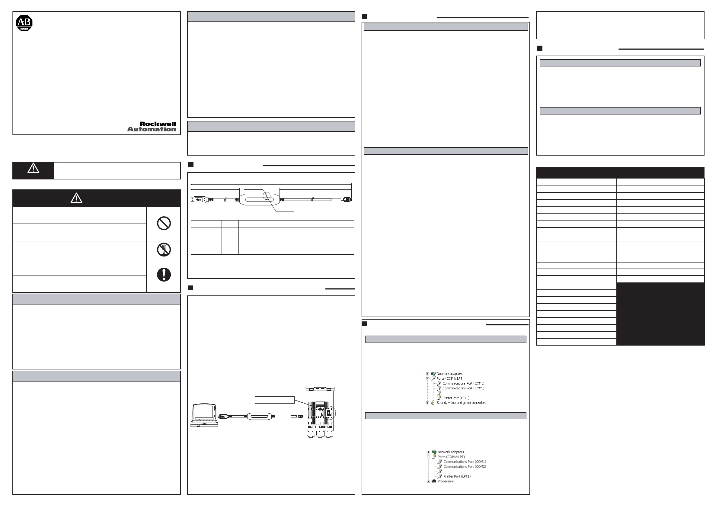
Cable Configuration to PC and Controller
Use the following procedure to connect the Temperature Controller to the personal
computer using the 900-CPOEM1 USB Cable. The cable is used for communications
with the COM port of the personal computer.
To perform communications using the 900-CPOEM1, set the communications port
(COM port) number used by the software to the communications port (COM port)
number that has been assigned to the 900-CPOEM1 USB Cable.
1. First, turn ON the power to the Temperature Controller and DC.
Note: If power is not turned on to the PC and Temperature Controller first before
connecting the cable, damage may result to the Temperature Controller
communication port.
2. Connect the USB Cable
Connect one end of the cable to the personal computer's USB port and the other
end to the Setting Tool port on the Temperature Controller.
Connecting to the Temperature Controller
·
Personal computer
USB port
Note: Hold the connector ends securely when connecting
or disconnecting the cable.
3. Install the Driver
Install the driver to enable using the 900-CPOEM1 USB Cable with the personal
computer. Refer to using Windows 2000 and using Windows XP, next column to
right.
Installation
·
After the driver is installed, when the cable is connected to the personal computer,
the operating system will detect the 900-CPOEM1 as a new device. Install the
driver. Refer to Installing the Driver.
900-CPOEM1 port
Temperature Controller
Bottom View of
900-TC16 Controller*
*Port for 900-TC8 is on the bottom
but on the opposite side
Installing the Driver
Using Windows 2000
To use the 900-CPOEM1 cable you must first download the USB Driver from the 900
1)
Temperature website located at:
www.ab.com/industrialcontrols/products/relays_timers_and_temp_controllers/single
_loop_temp-heater_controllers/900tc.html.
Go to "Get Software" (upper right of screen), click on 900-CDOEM1 Driver and follow the
2)
instruction for downloading the driver to your PC.
Insert the 900-CPOEM1 USB Cable into the USB port of the personal computer.
3)
The Found New Hardware Wizard will start. Click the Next Button.
Select Search for a suitable driver for my device (recommended) and click the Next
4)
Button.
When the driver file is found, click the Next Button.
5)
The Completing Found New Hardware Wizard Dialog Box will be displayed. Click the
6)
Finish Button.
The Found New Hardware Wizard will be displayed again. Click the Next Button.
7)
Select Search for a suitable driver for my device (recommended) and click the Next
Button.
When the driver file is found, click the Next Button.
8)
The Completing Found New Hardware Wizard Dialog Box will be displayed. Click the
Finish Button to complete installation.
After installation is completed, the COM port number will be automatically assigned. For
9)
details on checking the assigned COM port number, refer to 4. Confirming Automatically
Assigned COM Port Numbers.
Using Windows XP
To use the 900-CPOEM1 cable you must first download the USB Driver from the 900
1)
Temperature website located at:
www.ab.com/industrialcontrols/products/relays_timers_and_temp_controllers/single
_loop_temp-heater_controllers/900tc.html.
Go to "Get Software" (upper right of screen), click on 900-CPOEM1 Driver and follow the
2)
instruction for downloading the driver to your PC.
The Found New Hardware Wizard will start. Select Install the software automatically
3)
(Recommended) and click the Next Button.
A message will be displayed stating that the software you are installing for this hardware
has not passed Windows Logo testing to verify its compatibility with Windows XP. Click the
4)
Continue Anyway Button.
5)
The Completing Found New Hardware Wizard Dialog Box will be displayed. Click the Fin-
6)
ish Button.
The Found New Hardware Wizard will star t again. Select Install the software automati-
7)
cally (Recommended) and click the Next Button.
A message will be displayed stating that the software you are installing for this hardware
8)
has not passed Windows Logo testing to verify its compatibility with Windows XP. Click the
Continue Anyway Button.
The Completing Found New Hardware Wizard Dialog Box will be displayed. Click the Fin-
9)
ish Button to complete installation.
After installation is completed, the COM port number will be automatically assigned. For
details on checking the assigned COM port number, refer to 4. Confirming Assigned COM
Port Numbers.
This product is compatible with Windows XP and Allen-Bradley's operation inspec-
Note1 :
tion has verified normal operation. If driver installation is cancelled before it has
been completed, the driver will not be completely installed, which will result in abnormal communications. If this occurs, uninstall the driver and then reinstall the driver correctly.
Allen-Bradley recommends installing the driver separately for each USB port when
Note2 :
using the 900-CPOEM1 for the first time. The 900-CPOEM1 will be assigned a COM
port number for each USB port of the personal computer. The same COM port number can be used even if a different cable is connected to the USB port.
Confirming Automatically Assigned
COM Port Numbers
Using Windows 2000
1)
Select My Computer - Control Panel and then double-click the System Icon to
display the System Properties Window. Click the Hardware Tab and then click
the Device Manager Button. Select Devices by Type from the View Menu.
For example, if Allen-Bradley 900-CPOEM1 USB Serial Port (COM4) is displayed under the Ports (COM & LPT) heading in the directory tree, the device is
assigned to COM port 4.
(Example)
2)
Exit the Device Manager.
1)
Select My Computer - View System Information to display the System
Properties Window. Click the Hardware Tab and then click the Device Manager
Button. Select Devices by Type from the View Menu.
For example, if Allen-Bradley 900-CPOEM1 USB Serial Port (COM3) is
displayed under the Ports (COM & LPT) heading in the directory tree, the device
is assigned to COM port 3.
(Example)
2)
Exit the Device Manager.
Allen-Bradley 900-CPOEM1 USB Serial Port (COM4)
Using Windows XP
Allen-Bradley 900-CPOEM1 USB Serial Port (COM4)
Note: In the software communications settings, select the COM port number
that was confirmed in the device manager and then start communications.
Uninstalling the Driver
Using Windows 2000
1)
Select Start - Control Panel and double-click the Add/Remove Programs Icon.
2)
The Add/Remove Programs Window will be displayed.
Select Allen-Bradley 900-CPOEM1 Drivers and click the Change/Remove Button.
3)
Click the Continue Button to start uninstallation.
4)
Click the Finish Button to complete uninstallation.
Using Windows XP
1)
Select Start - Control Panel and double-click the Add or Remove Programs Icon.
2)
The Add or Remove Programs Window will be displayed.
Select Allen-Bradley 900-CPOEM1 Drivers and click the Change/Remove Button.
3)
Click the Continue Button to start uninstallation.
4)
Click the Finish Button to complete uninstallation.
Table A
900-TC8 Controllers 900-TC16 Controllers
900-TC8RGTH1Z25
900-TC8RGTZ25 900-TC16YGTZ25
900-TC8RVGTZ25
900-TC8RGTH3Z25 900-TC16ACGTZ25
900-TC8VGTH1Z25
900-TC8VGTZ25 900-TC16VGTU25
900-TC8VYGTZ25 900-TC16ACGTU25
900-TC8VVGTZ25
900-TC8VGTH3Z25 900-TC16YABZ25
900-TC8ACGTZ25 900-TC16VABZ25
900-TC8ACYGTZ25 900-TC16ACABZ25
900-TC8ACVGTZ25 900-TC16RABU25
900-TC8RGTH1U25 900-TC16VABU25
900-TC8RGTU25 900-TC16ACABU25
900-TC8VGTH1U25
900-TC8VGTU25
900-TC8ACGTU25
900-TC8RABH1Z25
900-TC8RABZ25
900-TC8VABH1Z25
900-TC8VABZ25
900-TC8VYABZ25
900-TC8ACABZ25
900-TC16RGTZ25
900-TC16VGTZ25
900-TC16RGTU25
900-TC16RABZ25
 Loading...