

Page 1
Installation Instructions
R
PHOTOSWITCH
Sensors 10- 55V DC/20- 40V AC Models 70- 264V AC/DC Models
2m 300V cable 60--2728 60--2730
Models
5-pin mini QD 60--2729 60--2731
Sensing Mode Retroreflective
Sensing Distance
Transmitting LED Visible Red, 660nm
Field of View
Optical
Operating Mode Light/dark operate selectable
Sensitivity Adjustment Yes
Operating Voltage 10--55V DC/20--40V AC 70--264V AC/DC
Supply Current 40mA max 15mA max
Power Consumption 2.2W / 1.6VA
Protection False pulse on power-up, overvoltage, reverse polarity, outputs short circuit (SCP) protected
Output Type SPDT EM Relay
Electrical
Output Load Current/Voltage 1A @ 264V AC, 2A @ 132V AC
Response Time 15ms
Leakage Current Not applicable
Housing/Lens Material
LED Indicators See table below
Connection Types SJTOW outdoor rated 2m, 300V cable, 5-pin AC mini QD
Supplied Accessories AB #60--2725 impact bracket
Mechanical
Optional Accessories #92--39 reflector, 889N--F5AF--6F cordset
Operating Temperature
Relative Humidity 5–95%
Operating Environment NEMA 3, 4, 4X, 6P, 13, IP67 (IEC529); 1200psi (8270kPa) washdown
Approvals c--UL recognized (UL325), CE marked for all applicable directives
Protections All versions: false pulse, reverse polarity, overload, short-circuit
Environmental
Vibration 10--55 Hz, 1mm amplitude, meets or exceeds IEC 60947- -5--2
Shock 30G with 1ms pulse duration, meets or exceeds IEC 60947--5--2
UL325 Recognized Photoelectric Sensors
2.54cm to 9.15m (1I to 30i) with AB#92--39 reflector
1.5_
Valox t/Acrylic
-- 3 4 _Cto+70_C(--29_Fto+158_F)
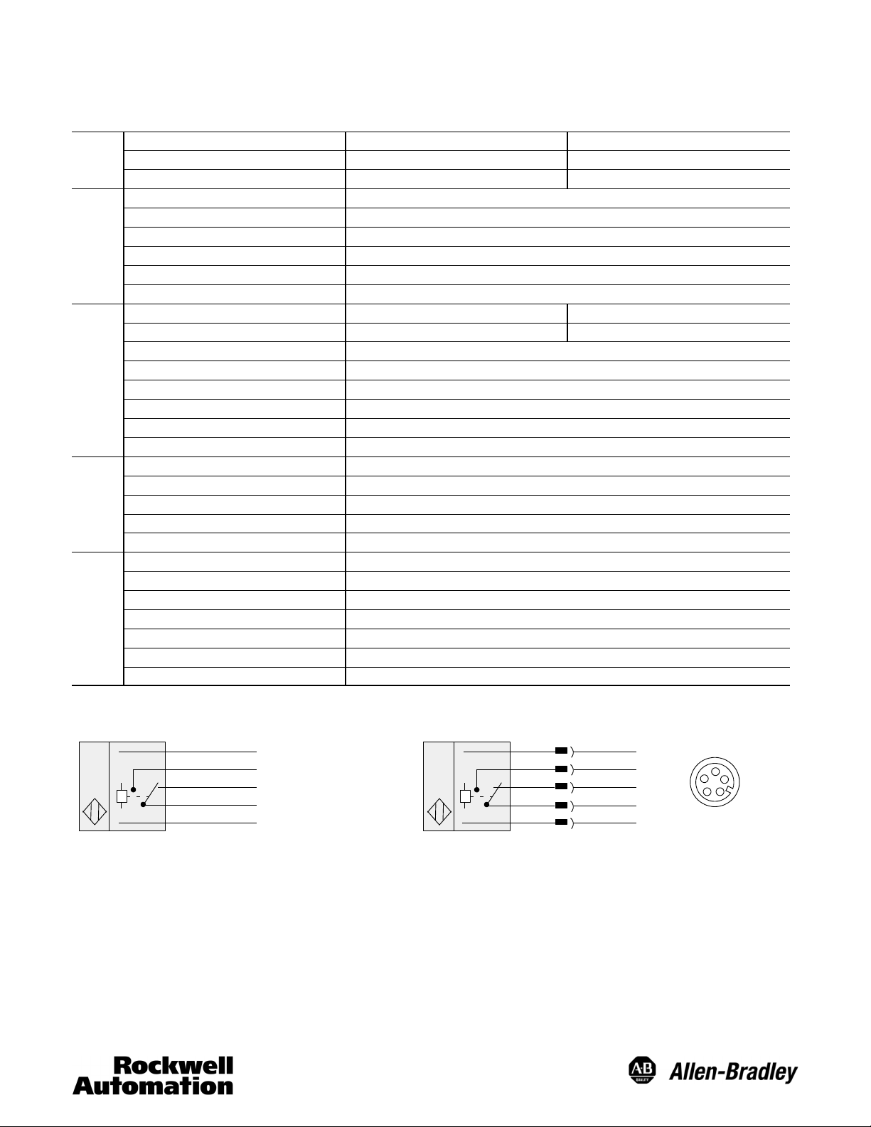
Wiring Diagrams
Brown
Black (NO)
White (NC)
Orange (C)
Blue
Note: Quick-disconnect wiring codes shown are valid for Allen-Bradley cables only.
(+)L1
(--) L2
5-pin AC/DC Mini QD Model: 60-- 2729, 60--2731Cable Model: 60--2728, 60--2730
4Brown
1Black(NO)
5 White (NC)
3Orange(C)
2Blue
(+)L1
(--) L2
2
3
1
4
5
Page 2
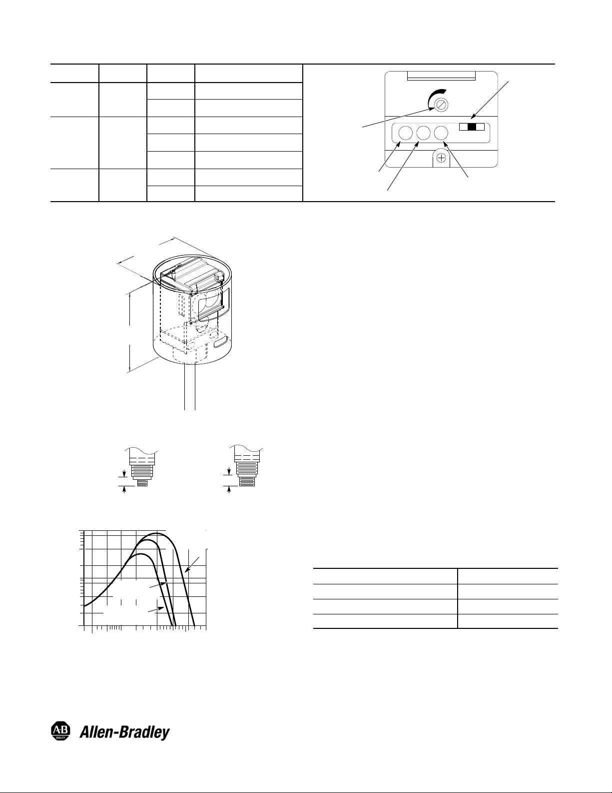
User Interface
)
V
Label Color State Status
Output Green
OFF Sensor output de-activated
ON Sensor output activated
T op View Detail
Light/Dark
Operate Switch
OFF Margin < 2.5
Margin/SCP Red
Power Yello w
ON Margin >2.5
Flashing Output SCP active
OFF Sensor not powered
ON Sensor powered
Dimensions—mm (inches)
63.5
(2.5)
75
(2.9)
Connector Version
Micro Style Mini Style
13.97 (0.550)
Typical Response Curves
100
80
40
20
10
8
4
Operating Margin
2
1
51mm
(2I)
32mm (1.25I)
Reflector
16mm (0.625I)
Reflector
0.3m
0.6m
(1i)
(2i)
1.5m
(5i)
17.78 (0.700)
76mm (3I)
Reflector
3m
(10i)
15m
(50i)
Sensitivity Adjustment
Red Margin/
SCP Indicator
Green Output
Energized Indicator
Yellow Power On
Indicator
Installation
The sensor must be mounted on a firm, stable surface or
support. A mounting platform which is subject to excessive
vibration or shifting may cause intermittent operation. All
wiring between the sensor and the automation system should
conform to the National Electric Code and all applicable local
codes. See wiring diagrams for proper connections.
When power is applied to the sensor, the yellow indicator will
turn ON. Visually sight the sensor at the reflector until the
green indicator turns ON (with sensor in light operate mode)
or OFF (with sensor in dark operate mode). Continue to align
the sensor vertically and horizontally until the red indicator
turns ON.
Once the sensor has been properly aligned, the sensitivity can
now be set. This is accomplished through the use of the
sensitivity knob on the user interface panel. Open the top
cover to access this knob. The default setting is in the full
clockwise position which will provide maximum sensitivity and
range. Turn the knob counterclockwise until the red indicator
turns OFF. This indicates that the threshold where the sensor
is receiving at least 2.5X the required amount of light (margin)
necessary to activate the output. Turn the knob clockwise to a
point where the indicator just turns ON. Normal industrial
environments range from moderately dusty to extremely dirty.
A higher operating margin is typically desirable to overcome
the accumulation of dust/dirt on the optics lens over a period
of time. Refer to the Typical Response Curve to determine the
margin versus distance characteristics of the sensor. Close
the top cover securely.
QD Cordsets and Accessories
Description Catalog Number
1.8m (6ft) 5-pin, Mini QD Cordset 889N- F5AF- 6F
76mm(3in)DiameterwithCenterMountHole 92- 39
32mm (1.25in) Diameter 92- 47
Operating Distance
isit our web site at:
http://www.ab.com/sensors
2
Publication 75002--296--01(B
November 2000
PrintedinUSA
 Loading...