

Page 1
22 Approvals (Hazardous Location)
Agency Standard
CSA
No. 157
CSA--C22.2
No. 213
CSA--C22.2
No. 142
Ex ia Intrinsically Safe for Class I; Division 1; Groups A, B, C, and D; Class III, Division 1,
Vmax=31.5V,Imax=150mA, Ci=0F and Li=0mH, T3A, Type 4X.
Nonincendive for Class I; Division 2; Groups A, B, C, D; T3A, Type 4X
FM
3610, 3611
3810, 3600 Nonincendive for Class I; Division 2; Groups A, B, C, D; T4, Type 4X
CSA--C22.2
Intrinsically Safe for
Class I; Division 1; Groups A, B, C, and D Hazardous (Classified) Locations.
Vmax=31.5V,Imax=150mA, Pmax=0.95W,Ci=0uF,Li=0mH, T4, Type 4X
-- 3 4 _Cto+70_C(--29_F to +158_F)
11 Max Leakage Current — 10A
7 Supply Voltage 14--30VDC 13--30VDC
8 Max Current Consumption 16mA 25mA
9 Output — NPN and PNP
5 Transmitting LED Infrared 880mn —
6 Indicators Yellow: Power
2 Sensing Distance 106m (350ft)
3 Field of View
4 Sensitivity Adjustment Yes
4-pin DC Mini QD 42GRL--9540--QD1 42GRR--9500--QD1
1
Catalog Number
2m Cable 42GRL--9540 42GRR--9500
4-pin DC Micro QD 42GRL--9540--QD 42GRR--9500--QD
Sensors
Source Receiver
Transmitted Beam
1.5_
Yellow: Power, Green: Output, and
Red: Margin
10 Max Load Current — 15mA (NPN) 8.5mA (PNP)
installation Instructions—Series 9000 PHOTOSWITCH
12 Response Time 10ms (ON) 5ms (OFF)
13 Volta ge Drop 4.5V (NPN) 6.0V (PNP) @ Max Load Current
14 Operating Temperature
15 Relative Humidity 5% to 95%
16 Housing/Lens Material Acrylic
17 Environmental Protection NEMA3, 4, 4X, 6P, 13, IP67 (IEC 529); 1200psi (8270kPa) Washdown
18 Vibration 10--55Hz, 1mm amplitude, Meets or exceeds IEC 60947--5--2
19 Shock 30G with 1ms pulse duration, Meets or exceeds IEC 60947--5--2
20 Electrical Protection False Pulse, Reverse Polarity, Overload, Short Circuit
21 Approvals (Ordinary Locations) UL Listed, CSA Certified, CE Marked for all applicable directives
(2.190)
55.62
Cable Version
4000
10000
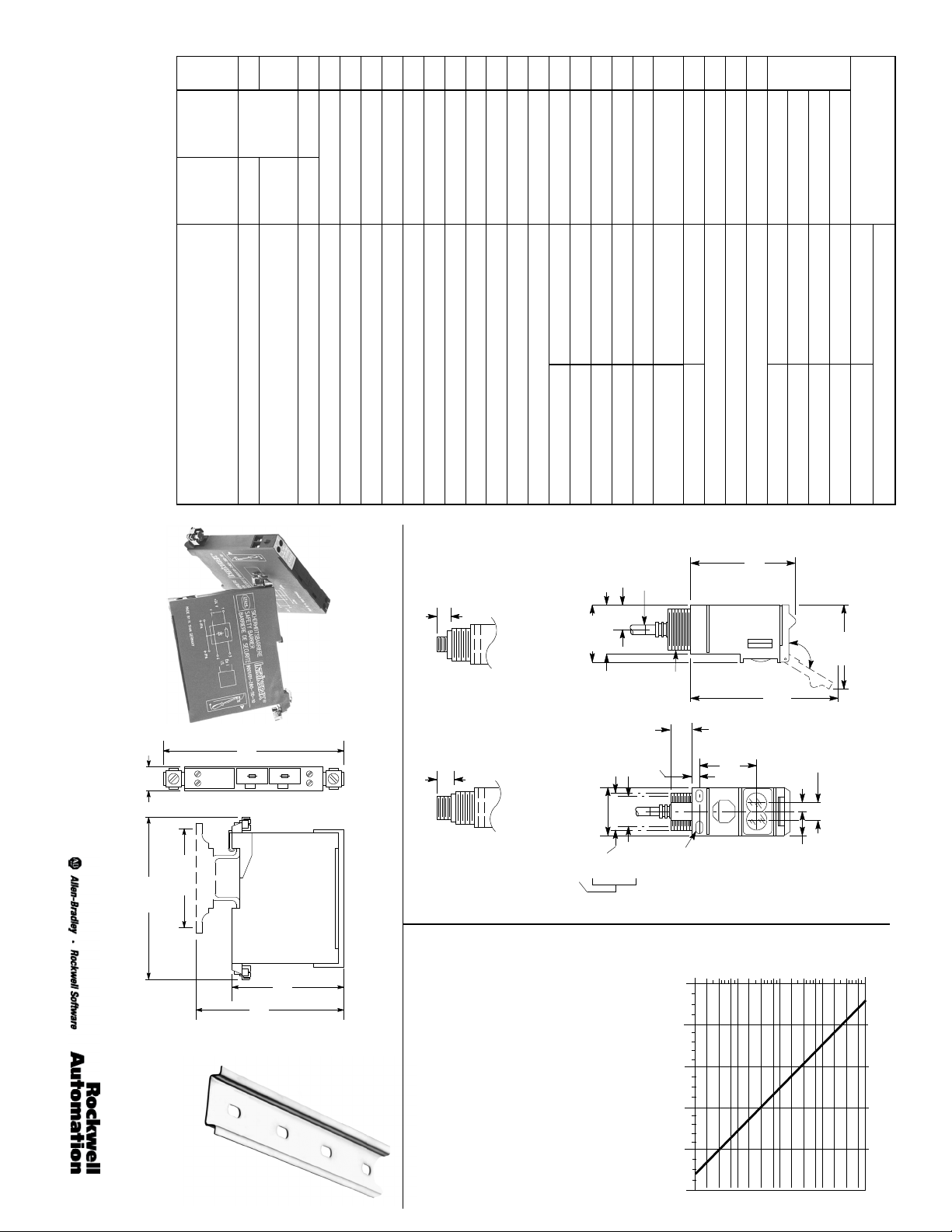
Dimensions—mm (inches)
R
Intrinsically Safe Photoelectric Sensors
T ypical Response Curve
Connector Version
Allen-Bradley Series 897H
Zener Diode Barrier
1
122
102
(4)
160mA
(0.5)
160mA
(2.1875)
56
34
Intrinsic
Barrier
Safety
12.5
102
(4)
160mA
160mA
12
(2.75)
70
(3.75)
93.5
13.97 (0.550)
Micro Style Mini Style
17.78 (0.700)
32.66 (1.286)
(1.575)
40.00
(1.650)
41.91
Mounting Hole
Centerline
(1.195)
30.35
6.5 (0.255/0.245) Dia.
16.76 (0.660)
(0.970)
24.69
(0.215)
Cable Length
2m (6.5 )
External Thread
Internal Thread
1/2 NPSM
M30 X 1.5
(0.625)
15.87
5.46
5.21 (0.205) X
Slot, 2 PLCS
8.13 (0.320)
1
0.3m
(1)
1.8m
(5)
(1.670)
4
(2.950) Ref
74.93
42.41
Operating Margin
10
40
Max. Travel
(4.080)
103.63
15.24 (0.600)
7.62 (0.300)
(0.825)
20.96
1000
100
400
Operating Distance
(10)
DIN Rail Mounting Kit
0.3m (1ft)
#64--136
3m
(50)
15m
(100)
30m
(500)
150m
Page 2
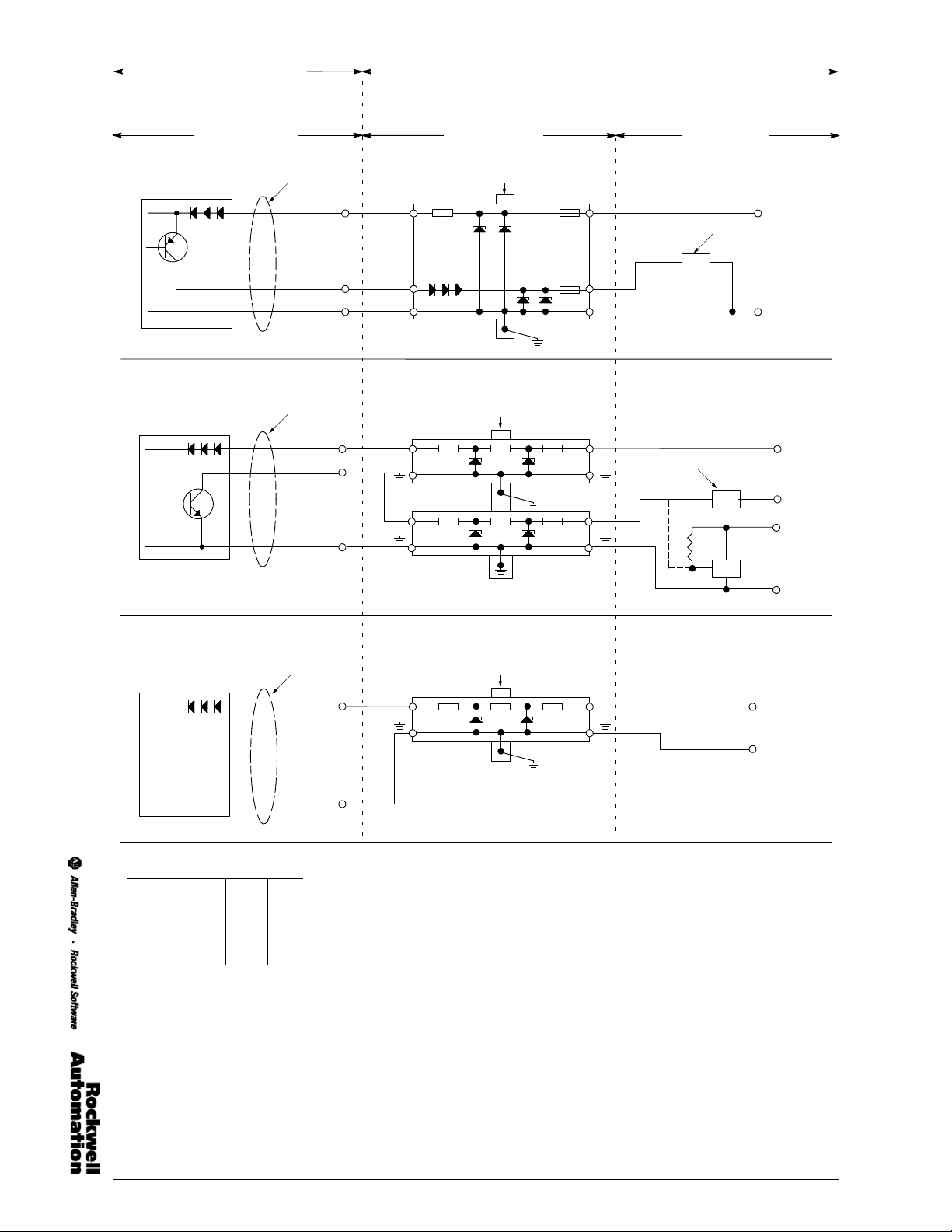
Hazardous (Classified) Location
(See Note 1)
Hazardous (Classified) or Nonhazardous Loca-
tion
(See Note 2)
Receiver Model Numbers:
42GRR--9500, 42GRR--9500--QD, 42GRR--9500--QD1
Cable
Brown
Black
Blue
Receiver PNP Output Wiring
Photoelectric Sensors
Receiver Model Numbers:
42GRR--9500, 42GRR--9500--QD, 42GRR--9500--QD1
Cable
Brown
White
Blue
Receiver NPN Output Wiring
Light Source Model Numbers:
42GRL--9540, 42GRL--9540--QD, 42GRL--9540--QD1
(Pin 1)
(Pin 4)
(Pin 3)
(Pin 1)
(Pin 2)
(Pin 3)
A--B #897H--S214
3
4
A--B #897H--S150
3
A--B #897H--S150
3
Zener Diode Barriers
Barrier Bus
Barrier Bus
(less than 1Ohm)
Earth Ground
(less than 1Ohm)
Earth Ground
1
Power Supply
2
Supply Return
1
Power Supply
Sourcing PLC Input
1
Supply and Signal Return
Power Supply &
Load Circuits
Sinking PLC Input
8.5mA Max.
15mA
Max.
24V DC Nom.
Signal
Return
Load
Supply
TTL
Device
(+)
(--)
24V DC Nom.
(+)
24V DC Nom.
(+)
5V DC Nom.
(+)
(--)
Cable
Light Source Wiring
Table 1: Entity Parameters
Sensor Barrier
Vmax 31.5V ≥ Vt
Imax 150mA ≥ It
Pmax 0.95W ≥ Pt
Ci 0F ≤ Ca
Li 0mH ≤ La
Rockwell Automation/Allen-Bradley
Control Drawing #75002--200--01(Ver 03)
Blue
Brown
Barrier Bus
1
Power Supply
(Pin 1)
A--B #897H--S120
3
Supply Return
Earth Ground
(Pin 3)
Notes:
1. Class I; Division 1, Group A, B, C, D. Class I; Division 2, Group A, B, C, D.
2. Class I; Division 2, Group A, B, C, D if equipment and installation is per national standards.
3. Division 2 applications without the use of a barrier must be installed in accordance with the NEC and CEC.
4. Safety barriers are not required for Class I, Division 2 Group A, B, C, D non-incendive installations when installed per the CEC.
5. Entity parameters of Safety Barriers must match Table 1. Cable values for capacitance and inductance must be added to Ci and Li
values.
6. In Division 2 installations without barriers, observe the following warning: Warning explosion hazard. Do not disconnect equip-
ment unless power has been switched off or the area is known to be nonhazardous.
7. Wiring between the sensor and safety barriers should comply with all relevant national standards and/or those standards set forth by
the authority having jurisdiction at the installation site. These may include Article 504 of the NEC, ANSI/ISA RP--12.6 (United States),
or CSA C22.2 (Canada).
8. Intrinsically Safe wiring must be separated from nonintrinsically safe wiring by at least 50mm (2in). The use of tiedowns, grounded
metal partitions, or approved insulating partitions are acceptable.
9. Intrinsically safe wiring shall be identified as such with labels placed no more than 7.62m (25ft) apart. The color light blue is internationally recognized as identifying intrinsically safe wiring.
10. The use of a gas-tight seal is required at the point where the wiring transitions the hazardous and nonhazardous location.
11. Intrinsically safe associated apparatus, cable shields, enclosures, and raceways (metal) shall be grounded in accordance with the
requirements of Section 250 of the NEC.
12. Nonhazardous location equipment must not contain a source voltage of greater than 250V unless sufficient means have been
employed to prevent the shorting of a source voltage greater than 250V onto the nonintrinsically safe terminals of the associated
apparatus.
13. Nonhazardous location equipment must not contain a source voltage of greater than 250V.
14. As all wiring contains stored energy (capacitance and inductance), all conductors must be considered when determining the length of
intrinsically safe circuits. When available the actual values should be used. If not available, values of 60pF/foot for capacitance per
wire pair and 0.2uH/foot for inductance are accepted and may be used.
15. Maximum operating ambient temperature range: --34_Cto+70_CType4X.
16. Changes to this document are not permitted without prior approval by the testing agency.
17. WARNING:Potential electrostatic discharge hazard. Do not rub with dry cloth.
(less than 1Ohm)
24V DC Nom.
(+)
(--)
Page 3

12.7
T orx Replacement Screw Kit #129--135 and
22 Approvals(Hazardous Location)
11 Max Leakage Current Courant de Fuite maximale Corrente Massima di Dispersione Max. Leck- Strom Corriente Máxima de Fuga Máx. Corrente de Fuga
7 SupplyVoltage Tension d’alimentation Tensione di Alimentazione Versorgungsspannung Voltajede Alimentación Tensãode Alimentação
8 MaxCurrent Consumption Consommation maximale Assorbimento Max. Stromaufnahme Máximo Consumo de Corriente Consumo de Corrente Máxima
9 Output Sortie Uscita Ausgang Salida Saída
6 Indicators Voyants (ou) Indicateurs Indicatori Anzeigen Indicadores Indicadores
5 Transmitting (LED) LED d’émission LED di Trasmissione Lichtquelle (LED) LED de Transmisión LED de Transmissão
3 Field of View Champ de vision Campo di Visione Öffnungswinkel CampodeVisión CampodeVisão
4 SensitivityAdjustment Réglagede Sensibilité Regolazione della Sensibilità Empfindlichkeits-Einstellung Ajuste de Sensibilidad Sensibilidade
2 SensingDistance Distancede Détection Distanza di Rilevamento Reich--/Tastweite Dispositivo Sensor Alcance
1
Catalog Number Référence de Commande Numero di Catalogo Bestellnummer Número de Catálogo Código de Catálogo
2m Cable Câble 2m 2m Cavo 2m Kabel 2m Cable Cabo 2m
4-pin DC Micro QD Connecteur micro M12 4-broches Connettore Micro M12 per CC a 4 pin 4-poliger M12--Mikro-Stecker DC Conector micro 4 pines CC Conector Padrão M12
4-pin DC M ini QD Connecteur mini 4-broches c.c.
Screwdriver with torx head to be used with torx replacement screw kit 129--135.
10 MaxLoad Current Courant de Charge maximale Corrente Massima di Carico Max. Laststrom Corriente de Carga Máx.Corrente de Carga
12 ResponseTime Temps de Réponse Tempo di Risposta Ansprechzeit Tiempo de Respuesta Tempode Resposta
13 Voltage Drop Chute de tension Caduta di Tensione Spannungsabfall CaidadeTensión Queda de Tensão
14 OperatingTemperature Température de Fonctionnement Temperatura di Funzionamento Betriebstemperatur Temperaturade Operación Temperaturade Operação
15 RelativeHumidity HumiditéR elative Umidità Relativa Relative Luftfeuchtigkeit Humedad Relativa Umidade Relativa
16 Housing/LensMaterial
17 EnvironmentalProtection Protection de l’environnement Gradodi protezione Schutzart Protección Ambiental Proteção Ambiental
18 Vibration Vibration Vibrazione Vibration Vibración Vibração
19 Shock Choc Urto Schock Impacto Choque
20 ElectricalProtection Protection électrique Protezioni Elektrischer Schutzeinrichtungen Protección Eléctrica Proteção Elétrica
21 Approvals(Ordinary Locations)
T orx Screwdriver #57--144
(0.5)
Accessories—mm (inches)
Swivel/Tilt Mounting Assembly #60--2439
English Français Italiano Deutsch Español Português
Matériaux du Boîtier/du Couvercle/
Homologations (emplacement or-
dinaire)
Homologations (emplacement à
risque)
Approvazioni Approbation (normale Umgebung) Aprobaciones Aprovações
Approvazioni Approbation (exlposionsgefährdete Umgebungen) Aprobaciones Aprovações (Locais que apresentam risco)
des Lentilles
Copertura/delle Lenti
20.32
(0.8)
27.94
(1.1)
50.8
(2.0)
Materiale dell’Involucro/per la
Connettore Mini 7/8I per CC a 4 pin
66.04
(2.6)
28.6
(1.125)
29.21
(1.15)
Gehäusematerial/Werkstoff der
Abdeckung/Linsenmaterial
Material del Alojamiento/de la Cubierta/del
3
Lente
Material da Caixa/Tampa/Lente
4-poliger Mini-Stecker DC Conector mini 4 pines CC Mini DR CC 4 Pinos
30.5 (1.20)
Dia.
50.8
(2.00)
7.1
(0.28)
3.0 (0.119)
Ref
31.8
(1.25)
48.3
(1.90)
2PL
60.2
(2.37)
90
_
7.1
(0.28)
50.8 (2.00) Dia.
30.5 (1.200) Dia.
19 (0.75)
2PL
90
_
45_
31.8
(1.25)
67.3
(2.65)
Universal Mounting Assembly #60 --2421
71.1
(2.80)
360_ Rotation Mounting Assembly #60--2513
90_
Through Hole
Mounting
Optional Mounting
Assembly #60- -2513
119. 4
(4.70)
77.5
(3.05)
67.3
19.0
(0.75)
(2.65)
55.8
50.8
(2.00)
30.5 (1.200)
36.3
7.1
M5x0.8x53mm
Combination
Screws and Nuts
(Supplied)
Hardware Kit
(Supplied)
#129--130
(0.28)
(1.43)
Dia.
(2.20)
71.1
(2.80)
31.8
(1.25)
7.6
(0.30)
Page 4

Transmitted Beam Source Émetteur Emettitore Einweglichtschranke, Sender Fuentesde rayos transmitidos Feixe Transmitido, Emissor
A
R
Transmitted Beam Receiver Récepteur Ricevitore Einweglichtschranke, Empfänger Receptor de rayos transmitidos Feixe Transmitido, Receptor
Infrared Infrarouge Infrarosso Infrarot Infrarrojo Infravermelho
Indicators
Yellow: Power
Green: Output
Red: Margin
Acrylic Acrylique Acrilico Acryl Acrílico Acrílico
False Pulse, Reverse Polarity, Overload, Short Circuit
10--55Hz,1mm amplitude, meets or exceeds IEC
60947--5 --2
30G with 1ms pulse duration 30 G pendant 1 ms IEC 60947--5 --2 30G con durata impulso 1ms 30G bei 1ms Pulsdauer 30G con una duración de pulso de 1 ms 30G com duração de pulso de 1ms
FM Approved, CSA Certified FM approuvé ,CSA et marquage FM approvato, CSA e marcati FM genehmigt, CSA-Zertifikat FM aprobado, Certificado CSA FM aprovado, Certificado por CSA
Agency, Standard Agence, Standards Omologazioni Agentur, Standard Agencia,Estándar Padrão da agência
Typical Response Curve
Infrared Fiber Optic Transmitted Beam Barrage en fibre optique, infra rouge Barriera a fibre ottiche per infrarossi Lichtleiter (infrarot Lichtquelle), Durchlicht--Ausführung Barrera Infrarroja de Fibra Optica Feixe Transmitido de Fibra Ótica Infravermelho
Operating Margin Marge de fonctionnement Margine operativo Funktionsreserve Margen Operativo Margem
Operating Distance Distance de fonctionnement Distanza di funzionamento Arbeits--Reich--/Tastweite Distancia de Operación Alcance
Accessories Accessoires Accessori Zubehör Accesorios Acessórios
Torx Replacement Screw Kit Kit de vis Torx de remplacement Kit sostituzione viti torx Torxschraubensatz Kit de Tornillos de Repuesto Torx Conjunto de Parafusos Estrela de Reposição
Screwdriver with torx head to be used with torx
replacement screw kit 129--135.
Swivel/Tilt Mounting Assembly Ensemble de montage à rotule Supporto di montaggio orientabile Kugelgelenkhalterung Escuadra de Montaje Oscilante/Basculante Suporte para Montagem Tipo Rótula
Universal Mounting Assembly Ensemble de montage droit Supporto di montaggio assiale Gerade Montagehalterung Brazo de Montaje Recto Suporte para Montagem Tipo Plano
360_ Rotation Mounting Assembly
All Versions Except Fiber Optic Toutes les versions sauf fibre optique Tutte le versioni eccetto fibre ottiche Alle Versionen ausser Lichtleiter-Verstärker Todos los Versiones Excepto los de Fibra Optica Todas as Versões, Exceto Fibra Optica
Cable Version, Connector Version Version de câble, Versionde connecteur Versione Cavo, Versione Connettore Kabel--, Steckverbinder--Ausführung Versión de Cable, Versión de Conector Versão Pré-Cabeada, Versão com Conector
6. As all wiring contains stored energy all conductors
source voltage of greater than 250V.
must be considered when determining the length of
intrinsically safe circuits. When available the actual
values should b e used. If not available, values of
60pF/foot for capacitance per wire pair and
0.2uH/foot for inductance may be used.
where the wiring transitions the hazardous and
nonhazardous location.
enclosures, and raceways (metal) shall be grounded
in accordance with the requirements of Section 250
of the NEC (United States).
3. The use of a gas-tight seal is required at the point
4. Intrinsically safe associated apparatus, cable shields,
5. Nonhazardous location equipment must not contain a
2. Intrinsically safe wiring shall be identified as such
nonintrinsically safe wiri ng by at least 50mm (2in).
The use of tiedowns, grounded metal partitions, or
approved insulating partitions are acceptable.
with labels placed no more than 7.62m (25ft) apart.
The color light blue is internationally recognized as
identifying intrinsically safe wiring. It is recommended
that cables, terminal blocks, raceways, cable ducts,
and junction boxes be light blue in color.
Wiring between the sensor and the safety barriers
The 42GRx--95xx is approved as an intrinsically safe
Selection and Installation
apparatus under the entity concept by CSA for
installation into a Class I; Division 1; Groups A,B,C,D
hazardous location when wired as shown in the attached
control drawing (75002--200). The sensor must be
connected to an approved safety barrier(s) for installation
into Division 1 locations.
should comply with all relevant national standards and/or
those standards set by the authority having jurisdiction at
the installation site. These may include Article 504 of the
National Electrical Code, ANSI/ISA RP--12.6 (United
States), or CSA --C22.2 (Canada). Listed below are
minimum requirements for installation.
1. Intrinsically Safe wiring must be separated from
English Français Italiano Deutsch Español Portuguêas
Sélection et Installation
sécurité intrinsèque sous le concept d’entité par CSA pour
une installation dans une classe I ; Division 1 ; Groupes A, B,
C, D emplacement à risque (une fois câblé comme montré
sur le schéma de commande (75002.200) ci--joint. Le capteur
doit être relié à une barrière de sécurité approuvée pour une
installation dans des emplacements de Division 1.
devrait être conforme à toutes les normes nationales stan-
dards appropriées et/ou à celles fixées par l’autorité ayant la
juridiction du site d’installation. Celles -ci peuvent inclure
l’article 504 du Code de l’cAnsi/isa RP--12.6 (Etats--Unis),ou
du Code National Electrique CSA--C222.2 (Canada). les
conditions minimum pour l’installation sont énumérées ci--
dessous.
1. Le câblage de sécurité intrinsèque doit être séparé du
3. L’utilisation d’un joint étanche au gaz est exigée sur les
Tournevisà tête Torx utilisable avec le kit de vis de
Ensemble de montage à rotule Supporto di montaggio orientabile Kugelgelenkhalterung Escuadra de Montaje Oscilante/Basculante Suportepara Montagem Tipo Rótula
PHOTOSWITCH
Valox
R
is a registered trademark of General Electric Company.
remplacement 129--135.
Cacciavite con testa forx da usare col kit di sostituzione viti
129--135.
Courbe typede réponse
Curva di risposta Diagramm. Relative Empfangs Lichtstärke /
Amplitude 1 mm, 10--55Hz IEC 60937--5--2
Indicatori
Giallo: alimentazione
Verde: uscita
Rosso: margine
Falsi Impulsi, Inversione di Polarità, Sovraccarichi,
CortoCircuito
10--55Hz,1mm di ampiezza, soddisfa o supera le IEC
947--5--2
pour la capacité d’une paire de fils et de 0.2uH/foot pour
inductance peuvent être utilisées.
les conducteurs doivent être conçus en fonction de la
longueur des circuits de sécurité intrinsèque. Si elle est
disponible, les valeurs actuelles doivent être utilisées.
Dans le cas contraire, des valeurs de 60picoFarad/foot
dovrebbero utilizzare I valori attuali. Se non disponibili si
devono usare i valori di 60pF/piedi di capacità per coppia
e 0.2uH/piedi di induttanza.
Indicateurs
Jaune : a limentation
Vert:sortie
Rouge : m arge
Fausses impulsions, Inversion de polarité, surcharges, courts
circuits
4. Les appareils associés à la sécurité intrinsèque, boucliers
5. Le matériel installé sur un emplacement sans risque ne
6. Tout le câblage contenant une énergie accumulée, tous
être établis en accord avec les exigences de la Section
250 du NEC (Etats--Unis).
doit pas contenir de source de tension de plus de 250 V.
6. Poichè il collegamento elettrico contiene energia
contenere una fonte di tensione maggiore di 250V.
immagazzinata lo si deve considerare nel determinare la
lunghezza dei circuiti interni di sicurezza. Se disponibili si
5. Gli accessori della zona non a rischio non devono
de câble, pièces jointes et chemins de câbles devront
sezione 250 del NEC (Stati Uniti).
dovrebbero essere messi a terra secndo le norme della
bleue claire.
points de transition de câblage sur tous les emplace-
ments qu’ils soient à risque ou non.
3. La guarnizione di tenuta ai gas é necessaria nei passaggi
4. Gli apparecchi associati alla sicurezza intrinseca (cavi
elettrici tra le zone pericolose e non.
schermati, le chiusure le canalizzazioni di metallo)
2. Le câblage de sécurité intrinsèque devra être identifié en
câblage de sécurité non intrinsèque par 50mm (2in) au
moins. L’utilisation des cloisons reconnues comme étant
isolantes sont acceptables.
tant que tel avec des étiquettesplacées, à part, à 7.62m
(25ft) maximum. La couleur bleue claire est internation-
alement reconnue comme moyen d’identifier un câblage
de sécurité intrinsèque. Il est recommandé que les
câbles, les borniers, les chemins de câbles, les gaines
pour câbles et les boîtes de jonction soient de couleur
requisiti minimi per l’installazione.
1. Il collegamento a sicurezza intrenseca deve essere
2. Il collegamento intrinseco di sicurezza dovrebbe essere
separato da quello non intrinseco almeno di 50mm (2in).
Si accetta l’uso di divisori di metallo per la messa a terra
oppure isolanti.
identificato da targhette poste ad una distanza di non più
di 7.62m (25ft). Il colore azzurro é quello
internazionalmente riconosciuto per identificare il
collegamento di sicurezza. Si raccomanda che i cavi, i
morsetti, le canalizzazioni, i tubi e le scatole di giunzione
siano di colore azzurro.
Le câblage entre le capteur et les barrières de sécurité
l’installazione nelle zone della divisione 1.
sicurezza dovrebbe essere conforme a tutte le norme
nazionali e/o a quelle della giurisdizione dove avviene
l’installazione. Queste potrebbero includere l’articolo 504 del
Codice Elettrico Nazionale, ANSI/ISA RP--12.6 (United
States) oppure CSA --C22.2 (Canada). Qui di seguito i
Il collegamento elettrico tra il sensore e le barriere di
Le 42GRx95xx est reconnu comme étant un produit de
Scelta ed installazione
sicurezza intriseca secondo la concezione CSA per
l’installazione nelle classi I; Divisone 1; gruppi A,B,C,D in
posizioni a rischio se cablate come mostra lo schema di
comando allegato (75002--200). Il sensore deve essere
collegato ad una barriera di sicurezza a norme per
Il 42 GRx--95xx é stato approvato come un apparecchio a
is a registered trademark of Rockwell Automation.
Schraubendreher it Torxkopf zum Einsatz mit
4
Torx-Schraubensatz129--135.
Destornillador con punta torx para su utilización con el kit de
tornillo de repuesto torx 129--135.
Reich- /Tastweite
Curva de Respuesta Típica Curva de Resposta Típica
10--55Hz,1mm Amplitude, erfüllt oder übertrifft IEC 947--5--2 10--55Hz,1mm de amplitud, satisface o supera IEC 947--5 --2 10--55Hz,1mm de amplitude, atende ou excede a norma IEC
Indicadores
Amarillo: Alimentación
Verde: Salida
Rojo: Margen
Pulsos en Falso, Polaridad Invertida, Sobrecargas, Cortocircuitos Pulso Falso, Polaridade Inversa, Sobrecarga, Curto-circuito
pF/pie para la capacitancia por par de cable y de 0,2uH/pie
para la inductancia.
LEDLeucht- Kontrollaanzeigen
Gelb : Versorgungsspannung
Grün: Schaltausgang
Rot: Funktionsreserve / Kurzschluss-Schutz
Einschaltimpulsunterdrückung, Verpolungsschutz,
Überlastschutz, Kurzschluss- Schutz
folgenden Annahmen gearbeitet werden, 200 pF/m Kapa-
zität (2--adrig) und 0.6 uH/m Induktivität
Cuando estén disponibles, los valores reales deberán ser
utilizados. Si no están disponibles, se puede considerar 60
6. Die elektrische Energie (kapazitive),die im elektrische
gungsspannung nicht grösser als 250V sein.
Netz gespeichert ist bestimmt die mögliche Lei-
tungslänge. Wenn verfügbar sollten die Angaben des
Kabelherstellers verwendet werden. Andernfalls kann mit
5. Los equipos de localización no peligrosa no deben contener
6. Como todos los cableados contienen energía almacenada,
requisitos del apartado 250 del NEC (Estados Unidos).
una fuente de alimentación cuya tensión supere los 250V.
todos los conductores deben ser considerados cuando se
determine la longitud de los circuitos de seguridad intrínseca.
??? und Verteilerkästen die Farbe hellblau haben.
am Übergang von explosionsgefährdeten zum nicht ex-
plosionsgefährdeten Bereich.
Gehäuse und ??? sollten nach den Anforderungen des
Abschnitts 250 NEC (USA) geerdet werden.
3. La utilización de un precinto a prueba de gas es necesario en
4. Los aparatos asociados a la seguridad intrínseca tales como
aquellos puntos de transición entre las localizaciones
peligrosas y no peligrosas.
los blindajes de cable, los cofres y las canalizaciones
(metálicas) deben conectarse a tierra de acuerdo con los
3. Der Gebrauch von gasdichten Dichtungen ist notwendig
4. Explosionsgeschützte Geräte, geschirmte Kabel,
5. Im nicht explosionsgefährdeten Bereich darf die Versor-
2. Die Verdrahtungfür den explosionsgefährdeten Bereich
und die Verdrahtungfür den nicht explosionsgefährdeten
Bereich muss einen Mindest--Abstand von 50mm haben.
Die Verwendung von ???? ist möglich.
sollte mit Marken gekenntzeichnet werden die nicht weit-
er als 7.62 m (25ft) voneinander plaziert sind. Die Farbe
“hellblau” identifiziert international anerkannt Verdrahtun-
gen für den explosionsgefährdeten Bereich. Ausserdem
sollten auch die entsprechenden Kabel, Klemmen, ???,
1. El cableado de seguridad intrínseco debe estar separado del
2. El cableado de seguridad intrínseco se identificará con
cableado de seguridad no intrínseco, al menos en 50 mm (2
pulgadas). Es aceptable la utilización de nudos, uniones
metálicas o uniones de aislamiento aprobadas.
etiquetas colocadas a no más de 7,62 m (25 pies) del mismo.
El color azul brillante es reconocido internacionalmente como
identificador del cableado de seguridad intrínseco. Se
recomienda que los cables, las bornas de conexión, las
canalizaciones y las cajas de conexión sean de color azul
brillante.
Código Eléctrico Nacional, el ANSI /ISA RP--12.6(Estados
Unidos), o el CSA--C22.2(Canadá). A continuación se enumeran
los requisitos mínimos para la instalación.
Verdrahtungen zwischen dem Sensor und der Sicher-
seguridad, aprobadas para su instalación en zonas catalogadas
como División 1.
deberá cumplir con todas las normas nacionales aplicables y
aquéllas impuestas por la autoridad competente en el lugar de la
instalación. Dichas normas pudieran incluir el Artículo 504 del
El cableado entre el sensor y las barreras de seguridad
Die optoelktronische Sensoren der Baureihe
Selección e Instalación
seguridad intrínseco, según las normativas CSA para la
instalación dentro de las clases I; División 1; Grupos A, B, C, D
de zonas peligrosas cuando se cablea como se muestra el
dibujo adjunto (75002--200).
El 42 GRx--95xx está aprobado como un aparato de
El sensor debe ser conectado a una barrera o barreras de
Auswahl und Installation
42GRx--95xx sind für den Einsatz in explosionsgefährdete
Bereichen geeignet und entsprechen in ihrer Konzeption den
CSA Richtlinien. Damit ist eine Installation in gefährlichen
Bereichen, Klassen I; Division 1; Gruppen A, B, C, D
Bereiche, möglich wenn die elektrische Installition gemäss
der beigefügten Anschluss -Zeichnung (75002--200) erfolgt.
Der Sensor muss mit geprüften Sicherheitsbarrieren im Ber-
eich Division 1 installiert werden.
heitsbarriere müssen komplett und nach den anwendbaren
nationalen Bestimmungen und/ oder den am Ort geltenden
Bestimmungen ausgeführt werden. Das können sein: Artikel
504 des National Electrical Code, ANSI/ISA RP--12.6 (USA),
oder CSA--C22.2 (Kanada). Nachfolgend sind einige Mindes-
tanforderungen für Installation aufgeführt:
1. Die Verdrahtungfür den explosionsgefährdeten Bereich
Publication P
distribuição sejam da cor azul.
2. A fiação de segurança intrínseca deve ser identificada com
fiação de segurança não-intrínseca por pelo menos 50mm.
Podem ser utilizadas fixações, divisórias metálicas
aterradas ou divisórias de isolamento aprovadas.
etiquetas localizadas a não mais de 7,62m. A cor azul é
reconhecida por todo o mundo por identificar a fiação de
segurança intrínseca. Recomenda-se que cabos, blocos de
terminais, canais condutores, dutos de cabos e dutos de
A fiação entre o sensor e as barreiras de segurança deve
O 42GRx -- 95xx é aprovado como um aparelho de
Indicadores
Amarelo: Energização
Verde : S aída
Chave de fenda com cabeça e strela para ser usada com
conjunto de parafusos estrela para ser usada com conjunto de
parafusos estrela de reposição 129--135.
947--5--2
Vermelho: Margem
indutância.
6. Como toda a fiação contém energia armazenada, todos os
ter uma tensão na fonte maior de 250V.
condutores devem ser levados em consideração ao
determinarmos o comprimento dos circuitos de segurança
intrínseca. Se d isponíveis, devemos utilizar os valores
reais. Se não disponíveis, podem ser utilizados os valores
60pF/foot para capacitância por fiação e 0,2uH/foot por
risco, deve-se utilizar um selo à prova de gás.
blindagens dos cabos, os painéis e os dutos metálicos
devem ser aterrados conforme as exigências da Seção 250
do NEC (E.U.A.)
3. Caso ocorra uma oscilação entre os locais que apresentam
4. Os aparelhos associados de segurança intrínseca, as
5. O equipamento para locais que não apresentam risco deve
Seleção e Instalação
segurança intrínseca, segundo os conceitos da entidade CSA
para instalação em Classe I; Divisão 1; Grupos A, B, C, D para
locais que apresentam risco, quando conectado como
mostrado nos desenhos anexos (75002--200).O sensor deve
ser conectado a barreiras de segurança aprovadas para
instalação dentro da Divisão 1.
estar de acordo com todos os padrões nacionais de segurança
e/ou com os padrões estabelecidos por uma autoridade que
inspecionará o local da instalação. Isso inclui o Artigo 504 do
NEC, ANSI/ ISA RP--12.6(Estados Unidos), ou CSA--C22
(Canadá). A seguir, mostramos as exigências mínimas para
instalação.
1. A fiação de segurança instrínseca deve ser separada da
November 2012
Printed in USA
--9802(Ver 04)
 Loading...