

Page 1

Temperature Controller Communications
Functions
USER MANUAL
Bulletin No. 900-TCx
Page 2

-ii
ATTENTION
!
IMPORTANT
Important User Information
Solid state equipment has operational characteristics differing from those of
electromechanical equipment. "Safety Guidelines for the Application, Installation and
Maintenance of Solid State Controls” (Publication SGI-1.1 available from your local
Rockwell Automation Sales Office or online at http://www.ab.com/
manuals/gi) describes some important differences between solid state
equipment and hard-wired electromechanical devices. Because of this
difference, and also because of the wide variety of uses for solid state
equipment, all persons responsible for applying this equipment must satisfy
themselves that each intended application of this equipment is acceptable.
In no event will Rockwell Automation, Inc. be responsible or liable for indirect
or consequential damages resulting from the use or application of this
equipment.
The examples and diagrams in this manual are included solely for illustrative
purposes. Because of the many variables and requirements associated with any
particular installation, Rockwell Automation, Inc. cannot assume responsibility
or liability for actual use based on the examples and diagrams.
No patent liability is assumed by Rockwell Automation, Inc. with respect to
use of information, circuits, equipment, or software described in this manual.
Reproduction of the contents of this manual, in whole or part, without written
permission of Rockwell Automation, Inc. is prohibited.
Throughout this manual we use notes to make you aware of safety
considerations:
Identifies information about practices or circumstances
that can lead to personal injury or death, property damage,
or economic loss
Attention statements help you to:
• identify a hazard
• avoid a hazard
• recognize the consequences
Identifies information that is critical for successful
application and understanding of the product.
Publication 900-UM004D-EN-E - July 2010
Page 3

-iii
European Communities (EC)
Directive Compliance
If this product has the CE mark it is approved for installation within the
European Union and EEA regions. It has been designed and tested to meet
the following directives.
EMC Directive
This product is tested to meet the Council Directive 89/336/EC
Electromagnetic Compatibility (EMC) by applying the following standards, in
whole or in part, documented in a technical construction file:
EN 61326 EMC Requirements — Electrical Equipment for Control,
Measurement and Laboratory Use
This product is intended for use in an industrial environment.
Low Voltage Directive
This product is tested to meet Council Directive 73/23/EEC Low Voltage, by
applying the safety requirements of EN 61010-1 Safety Requirements for
Electrical Equipment for Control, Measurement and Laboratory Use —
General Requirements. For specific information, see the appropriate sections
in this publication, as well as the Allen-Bradley publication Industrial
Automation Wiring and Grounding Guidelines For Noise Immunity,
Publication 1770-4.1.
This equipment is classified as open equipment and must be mounted in an
enclosure during operation to provide safety protection.
Publication 900-UM004D-EN-E - July 2010
Page 4

-iv
Notes:
Publication 900-UM004D-EN-E - July 2010
Page 5

Table of Contents
Table of Contents
Important User Information . . . . . . . . . . . . . . . . . . . . . . . . . . . . . . . . . -ii
European Communities (EC) Directive Compliance. . . . . . . . . . . . . -iii
EMC Directive. . . . . . . . . . . . . . . . . . . . . . . . . . . . . . . . . . . . . . . . -iii
Low Voltage Directive. . . . . . . . . . . . . . . . . . . . . . . . . . . . . . . . . . -iii
Preface
About Communications Methods
Safety Precautions . . . . . . . . . . . . . . . . . . . . . . . . . . . . . . . . . . . . . . . . P-1
Safety Signal Words . . . . . . . . . . . . . . . . . . . . . . . . . . . . . . . . . . . . P-1
Conventions Used in This Manual . . . . . . . . . . . . . . . . . . . . . . . . . . . P-1
Meanings of Abbreviations . . . . . . . . . . . . . . . . . . . . . . . . . . . . . . P-1
How to Read Display Symbols . . . . . . . . . . . . . . . . . . . . . . . . . . . P-2
Chapter 1
Introduction . . . . . . . . . . . . . . . . . . . . . . . . . . . . . . . . . . . . . . . . . . . . . 1-1
Communications Specifications. . . . . . . . . . . . . . . . . . . . . . . . . . . . . . 1-2
Transmission procedure. . . . . . . . . . . . . . . . . . . . . . . . . . . . . . . . . . . . 1-2
Interface . . . . . . . . . . . . . . . . . . . . . . . . . . . . . . . . . . . . . . . . . . . . . . . . 1-3
Wiring . . . . . . . . . . . . . . . . . . . . . . . . . . . . . . . . . . . . . . . . . . . . . . . . . . 1-3
RS-485 . . . . . . . . . . . . . . . . . . . . . . . . . . . . . . . . . . . . . . . . . . . . . . 1-3
RS-232C (Applies to the 900-TC8 only). . . . . . . . . . . . . . . . . . . . 1-4
Communications parameters . . . . . . . . . . . . . . . . . . . . . . . . . . . . . . . . 1-5
Communications Parameter Setup . . . . . . . . . . . . . . . . . . . . . . . . . . . 1-6
Communication Parameters . . . . . . . . . . . . . . . . . . . . . . . . . . . . . . . . 1-7
Setting Communications Writing . . . . . . . . . . . . . . . . . . . . . . . . . . . . 1-8
Chapter 2
Bulletin 900 Communications
Procedures
900-TCx (CompoWay/F)
Data Format . . . . . . . . . . . . . . . . . . . . . . . . . . . . . . . . . . . . . . . . . . . . . 2-1
Command Frame . . . . . . . . . . . . . . . . . . . . . . . . . . . . . . . . . . . . . . 2-1
BCC Calculation Example. . . . . . . . . . . . . . . . . . . . . . . . . . . . . . . 2-1
Response Frame. . . . . . . . . . . . . . . . . . . . . . . . . . . . . . . . . . . . . . . 2-2
Communications Data. . . . . . . . . . . . . . . . . . . . . . . . . . . . . . . . . . 2-3
Example of End Code. . . . . . . . . . . . . . . . . . . . . . . . . . . . . . . . . . 2-3
Structure of Command Text . . . . . . . . . . . . . . . . . . . . . . . . . . . . . . . . 2-5
PDU (Protocol Data Unit) Structure . . . . . . . . . . . . . . . . . . . . . . 2-5
Area Definitions. . . . . . . . . . . . . . . . . . . . . . . . . . . . . . . . . . . . . . . 2-5
Type Code (Variable Type) . . . . . . . . . . . . . . . . . . . . . . . . . . . . . . 2-6
Addresses . . . . . . . . . . . . . . . . . . . . . . . . . . . . . . . . . . . . . . . . . . . . 2-6
Number of Elements. . . . . . . . . . . . . . . . . . . . . . . . . . . . . . . . . . . 2-7
List of Services . . . . . . . . . . . . . . . . . . . . . . . . . . . . . . . . . . . . . . . . 2-7
Detailed Description of Services . . . . . . . . . . . . . . . . . . . . . . . . . . . . . 2-8
Page 6

-ii Table of Contents
Read from Variable Area . . . . . . . . . . . . . . . . . . . . . . . . . . . . . . . . 2-8
Write to Variable Area. . . . . . . . . . . . . . . . . . . . . . . . . . . . . . . . . 2-10
Composite Read from Variable Area . . . . . . . . . . . . . . . . . . . . . 2-12
Composite Write to Variable Area . . . . . . . . . . . . . . . . . . . . . . . 2-13
Read Controller Attributes . . . . . . . . . . . . . . . . . . . . . . . . . . . . . 2-15
Read Controller Status. . . . . . . . . . . . . . . . . . . . . . . . . . . . . . . . . 2-16
Echoback Test . . . . . . . . . . . . . . . . . . . . . . . . . . . . . . . . . . . . . . . 2-17
Operation Commands . . . . . . . . . . . . . . . . . . . . . . . . . . . . . . . . . 2-19
Chapter 3
Communications Data
Modbus Communications
Procedure
Variable Area (setup range) List . . . . . . . . . . . . . . . . . . . . . . . . . . . . . 3-1
Status Structure. . . . . . . . . . . . . . . . . . . . . . . . . . . . . . . . . . . . . . . . . . 3-14
Chapter 4
Data Format . . . . . . . . . . . . . . . . . . . . . . . . . . . . . . . . . . . . . . . . . . . . . 4-1
Command Frame . . . . . . . . . . . . . . . . . . . . . . . . . . . . . . . . . . . . . . 4-1
Response Frame. . . . . . . . . . . . . . . . . . . . . . . . . . . . . . . . . . . . . . . 4-3
Error Codes . . . . . . . . . . . . . . . . . . . . . . . . . . . . . . . . . . . . . . . . . . 4-4
Function List . . . . . . . . . . . . . . . . . . . . . . . . . . . . . . . . . . . . . . . . . . . . 4-5
Variable Area . . . . . . . . . . . . . . . . . . . . . . . . . . . . . . . . . . . . . . . . . . . . 4-6
Addresses . . . . . . . . . . . . . . . . . . . . . . . . . . . . . . . . . . . . . . . . . . . . 4-6
Number of Elements. . . . . . . . . . . . . . . . . . . . . . . . . . . . . . . . . . . 4-7
Detailed Description of the Services. . . . . . . . . . . . . . . . . . . . . . . . . . 4-8
Read Variable Area . . . . . . . . . . . . . . . . . . . . . . . . . . . . . . . . . . . . 4-8
Write Variable Area . . . . . . . . . . . . . . . . . . . . . . . . . . . . . . . . . . . 4-11
Variable Write, Single/Operation Command. . . . . . . . . . . . . . . 4-15
Echoback Test . . . . . . . . . . . . . . . . . . . . . . . . . . . . . . . . . . . . . . . 4-22
Chapter 5
Communications Data for Modbus
Publication 900-UM004D-EN-E - July 2010
Variable Area (Setting Range) List. . . . . . . . . . . . . . . . . . . . . . . . . . . . 5-1
Status. . . . . . . . . . . . . . . . . . . . . . . . . . . . . . . . . . . . . . . . . . . . . . . . . . 5-14
Appendix A
ASCII Table . . . . . . . . . . . . . . . . . . . . . . . . . . . . . . . . . . . . . . . . . . . . A-1
Page 7
Preface
ATTENTION
!
Safety Precautions
Conventions Used in This
Manual
Safety Signal Words
This manual uses the following signal word to mark safety precautions for the
Bulletin 900-TCx.
These precautions provide important information for the safe application of
the Bulletin 900-TCx Temperature Controller. You must make sure to follow
the instructions provided in all safety precautions.
Identifies information about practices or circumstances
that can lead to personal injury or death, property damage
or economic loss
Meanings of Abbreviations
The following abbreviations are used in parameter names, figures, and in text
explanations. These abbreviations mean the following:
Table P.1
Symbol Term
PV Process value
SP Set point
AT Auto-tuning
ST Self-tuning
EU Engineering unit ➊
➊ EU stands for Engineering Unit. EU is used as the minimum unit for engineering units such as °C, m, and g. The
size of EU varies according to the input type. For example, when the input temperature setting range is
–200…+1300°C, 1 EU is 1°C, and when the input temperature setting range is –20.0…+500.0°C, 1 EU is
0.1°C. In the case of analog input, the size of EU varies according to the decimal point position of the scaling
setting, and 1 EU becomes the minimum scaling unit.
P-1 Publication 900-UM004D-EN-E - July 2010
Page 8

P-2 Preface
ABCDEFG
H
IJKL
M
NO
P
Q
RS T UVWX Y Z
abcdefghijklm
nopqrstuvwxyz
Symbol
Symbol
Alphabet
Alphabet
How to Read Display Symbols
The following table shows the relationship between the symbols exhibited on
the controller’s front panel displays to alphabet characters.
Publication 900-UM004D-EN-E - July 2010
Page 9

About Communications Methods
Chapter
1
Introduction
This chapter briefly describes the supported communications methods and
how to wire equipment. First-time users must read this chapter to ensure
proper installation of the equipment.
The programs for the communications functions are created on the host
device (PLC or computer), and the 900-TCx's parameters are monitored or set
from the host PLC or computer. Therefore, the description provided here is
from the viewpoint of the host device.
All Bulletin 900 Temperature Controllers offer an ASCII communications
protocol format based on CompoWay/F for general serial communications.
This format uses a standard frame format. Therefore, it can simplify
communications between 900-TCx components and the host device.
The 900-TC8, 900-TC16, and 900-TC32 controllers also have Modbus®
communication protocol. Modbus is a standard communications control
method that conforms to the Modicon Company’s RTU-mode Modbus
protocol (PI-MBUS-300 Revision J). It supports functions equivalent to the
CompoWay/F Read Variable Area, Write Variable Area, Operation Command,
and Echoback Test functions.
Simplified communications can include:
• Reading/writing of parameters
• Operation instructions
• Selection of setup levels
Communications are subject to the following condition:
• Parameters can be written only when the Communications writing
parameter is set to ON (enabled).
Modbus is a registered trademark of Schneider Electric
1-1 Publication 900-UM004D-EN-E - July 2010
Page 10

1-2 About Communications Methods
Communications
Specifications
Table 1.1
Transmission line connection➊ RS-485 : Multiple point, or RS-232C : Point to point
Communications method➊ RS-485 (2-wire, half-duplex), or RS-232C
Synchronization method Start-stop synchronization
Baud rate 1200, 2400, 4800, 9600, 19200, 38400, or 57600 bps
Communication code➋ ASCII
Data bits➋ 7 or 8 bits
Stop bits➋ 1 or 2 bits
Error detection − Parity (none, even or odd) BCC (block check
character)
− BCC with CompoWay/F (900-TC)
− CRC-16 (Cyclic Redundancy Check 16) Modbus➍
communications
Flow control None
Interface➊ RS-485/RS-232C
Retry function None
Communications buffer 217 bytes➌, 40 byte
Communications response wait
time
0 to 99 ms, default time: 20 ms
Transmission procedure
Note: Highlighted characters in the table above indicate defaults.
➊ Direct RS-232C communication is only available with the 900-TC8. However, the 900-CONVx25(B) RS232/USB
to RS485 converter can be used for 900-TC16 and 900-TC32 controllers.
➋ Communications speed, data bits, stop bits and vertical parity can each be configured independently in the
controller’s Communications Setting function group.
➌ 900-TC8, 900-TC16, and 900-TC32 Series B controllers only.
➍ The communications data length for Modbus must be 8 bits.
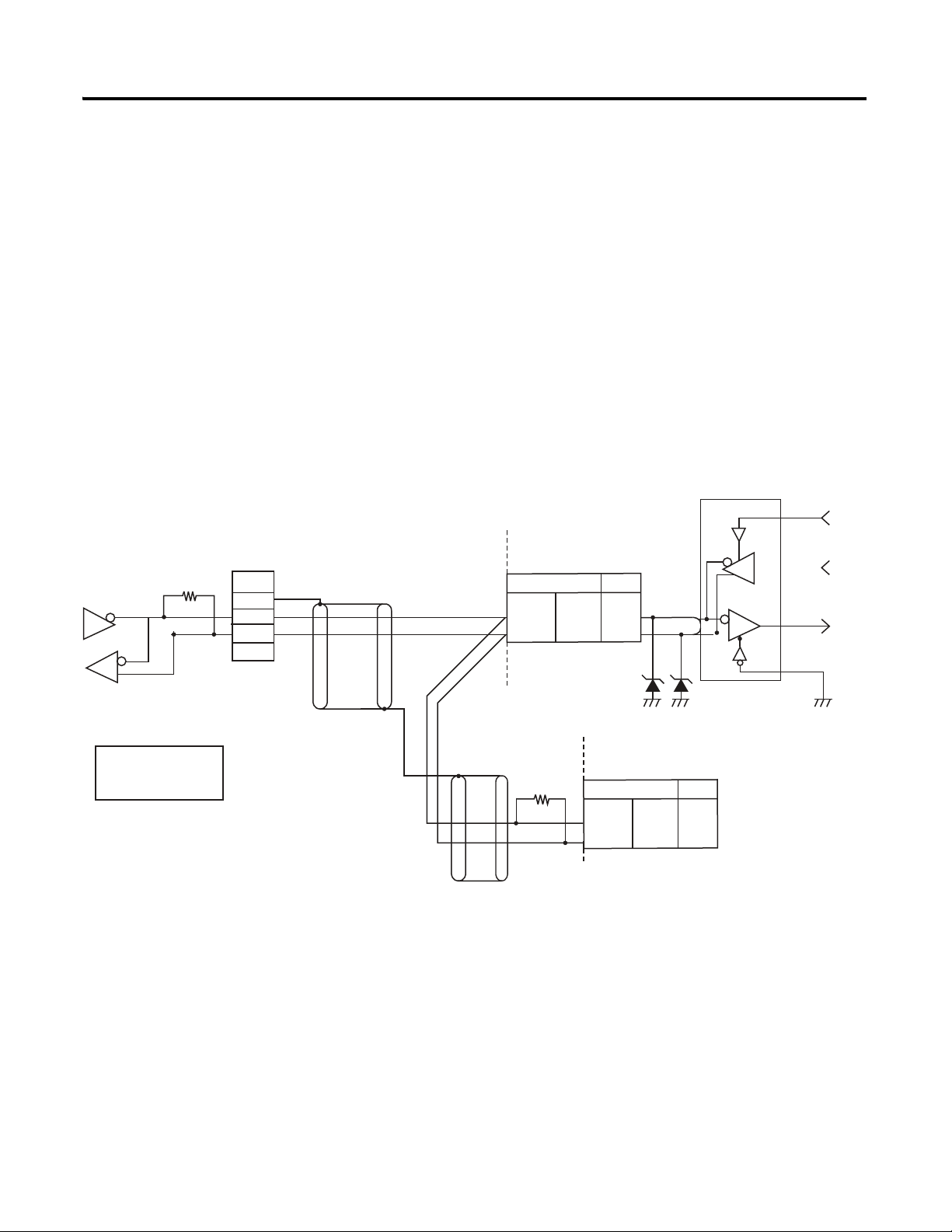
When the host device transmits a command frame, the 900-TCx transmits a
response frame that corresponds to the command frame. A single response
frame is returned for each command frame. The following diagram shows the
operation of the command and response frames.
Command Frame
Host Device
900-TCx Temperature Controller
Response Frame
Command Frame
Allow a wait time of at least 2 ms until the next command is sent after the host
device receives a response from the 900-TCx temperature controller.
Publication 900-UM004D-EN-E - July 2010
Page 11
About Communications Methods 1-3
SG
FG
Abbr
_
+
900-TC32
12118
7
Pin No.
RS-485
RX
TX
Communications Transceiver
6.8V
Terminator
120Ω
(1/2W)
900-TCx
end node
RS-485
Use a terminator of resistance
120Ω = (1/2W)
Shielded cable
Both ends of the transmission line
(including the host device) must be
specified (by setting terminator ON) as
the end node. The total resistance of
the terminators must be at least 54Ω.
A<B: [1] mark
A>B: [0] space
Shielded cable
Host Device
RS-485
900-TC8/16
Abbr
A ( – )
B ( + )
900-TC32
12
11
8
7
Pin No.
900-TC8/16
Abbr
A ( – )
B ( + )
Interface
Wiring
Communications with the host device are carried out through a standard
RS-485 or RS-232C(900-TC8x) interface. Use a cat. no. 900-CONVxx
interface converter for RS232C/USB to RS485 conversion.
RS-485
• RS-485 connections can be 1:1 or 1: N. A maximum of 32 Units
(including the host device) can be connected in one-to-N systems.
• The total cable length is 500 m max.
2
• Use a shielded, twisted-pair cable #24 AWG (0.205 mm
2
(2.081 mm
) for the 900-TC8 and 900-TC16.
• Use a shielded, AWG24 to AWG18 (cross-sectional area of 0.205 to
0.823 mm2) twisted-pair cable for the 900-TC32.
)…#14 AWG
Match the communications specifications of the 900-TCx and the host device.
If a one-to-N system is being used, be sure that the communications
specifications (Refer to Communications Specifications on page 1-2) of all devices
in the system (except individual unit numbers) are the same.
This section explains how to set the 900-TCx's communications specifications.
For details on the host device, refer to publication 900-UM007*.
Publication 900-UM004D-EN-E - July 2010
Page 12
1-4 About Communications Methods
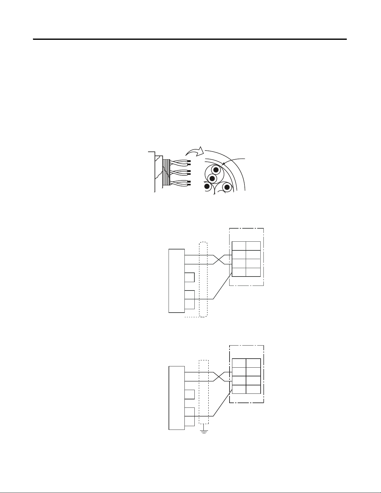
Cable Reference Diagram
900-TCxx
#24 AWG…#14 AWG
Conductor cross-section
0.205 mm to 2.081mm
22
No.
11
12
13
SD
RD
SG
RS-232C
900-TC8
Host Device
RS-232C : 25P
<
>
2
3
4
5
6
7
20
1
SD(TXD)
RD(RXD)
RS(RTS)
CS(CTS)
DR(DSR)
SG
ER(DTR)
FG
>
<
<
>
No.
11
12
13
SD
RD
SG
RS-232C
900-TC8
Host Device
RS-232C : 9P
<
>
3
2
7
8
6
5
4
SD(TXD)
RD(RXD)
RS(RTS)
CS(CTS)
DR(DSR)
SG
ER(DTR)
>
<
<
>
RS-232C (Applies to the 900-TC8 only)
• RS-232C connections are 1:1.
• The total cable length is 15m max.
• Use a shielded, AWG24 to AWG14 (cross-sectional area of 0.205 to
2.081 mm2) twisted-pair cable for the 900-TC8 and 900-TC16.
• Use a shielded, AWG24 to AWG18 (cross-sectional area of 0.205 to
0.823 mm2) twisted-pair cable for the 900-TC32.
Wiring for 25-pin RS-232 connector on host device
Publication 900-UM004D-EN-E - July 2010
Wiring for 9-pin RS-232 connector on host device
Page 13

About Communications Methods 1-5
Communications
parameters
The 900-TCx's communications specifications are set/configured in the
Communications Setting function group. These parameters are set on the
900-TCx's front panel.
The table below shows the communications parameters and their ranges.
Table 1.2 Communication Parameters and Ranges
Parameter Displayed
Characters
Communication protocol psel cwf/mod
Communications unit
number
Baud rate bps 1.2 / 2.4 / 4.8 /
Communications data
length
Communications stop bit sbit 1/2 1/2
Communications parity prty None/even/odd none/even /odd
Send data wait time sdwt 0…99 0…99 ms, default time:
u-no 0…99 0, 1…99
len 7/8(bit) 7/8 (bit)
Setting Range Set Value
(Blue highlighted
characters indicate
defaults)
1 .2 / 2.4 / 4.8 /
9.6 /19.2 / 38.4
/ 57.6 (kbps)
9.6/19.2/38.4/57.6 (kbps)
20 ms
Note: Highlighted values indicate default settings.
The communications data length for Modbus must be 8 bits.
Publication 900-UM004D-EN-E - July 2010
Page 14
1-6 About Communications Methods
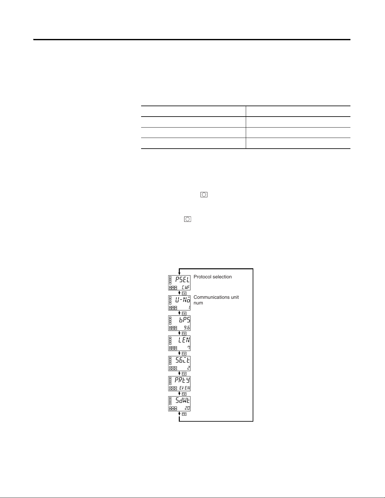
c
psel
cwf
c
u-no
1
c
bps
9.6
c
len
7
c
56it
2
c
prty
eVen
c
sdwt
20
Protocol selection
Communications unit
number
Communications
baud rate
Communications data
length (See note.)
Communications stop
bits (See note.)
Communications
parity
Send data wait time
Communications Parameter
Before you carry out communications with the 900-TCx, set up
communications unit number, baud rate and other parameters by carrying out
Setup
the following procedure. For details of operations other than communications
parameter setup, refer to the applicable 900-TCx User Manual.
Table 1.3 900-TCx User Manuals
Communications Parameter Setup
Temperature Controller Model Number User Manual
900-TC8 900-UM007*
900-TC16 900-UM007*
900-TC32 900-UM007*
1. Hold down the key for at least three seconds to move from the
Operation function group to the Initial Setting function group.
2. Press the key for less than one second to move from the Initial
Setting V to the Communications Setting function group.
Publication 900-UM004D-EN-E - July 2010
3. Select the parameters as shown below by pressing the
4. Use the
D or U keys to change the parameter set values.
M key.
Note: Displayed only when the Protocol Selection is CWF (900-TC)
Page 15

About Communications Methods 1-7
Communication Parameters
Note that communications parameters are enabled after they have been
changed by resetting the controller.
• Protocol Selection (
psel)
The communications protocol can be selected. Set CompoWay/F
(900-TC) or Modbus.
• Communications unit number (
u-no )
This parameter is for setting a unique unit number for each of the
temperature controllers in the system. This unit number is set so that
the host device can identify the temperature controller when
communications are carried out with the host device. Set a unit number
within the range 0 to 99 for each temperature controller connected to
the host device on the network. Default is “1”. When two or more
temperature controllers are used, do not set them to the same unit
number Doing so will prevent normal communications operation.
• Baud rate (
bps)
This parameter is for setting the baud rate when communicating with
the host device. Set one of "1.2 (1200 bps)", "2.4 (2400 bps)", "4.8 (4800
bps)", "9.6 (9600 bps)", "19.2 (19200 bps)", "38.4 (38400 bps)", or
“57.6 (57600 bps)➊”. All units must be set to the same baud rate.
• Communications data length {
len )
This parameter is for setting the communications data length. Set either
of "7 bits" or "8 bits". All units must be set to the same communications
data length.
• Communications stop bit (
sbit )
This parameter is for setting the communications stop bit. Set either of
"1" or "2". All units must be set to the same communications stop bit
value.
• Communications parity (
prty)
This parameter is for setting the communications parity. Set one of
"none", "even" or "odd". All units must be set to the same
communications parity value.
• Send Data Wait Time (
sdwt)
The send data wait time can be set in 1-ms increments between 0 and
99 ms. The default is 20 ms.
➊ Offered with 900-TC8, 900-TC16, and 900-TC32 Series B controllers.
Publication 900-UM004D-EN-E - July 2010
Page 16

1-8 About Communications Methods
Setting Communications
Writing
Set the communications writing parameter to ON to allow the host to write to
the 900-TCx controller(s) via communications.
Parameter Setting
1. Press the key for less than one second to move from the operation
level tot he adjustment level.
2. Select the parameters as shown below by pressing the
3. Use the
D or U keys to set the communications writing parameter to
ON.
c
l.adj
c
c
cmwt
c
cmwt
Adjustment Level
Display
Displayed only once when
entering adjustment level.
AT Execute/Cancel
at
off
Communications
Writing
off
on
•
•
•
•
M key.
Publication 900-UM004D-EN-E - July 2010
Page 17

Chapter
STX
Node No.
12 2
Sub-address
0 00
SID
1
BCC Calculation Range
Tex t
Command Text
ETX
BCC
1
1
2
Bulletin 900 Communications Procedures 900-TCx (CompoWay/F)
Data Format
Unless otherwise indicated, numbers in this manual are expressed in
hexadecimal (with an H’ before the number: e.g., H’02). Values without the H’,
such as 00, are ASCII. The number underneath each delimiter in a frame
indicates the number of bytes.
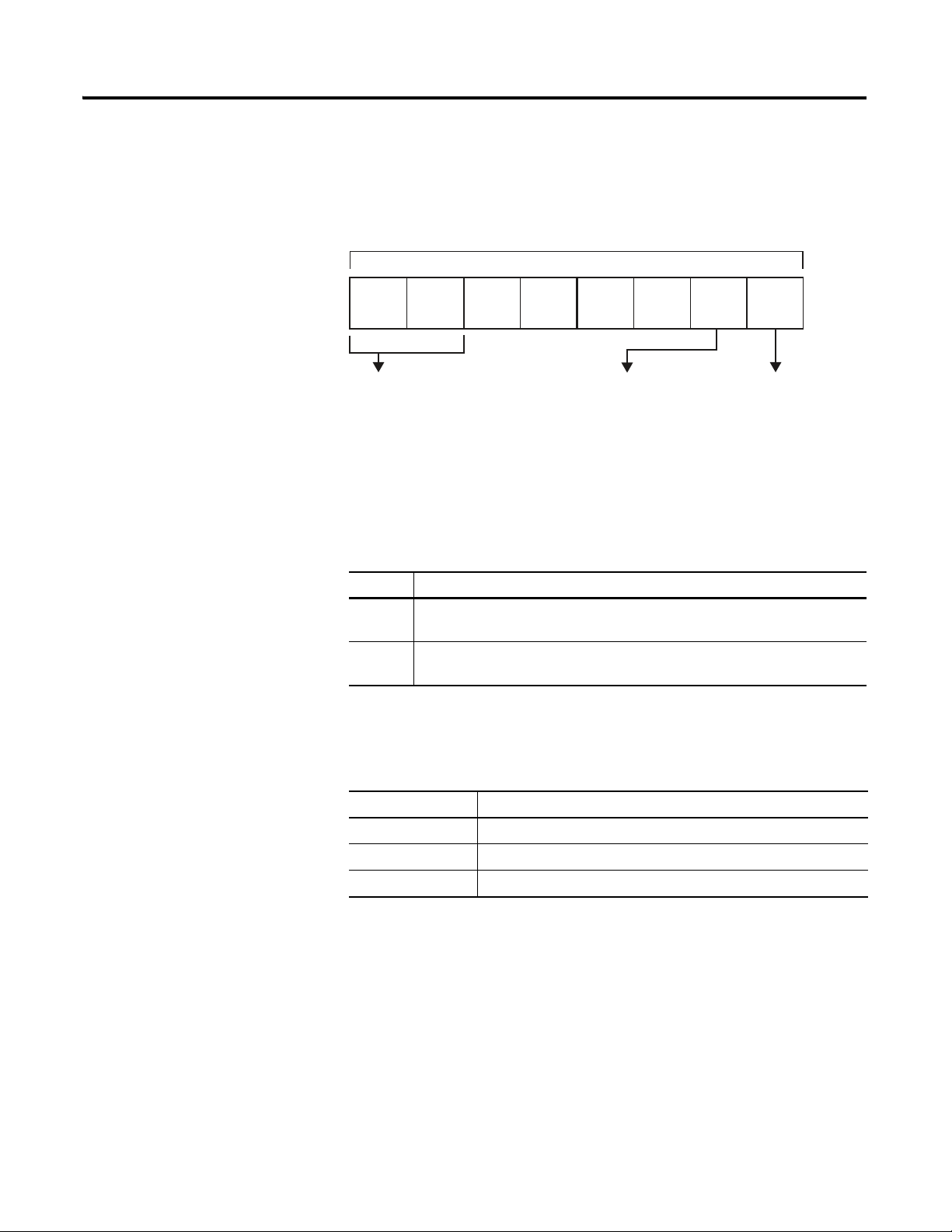
Command Frame
Table 2.1
STX This code (H’02) indicates the beginning of the communications frame
(text). Always set this character in the first byte. When STX is received
again during reception, reception is carried out again from the point
where STX was received.
Node number • This number specifies the transmission’s destination.
• Specify the 900-TCx’s communication unit number.
• A BCD value between 00 and 99 or an ASCII value of XX can be set.
• Specify XX for a broadcast transmission. No responses will be
returned for broadcast transmissions.
• No responses will be returned from node numbers other than the
ones in the above range.
Sub-address This is not used on the 900-TCx. Be sure to set the sub-address to 00.
SID (service ID) This is not used on the 900-TCx. Be sure to set the Service ID to 00.
Command text Command text area. Refer to Structure of Command Text on page 2-5
ETX This code (H’03) indicates the end of the text.
BCC Block Check Character The BCC result is found by calculating the
exclusive OR of the bytes from the node number up to ETX.
2-1 Publication 900-UM004D-EN-E - July 2010
BCC Calculation Example
The BCC (Block Check Character) is determined by calculating the exclusive
OR of the bytes from the node number up to ETX. The 8-bit result is written
to the BCC byte at the end of the frame.
STX Node No. Sub-address SID Command Text ETX BCC
02H 0(30H) 0(30H) 0(30H) 0(30H) 0(30H) 0(30H) 5(35H) 0(30H) 3(33H) 03H 35H
BCC=30H⊕30H⊕30H⊕30H⊕30H⊕30H⊕35H⊕30H⊕33H⊕03H=35H
Calculation result 35H is set to the BCC area.
The
⊕
symbol indicates exclusive OR operation and the H indicates hexidecimal code.
Page 18

2-2 Bulletin 900 Communications Procedures 900-TCx (CompoWay/F)
Command Text BCC
ETX
1 1
222
End CodeSub-addressNode No.
STX
1
Response Frame
Table 2.2
End
Name Description Error
Code
00 Normal
The command ended normally without error. None
completion
0F FINS
command
error
The specified FINS command could not be executed.
The FINS response code should indicate why the
command could not be executed.
10 Parity error The sum total of bits whose received data is 1 does
not match the set value of Communications Parity.
11 Framing
Stop bit is 0. 1
error
12 Overrun
error
An attempt was made to transfer new data when the
reception data was already full.
13 BCC error The calculated BCC value is different from the
received BCC value.
14 Format error • The command text contains characters other than
0 to 9, and A to F. This error is not applicable to
the echoback test. (For details, see Refer
to Echoback Test on page 2-17)
• No SID and command text. Or, no command text
• MRC/SRC not included in command text
16 Sub-address
error
• Illegal (unsupported) sub-address
• No sub-address, SID and command text
• Sub-address less than two characters, and no SID
and command text
Detection
Priority
8
2
3
5
7
6
Publication 900-UM004D-EN-E - July 2010
18 Frame
length error
The received frame exceeds the fixed (supported)
number of bytes.
• The end code is returned for each command frame that was addressed
to the local node.
• No response will be returned unless the frame contained all elements up
to the ETX and BCC.
• “Error Detection Priority” indicates the priority when two or more
errors occur simultaneously.
4
Page 19

Bulletin 900 Communications Procedures 900-TCx (CompoWay/F) 2-3
STX
Node No. Sub-address SID BCC
0 00ETX
BCC
ETX
End Code
410
Sub-address
0
Node No.
STX
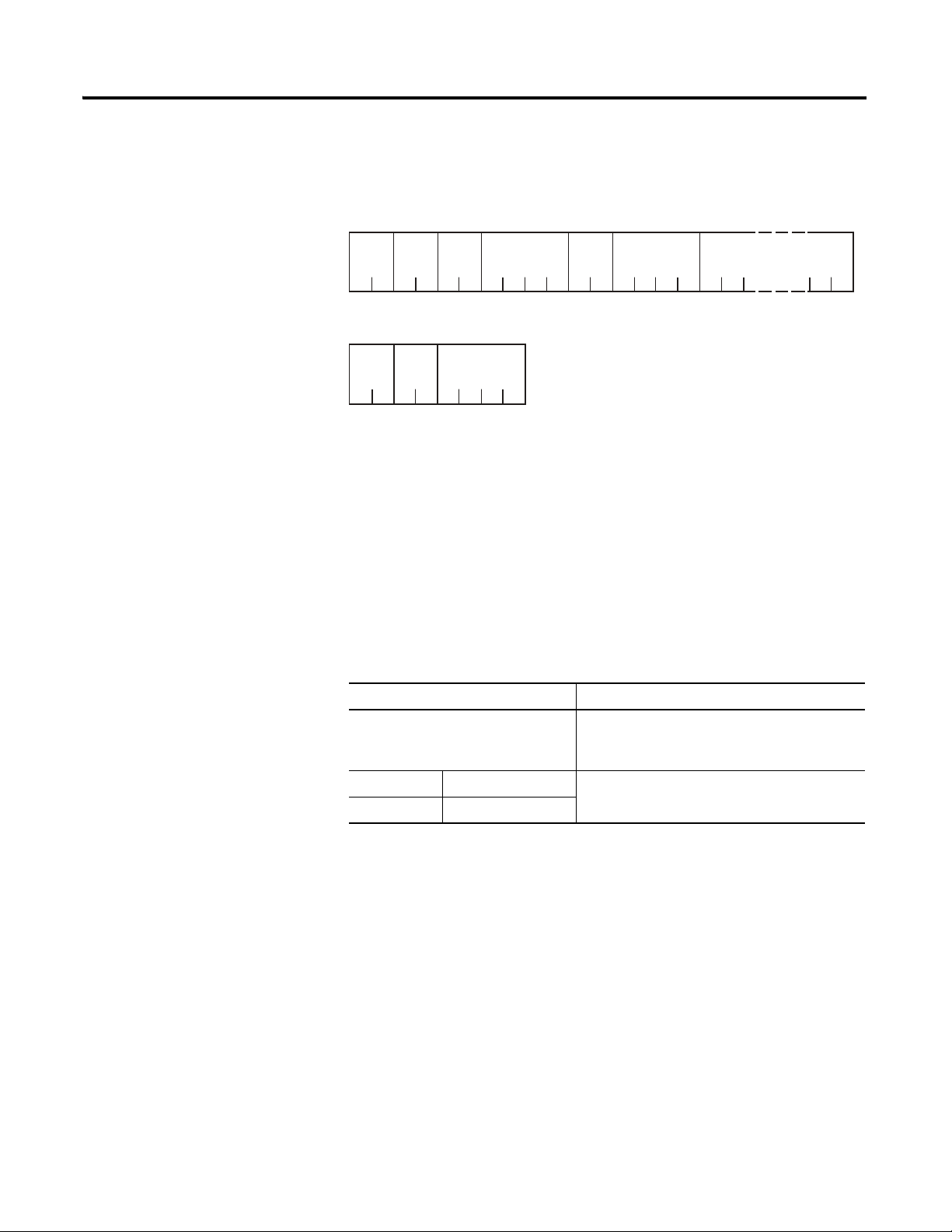
Communications Data
Table 2.3 Communications Data
Communications
Specifications
CompoWay/F
(Bulletin 900-TCx)
Set (Monitor)
Value
8 digits (Hex) 2's complement Decimal point is removed and
Minus Value Decimal Point
the result is converted to
hexadecimal. Example: 105.0
Æ 1050 Æ H’000041A
Example of End Code
The following examples show an end code when a command did not end
normally.
Example 1: Illegal sub-address, and no SID and command text
Command Format:
Node No. Sub-address BCC
STX 0 A ETX
Response Format:
BCC
STX
Node No.
Sub-address
A0
End Code
16
ETX
End code is "16" (sub-address error).
This is because a sub-address was received and the sub-address error has a
higher error detection priority than the format error.
Example 2: No command text
Command Format:
Response Format:
End code is 14 (format error).
Publication 900-UM004D-EN-E - July 2010
Page 20

2-4 Bulletin 900 Communications Procedures 900-TCx (CompoWay/F)
No response
BCC
ErrETXSTX
Node No.
BCC
ETX
End Code
13
Sub-address
00
Node No.
STX
Example 3: No node number provided
Command Format:
The node number is lacking one character.
Response Format:
Example 4: No sub-address, and illegal BCC
Command Format:
BCC
ETXSTX
Response Format:
Sub-address is 00 and end code is 13 (BCC error).
Publication 900-UM004D-EN-E - July 2010
Page 21

Bulletin 900 Communications Procedures 900-TCx (CompoWay/F) 2-5
MRC SRC MRES SRES Data
MRC SRC MRES SRES
Structure of Command Text
PDU (Protocol Data Unit) Structure
An MRC (Main Request Code) and SRC (Sub-Request Code) followed by the
various required data is transferred to the command text.
Service request PDU
MRC SRC Data
The MRES (Main Response Code) and SRES (Sub-Response Code) are
transferred to the response frame following the above MRC/SRC. Data is then
transferred following the MRES and SRES.
Service response PDU (during normal operation)
If the specified command text could not be executed, the service response
PDU will contain only MRC/SRC and MRES/SRES.
Service response PDU (command text not executed)
MRES/SRES provides the response code. MRES/SRES are not output when
processing ends in a normal operation.
Area Definitions
Areas comprise only the variable area.
Publication 900-UM004D-EN-E - July 2010
Page 22
2-6 Bulletin 900 Communications Procedures 900-TCx (CompoWay/F)
MSB LSB
0000
Type Code (Variable Type)
The following defines variable area type codes.
Variable type (1 byte)
Access size Area Read/Write
11: Double-word 0: Setup area 0 0: Read only
10: Word 1 : Setup area 1 1 : Read/write
The following table summarizes setup areas 0 and 1.
Table 2.4
Area Description
Setup
area 0
Setup
area 1
This area groups together the Protect, Manual Control, Operation and
Adjustment function groups.
This area groups together the Initial Setting, Communications Setting,
Advanced Function Setting and Calibration function groups.
The variable type is converted to 2-byte ASCII code and loaded to the frame.
The following table shows available variable types.
Table 2.5
Variable Type Description
CO/80 R/O (read only) parameter for setup area 0.
C1/81 R/W parameter for setup area 0.
C3/83 R/W parameter for setup area 1 .
Note: Setup area 1 has no R/O (read only) parameters. Therefore, variable
type C2 does not exist.
Addresses
Each of the variable types is appended with an address. Express addresses in
2-byte hexadecimal code, and append for the specified access size.
Publication 900-UM004D-EN-E - July 2010
Page 23

Bulletin 900 Communications Procedures 900-TCx (CompoWay/F) 2-7
Number of Elements
The number of elements is expressed in 2-byte hexadecimal code. The range
that can be specified for the number of elements depends on the command.
Refer to Detailed Description of Services on page 2-8.
List of Services
Table 2.6
MRC SRC Name of Service Process
01 01 Read from variable
area
01 02 Write to variable area This service writes to variable areas.
01 04 Composite Read from
Variable Area
01 13 Composite Write to
Variable Area
This service reads from variable areas.
This service reads from the variable area in
the order specified by the parameters.
This service writes to the variable area in the
order specified by the parameters.
05 03 Read Controller
Attributes
06 01 Read controller status This service reads the run status of the
08 01 Echoback test This service carries out the echoback test.
30 05 Operation instructions This service carries out run/stop,
This service reads the model number and
communications buffer size.
controller.
communications writing, write mode, save
RAM data, AT (auto-tuning) execution/cancel,
multi-SP, move to protect function, move to
setup area 1 and software reset.
Note: No commands will be accepted and no responses will be returned when
a memory error (RAM error) has occurred or the controller is initializing (until
the controller recognizes the process value after the power is turned ON).
Publication 900-UM004D-EN-E - July 2010
Page 24
2-8 Bulletin 900 Communications Procedures 900-TCx (CompoWay/F)
Read Data
(for number of elements)
Response
Code
4
SRC
2
MRC
2
0101
Service Response PDU:
Service Request PDU:
MRC2SRC
22 2
0101
Variable
Type
Read Start
Address
4
Bit
Position
Number of
Elements
4
00
Number of elements X 8 or 4
Detailed Description of
Services
Read from Variable Area
This service reads from variable areas.
• Variable Type and Read Start Address
For details on Variable Types and Read Start Addresses, refer to Chapter
3, Communications Data.
• Bit position
Bit accessing is not supported on the 900-TCx. It is fixed to 00.
• Number of elements
Table 2.7
Number of Elements Process
0000 The read operation is not performed (read data is
not appended to the service response PDU), and
processing ends in normal completion.
Double word 0001…0019 (1…25) The read operation is carried out, and processing
Word 0001…0032 (1…50)
ends in normal completion.
Publication 900-UM004D-EN-E - July 2010
Page 25
Response code
ATTENTION
!
Normal Completion
Table 2.8
Bulletin 900 Communications Procedures 900-TCx (CompoWay/F) 2-9
Response
Code
0000 Normal completion No errors were found.
Error Occurred
Table 2.9
Response
Code
1001 Command too long The command is too long.
1002 Command too short The command is too short.
1101 Area type error The variable type is wrong.
1103 Start address out-of-range error The read start address is out of range.
110B Response too long The number of elements exceeds the
1100 Parameter error The bit position not 00.
2203 Operation error EEPROM error
Name Description
Error Name Cause
maximum/
Alarm function:
Even though alarms are not displayed on the controller's
display, they function normally in communications.
Publication 900-UM004D-EN-E - July 2010
Page 26
2-10 Bulletin 900 Communications Procedures 900-TCx (CompoWay/F)
Write to Variable Area
This service writes to the controller’s variable areas.
Service Request PDU:
MRC SRC
002
1
2
Variable
Type
22
Write Start
Address
4
Bit
Position
00
2
Number of
Elements
4
Write Data
(for number of elements)
Number of elements x 8 or 4
Service Response PDU:
MRC SRC Response
0 012
22 4
Code
• Variable Type and Write Start address
For details on variable types and write start addresses, refer to Chapter 3,
Communications Data.
• Bit position
Bit accessing is not supported on the 900-TCx controller. Fixed to 00.
• Number of elements
Table 2.10
Number of Elements Process
0000 The write operation is not performed (do not
append write data to the service request PDU)
and processing ends in normal completion.
Double word 0001…0018 (1…24) The write operation is performed and processing
Word 0001…0030 (1…48)
ends in a normal completion.
Publication 900-UM004D-EN-E - July 2010
Page 27
Bulletin 900 Communications Procedures 900-TCx (CompoWay/F) 2-11
ATTENTION
!
Response code
Normal Completion
Table 2.11
Response Code Name Description
0000 Normal completion No errors were found.
Error Occurred
Table 2.12
Response Code Error name Cause
1002 Command too short The command is too short.
1101 Area type error Wrong variable type
1103 Start address
out-of-range error
1104 End address
out-of-range error
1003 Number of elements/
data mismatch
Write start address is out of range.
The write end address (write start address
+ number of elements) exceeds the final
address of the variable area.
The number of data does not match the
number of elements.
1100 Parameter error • Bit position is other than 00.
• Write data is out of range.
3003 Read-only data Variable type CO was written to.
2203 Operation error • The Communications Writing
parameter is set to OFF (disabled).
• Attempted to write to a parameter in
setup area 1 from setup area 0.
• Attempted to write to a protect
parameter from other than protect
group.
• AT (auto-tuning) was in progress. See
note.
• EEPROM error.
Note: For details on AT (auto-tuning), see publication 900-UM007*.
Alarm function:
Even though alarms are not displayed on the
controller's display, they are all functional in
communications.
Publication 900-UM004D-EN-E - July 2010
Page 28
2-12 Bulletin 900 Communications Procedures 900-TCx (CompoWay/F)
MRC SRC
0104 00
22224
00
224
Variable
type
Read
address
Bit position
Variable
type
Read
address
Bit
position
Variable
type
Response code
Variable
type
Read data
22
MRC
SRC
0104
4
Number of elements ×8 or 4
2
2
Read data
Number of elements ×8 or 4
Composite Read from Variable Area
This service reads in order the contents of specified addresses in the variable
area.
Service Request PDU
Service Response PDU
Note: The read data is read together with the variable type in the order specified by the command.
Variable Type and Read Start Address
For details on variable types and read start addresses, Refer
to Communications Data on page 2-3.
Bit Position
The 900-TCx controllers do not support bit access. Fixed to “00.”
Number of Read Data Items (Variable Type + Read Data)
Table 2.13
Read Data Length Number of Read Data Items
For double word 20 max.
For word 25 max.
Response Code
Publication 900-UM004D-EN-E - July 2010
Normal completion
Page 29
Bulletin 900 Communications Procedures 900-TCx (CompoWay/F) 2-13
Variable
type
Write
address
Variable
type
Write data
22
MRC
SRC
0113
00
224
00
224
Write data
Write
address
Bit position
Bit
position
Number of elements ×8 or 4
Number of elements ×8 or 4
MRC SRC
0113
22 4
Response
code
Table 2.14
Response Code Name Description
0000 Normal Completion No errors were found.
Error occurred
Table 2.15
Response Code Name Description
1002 Command too short The command is too short.
1101 Area type error The variable type is wrong.
110B Response too long
1100 Parameter error Bit position is not “00”.
2203 Operation error EEPROM error.
The number of elements
exceeds the maximum.
Composite Write to Variable Area
This service reads in order the contents of specified addresses in the variable
area.
Service Request PDU
Service Response PDU
Variable Type and Write Start Address
For details on variable types and read start addresses, Refer
to Communications Data on page 2-3.
Bit Position
The 900-TCx controllers do not support bit access. Fixed to “00.”
Publication 900-UM004D-EN-E - July 2010
Page 30
2-14 Bulletin 900 Communications Procedures 900-TCx (CompoWay/F)
Number of Write Data Items (Variable Type + Write Data)
Table 2.16
Read Data Length Number of Read Data Items
For double word 12 max.
For word 17 max.
Response Code
Normal completion
Table 2.17
Response Code Name Description
0000 Normal Completion No errors were found.
Error occurred
Table 2.18
Response Code Name Description
1002 Command too short The command is too short.
1101 Area type error The variable type is wrong.
• Bit position is not “00”.
1100 Parameter error
3003 Read-only error
2203 Operation error
• The write data is out of the
setting range.
Variable type “CO” was written
to.
• The Communications
Writing parameter is set to
“OFF” (disabled).
• Attempted to write to a
parameter in setup area 1
from setup area 0.
• Attempted to write to a
protect parameter from
other than the protect
group.
• AT (auto-tuning) was in
progress. See note.
• EEPROM error
Publication 900-UM004D-EN-E - July 2010
Note: For details on AT (auto-tuning), see publication 900-UM007*.
Page 31

Bulletin 900 Communications Procedures 900-TCx (CompoWay/F) 2-15
MRC SRC
0503
22
MRC SRC
0503 00D9
22 4 10 4
Response
code
Model No.
Buffer
size
Read Controller Attributes
This service reads the model number and communications buffer size.
Service Request PDU
Service Response PDU
Model Number
The model number is expressed in 10-byte ASCII. When 10 bytes are
not required, pad the remaining bytes with spaces.
Buffer Size
The communications buffer size is expressed in 2-byte hexadecimal, and
read after being converted to 4-byte ASCII.
Buffer size: 40 bytes (= H’0028)
217 bytes (= H’00D9) (900-TC8, 900-TC16,
and 900-TC32 Series B)
Response Code
Normal Completion
Table 2.19
Response Code Name Description
0000 Normal completion No errors were found.
Error Occurred
Table 2.20
Response Code Name Description
1001 Command too long The command is too long.
2203 Operation error EEPROM error.
Publication 900-UM004D-EN-E - July 2010
Page 32

2-16 Bulletin 900 Communications Procedures 900-TCx (CompoWay/F)
Read Controller Status
This service reads the operating and error status of the controller.
Service Request PDU
MRC SRC
0 061
2 2
Service Response PDU
MRC SRC Response
0
6
0
22 4 22
Code
1
Run
Status
Related
Informa-
tion
Publication 900-UM004D-EN-E - July 2010
Page 33

Bulletin 900 Communications Procedures 900-TCx (CompoWay/F) 2-17
Operating status
Table 2.21
Run Status Description
00 Control is being carried out (error has not occurred in setup area 0, and the
controller is running).
01 Control is not being carried out (state other than above).
Related information
7654 3210
0
Bit position
Heater overcurrent (CT1)
Heater current hold (CT1)
AD converter error
Heater overcurrent (CT2)
Heater current hold (CT2)
Display range exceeded
Input error
Response Code
Normal Completion
Table 2.22
Response Code Name Description
0000 Normal completion No errors were found.
Error Occurred
Table 2.23
Response Code Name Description
1001 Command too long The command is too long.
2203 Operation error EEPROM error
Echoback Test
This service carries out the echoback test
Service Request PDU
MRC SRC Test Data
0081
2 2 0 to 200
Publication 900-UM004D-EN-E - July 2010
Page 34

2-18 Bulletin 900 Communications Procedures 900-TCx (CompoWay/F)
Service Response PDU
MRC SRC Response
Code
0801
22
Test Data
0 to 200
Test data
Set any test data within the range 0…200 bytes of user-defined test data.
Set a value for the test data within the ranges shown below according to
the communications data length.
Table 2.24
Communications Data Length Test Data
8 bits ASCII data: H’20 to H’7E, or H’A1 to H’FE
7 bits ASCII data: H’20 to H’7E
Do not set H’40. Doing so results in no response.
Response code
Normal Completion
Table 2.25
Response Code Name Description
0000 Normal completion No errors were found.
Error Occurred
Table 2.26
Response Code Name Description
1001 Command too long The command is too long.
2203 Operation error EEPROM error.
Publication 900-UM004D-EN-E - July 2010
Page 35

Bulletin 900 Communications Procedures 900-TCx (CompoWay/F) 2-19
MRC SRC
3005
22 4
Response
code
Operation Commands
This service performs operations like the following:
• Communications Writing
•RUN/STOP
•Multi-SP
• AT Execute/Cancel
•Write Mode
•Save RAM Data
• Software Reset
• Move to Setup Area 1
Service Request PDU
Related
MRC SRC
3005
2222
Command
code
informa-
Service Response PDU
• Move to Protect Group
•Auto/Manual Switch
• Parameter Initialization
• Alarm Latch Cancel
• Invert Direct/Reverse
Operation
• Program Start
tion
Publication 900-UM004D-EN-E - July 2010
Page 36

2-20 Bulletin 900 Communications Procedures 900-TCx (CompoWay/F)
Command Code and related information
Table 2.27
Command
Code
00 Communications writing 00: OFF (disabled)
01 RUN/STOP 00: Run
02 Multi-SP 00: Set point 0
03 AT execute/cancel 00: AT Cancel
04 Write mode 00: Backup mode
05 Save RAM data 00
06 Software reset 00
07 Move to setup area 1 00
08 Move to protect function
09 Auto/manual switch 00: Automatic mode
Description Related Information
01: ON (enabled)
01 : Stop
01 : Set point 1
02: Set point 2
03: Set point 3
01 : 100% AT execute
02: 40% AT execute
01 : RAM write mode
00
group
01: Manual mode
0B Parameter initialization 00: Initialize to defaults
0C Alarm Latch Cancel 00: Alarm 1 latch cancel
01: Alarm 2 latch cancel
02: Alarm 3 latch cancel
03: HB alarm latch cancel
04: HS alarm latch cancel
05: OC alarm latch cancel
0F: All alarm latch cancel
0E Invert Direct/Reverse
Operation
11 Program start 00: Reset
00: Not invert
01: Invert
01: Start
Response code
Normal Completion
Table 2.28
Response
Code
0000 Normal completion No errors were found.
Name Description
Publication 900-UM004D-EN-E - July 2010
Page 37

Error Occurred
Table 2.29
Bulletin 900 Communications Procedures 900-TCx (CompoWay/F) 2-21
Response
Code
1001 Command too long The command is too long.
1002 Command too short The command is too short.
1100 Parameter error Instruction code and related information are wrong.
2203 Operation error • The Communications Writing parameter is
Error name Cause
set to OFF (disabled). However, note that the
error is accepted regardless of the
Communications Writing parameter setting
(ON/OFF).
• The command cannot be processed. For
details, refer to Description of operating
instructions and precautions information below.
• EEPROM error
Description of operation commands and precautions:
• Communications Writing
Set the Communications Writing parameter to “ON: enabled” or “OFF:
disabled” with the related information setting. The setting can be
accepted in both setup area 0 and setup area 1. An operation error will
occur, however, if enabling or disabling communications writing is set
for an event input.
• RUN/STOP
Set control to “run” or “stop” with the related information setting. The
setting can be accepted in both setup area 0 and setup area 1. An
operation error will occur, however, if RUN/STOP is set for an event
input.
•Multi-SP
Set four set points beforehand in the Adjustment group so that you can
switch to a desired set point. The setting can be accepted in both setup
Publication 900-UM004D-EN-E - July 2010
Page 38

2-22 Bulletin 900 Communications Procedures 900-TCx (CompoWay/F)
area 0 and setup area 1. An operation error will occur in the following
situations.
– When AT is being executed.
– When the Multi-SP Uses parameter is set to OFF.
– When the Multi-SP Uses parameter is set to ON but multi-SP is set
for an event input (Number of Multi-SP Uses > 0).
• AT Execute/Cancel
Set AT (auto-tuning) to “execute” or “cancel” with the related
information setting. This command can be accepted in setup area 0 only.
An “operation error” will be generated in the following instances:
– When the RUN/STOP parameter is set to “stop”
– When the command is executed in “setup area 1”
– When ON/OFF control is being used
– When 40% AT is specified during 100% AT execution.
– When 100% AT is specified during 40% AT execution.
In addition, a parameter error will occur if 40% AT is specified during
heating and cooling control.
Note: If the same type of AT execution is specified during AT execution
(e.g., if 100% AT is specified during 100% AT execution), the AT will
not be restarted and the operation will end in normal completion with
no processing.
•Write Mode
Set either the backup mode or RAM write mode with the related
information setting. The setting can be accepted in both setup area 0
and setup area 1.
The number of EEPROM (non-volatile memory) write operations is
limited. Therefore, use RAM write mode when frequently overwriting
data.
Table 2.30
Write Mode Description
The data is written to EEPROM when the parameters in the
Backup mode
RAM write mode
operation/adjustment levels (excluding read-only parameters)
are written by communications.
The data is not written to EEPROM when the parameters in the
operation/adjustment levels (excluding read-only parameters)
are written by communications. Parameters can be changed by
operating the keys on the front panel of the controller.
Publication 900-UM004D-EN-E - July 2010
Page 39

Bulletin 900 Communications Procedures 900-TCx (CompoWay/F) 2-23
– When the mode is switched from RAM write mode to backup mode,
the parameters in the Operation/Adjustment groups (excluding
read-only parameters) are written to EEPROM.
– The RAM write mode is enabled only when the Communications
Writing parameter is set to “ON” (enabled). Consequently, when the
Communications Writing parameter setting is changed to “OFF”
(disabled), the parameters in the Operation/Adjustment groups
(excluding read-only parameters) are written to EEPROM even if the
mode is set to RAM write mode.
•Save RAM Data
This command writes the parameters in the Operation/Adjustment
groups (excluding read-only parameters) to EEPROM. The setting can
be accepted in both setup area 0 and setup area 1.
• Software Reset
Restarts processing from the point when power is turned ON. The
setting can be accepted in both setup area 0 and setup area 1.
• Move to Setup Area 1
This command moves to “setup area 1” and can be accepted at both
setup areas 0 and 1. If the “Initial Setting/Communications Protect”
parameter is set to “2,” an “operation error” will be generated, and the
move to setup area 1 will be prohibited.
When this move is carried out from setup area 0, the display indicates
the Input Type parameter in the “Initial Setting group.” When this
operation command is executed in setup area 1, the display will not
change.
• Move to Protect Group
This command moves to the “Protect group” and can be accepted only
in setup area 0.When this command is issued in setup area 1, an
“operation error” will be generated, and the move to the protect level
will be prohibited.
• Moving to Protect Group in Manual Mode
When this operation command is issued in manual mode, an
“operation error” will be generated, and the move to the Protect
group will be prohibited.
•Auto/Manual Switch
This operation command switches the mode to manual mode or
automatic mode, based on the related information setting. This
command can be accepted in setup area 0 only. An “operation error”
will be generated in the following instances:
– When the command is executed in “setup area 1"
– When auto/manual switching is disabled (not displayed)
When the Controller is switched to manual mode, the “manual
manipulated variable” will be displayed. When the Controller is switched
from manual mode to automatic mode, the Operation group’s first
parameter will be displayed. When the Controller is switched to manual
Publication 900-UM004D-EN-E - July 2010
Page 40

2-24 Bulletin 900 Communications Procedures 900-TCx (CompoWay/F)
mode while already in manual mode, the command will be completed
normally and the display will not change (the contents will not be
refreshed).
• Writing Auto/Manual Status in EEPROM
The write mode determines whether the auto/manual status is written
to EEPROM.
Table 2.31
Write Mode Description
Backup mode
RAM write mode
Note: When the auto/manual mode is switched with an operation
command through communications and the Controller is in RAM write
mode, the auto/manual status is not stored in EEPROM. Consequently,
if the Controller is restarted by performing a software reset or turning
the power OFF and ON again, the auto/manual mode is set to the last
saved status.
When the auto/manual mode is switched by communications,
the auto/manual status is written to EEPROM.
When the auto/manual mode is switched by communications,
the auto/manual status is not written to EEPROM.
The status can be written with the Controller key operation.
• Switching to Manual Mode during Auto-tuning
If the mode is switched during auto-tuning (AT), the AT will be
cancelled and the Controller will be switched to manual mode.
• Parameter Initialization
The present settings are returned to the default values and written to
EEPROM. This command can be accepted in setup area 1 only. When
this command is issued in setup area 0, an “operation error” will be
generated.
• Alarm Latch Cancel
Table 2.32
Related Information Explanation (Initialization Values)
Default initialization values (Refer to Communications Data on
00
page 2-3 for details.)
(These settings are the same as the ones used when “FACT” is
selected for the setting data’s set value initialization.)
The applicable alarm latch can be cleared with the related information
setting. The setting can be accepted in both setup area 0 and setup area
Publication 900-UM004D-EN-E - July 2010
Page 41

Bulletin 900 Communications Procedures 900-TCx (CompoWay/F) 2-25
Powe r O N
Software reset command
Setting area 0 Setting area 1
“Move-to-setting
area 1” command
Control in progress Control stopped.
1. An operation error will occur if communications writing is disabled or
if an EEPROM error occurs.
• Invert Direct/Reverse Operation
Inverting or not inverting direct/reverse operation can be selected with
the related information setting. The setting can be accepted in both
setup area 0 and setup area 1. The related information specifications are
written to EEPROM according to the write mode settings. An operation
error will occur in the following situations:
– When AT is being executed.
– When inverting direct/reverse operation is set for an event input.
– When executed in manual mode.
•Program Start
The simple program function can be reset/started with the related
information setting. The setting can be accepted in both setup area 0
and setup area 1. An operation error will be generated if program start
has been set in the event input.
•Setting Areas
Control operation is executed in setting area 0. In this state, you can
perform operations that are permitted only during control or those that
cause no problems even if control is in progress. These operations
include reading PVs, writing SPs, and change RUN/STOP status.
Setting area 0, however, prohibits operations that affect control,
including writing data at the initial setting level. (Reading setting data is
always allowed.)
In setting area 1, control operation is stopped. In this state, you can
perform operations that are not allowed in setting area 0. These
operations include writing data at the initial setting level.
At power-ON, the Temperature Controller is set in setting area 0. To
move to setting area 1, use the “move-to-setting area 1” command. To
return to setting area 0, turn the power OFF and ON again, or use the
“software reset” command.
Publication 900-UM004D-EN-E - July 2010
Page 42

2-26 Bulletin 900 Communications Procedures 900-TCx (CompoWay/F)
Response Code List
Normal Completion
Table 2.33
Response
Code
0000 Normal completion No errors were found. None
Name Description Error Detection
Error Occurred
Table 2.34
Response
Code
0401 Unsupported command The service function for the relevant command is not supported. 1
1001 Command too long The command is too long. 2
1002 Command too short The command is too short. 3
1101 Area type error Wrong variable type. 4
1103 Start address out-of-range
1104 End address out-of-range
1003 Number of elements/data
110B Response too long The response length exceeds the communications buffer size (when the
Name Description Error Detection
The read/write start address is out of range. 5
error
The write end address (write start address + number of elements) exceeds
error
mismatch
the final address of the variable area.
The amount of data does not match the number of elements. 7
number of elements is greater than the maximum number of elements for
that service).
Priority
Priority
6
8
1100 Parameter error • Bit position is not “00.”
• The write data is out of the setting range.
• The command code or related information in the operation command
is wrong.
3003 Read-only error Variable type “C0” was written to. 10
2203 Operation error • The Communications Writing parameter is set to “OFF” (disabled).
• Attempted to write to a parameter in setup area 1 from setup area 0.
• Attempted to write to a protect parameter from other than the protect
level.
• Writing was carried out during AT execution.
• Processing is not possible by operation command.
• EEPROM error.
Publication 900-UM004D-EN-E - July 2010
9
11
Page 43

Communications Data
Chapter
3
Variable Area (setup range)
List
This chapter lists the details of each of the communications data in the Bulletin
900-TCx communications procedures.
For communications using a variable type not enclosed in parentheses in the
following table, the set value is double-word data (8 digits). For
communications using a variable type enclosed in parentheses, the set value is
single-word data (4 digits).
For example, variable type C0 is double-word data (8 digits), and
variable type 80 is single-word data (4 digits).
Items expressed in hexadecimal in the “Set (monitor) value” column are the
setting range for CompoWay/F (900-TC) communications. The values in
parentheses are the actual setting range.
For details of variable areas that are described not in numerical values but by
text, refer to the relevant parameter descriptions. For details concerning the
operation of these controller parameters, refer to the applicable user manual
for the specific controller (See Table 1.3 on page 1-6).
3-1 Publication 900-UM004D-EN-E - July 2010
Page 44

3-2 Communications Data
Table 3.1 Variable Type C0 (80)
Variable
Ty pe
C0 (80) 0000 Process value Temperature: Follow the specified range of the sensor. Operation
C0 (80) 0001 Status➊➋ Refer to Status Structure on page 3-13
C0 (80) 0002 Internal set point➊ SP lower limit to SP upper limit
C0 (80) 0003 Heater current 1 value
C0 (80) 0004 MV monitor (heating) Standard : H’FFFFFFCE…H’0000041A (-5.0…105.0)
C0 (80) 0005 MV monitor (cooling) H’00000000…H’0000041A (0.0 …105.0)
C0 (80) 0006 Heater current 2 value
C0 (80) 0007 Leakage current 1
C0 (80) 0008 Leakage current 2
C0 (80) 0009 Soak time remain H’00000000…H’0000270F (0…9999)
C0 (80) 000C Multi-SP monitor H’00000000…H’0000270F (0…3)
C0 (80) 000E Decimal Point
C0 (80) 000F Control Output 1
C0 (80) 0010 Control Output 2
C0 (80) 0011
C0 (80) 0012
C0 (80) 0013
Address Item (Parameter)
Name
monitor
monitor
monitor
monitor
monitor➊
ON/OFF Count
Monitor
ON/OFF Count
Monitor
Status 2 ➊➋ Refer to Status Structure on page 3-13
Status ➊➌ Refer to Status Structure on page 3-13
Status 2 ➊➌ Refer to Status Structure on page 3-13
Set (monitor) Value Function
Analog: Scaling lower limit -5%FS to scaling upper limit +5%FS
H’00000000…H’00000226 (0.0…55.0)
Heating and cooling: H’00000000…H’0000041A (0.0…105.0)
H’00000000…H’00000226 (0.0…55.0)
H’00000000…H’00000226 (0.0…55.0)
H’00000000…H’00000226 (0.0…55.0)
H’00000000…H’0000270F (0…3)
H’00000000…H’0000270F (0…9999)
Group
Advanced
Function
H’00000000…H’0000270F (0…9999)
Operation
➊ Not displayed on the controller’s display
➋ When the variable type is 80 (word access), the rightmost 16 bits are read.
➌ When the variable type is 80 (word access), the leftmost 16 bits are read.
Table 3.2 Variable Type C1 (81)
Variable
Typ e
C1 (81) 0000 Operation/adjustmen
C1 (81) 0001 Initial setting/
C1 (81) 0002 Setup change
Address Item (Parameter) Set (Monitor) Value Function
t protection
communications
protection
protection
H’00000000(0) No restrictions in Operation and
H’00000001(1) Move to Adjustment function group
H’00000002(2) Display and change of only PV" and
H’00000003(3) Display of only PV and PV/SP parameters
H’00000000(0) Move to Initial Setting/Communications
H’00000001(1) Move to Initial Setting/Communications
H’00000002(2) Move to Initial Setting/Communications
H’00000000(0) OFF (changing of setup on controller
H’00000001(1) ON (changing of setup on controller
Adjustment function groups
restricted
PV/SP parameters enabled
enabled
Setting function group enabled (move to
Advanced Setting function group
displayed)
Setting function group enabled (move to
Advanced Function Setting function
group not displayed)
Setting function group restricted
display enabled)
display disabled)
Group
Protect
Publication 900-UM004D-EN-E - July 2010
Page 45

Communications Data 3-3
Table 3.2 Variable Type C1 (81)
Variable
Typ e
C1 (81) 0003 Set Point SP lower limit to SP upper limit Operating
C1 (81) 0004 Alarm Value 1 H’FFFFF831…H’0000270F (-1999…9999)
C1 (81) 0005 Upper-Limit Alarm 1 H’FFFFF831…H’0000270F (-1999…9999)
C1 (81) 0006 Lower-Limit Alarm 1 H’FFFFF831…H’0000270F (-1999…9999)
C1 (81) 0007 Alarm Value 2 H’FFFFF831…H’0000270F (-1999…9999)
C1 (81) 0008 Upper-Limit Alarm 2 H’FFFFF831…H’0000270F (-1999…9999)
C1 (81) 0009 Lower-Limit Alarm 2 H’FFFFF831…H’0000270F (-1999…9999)
C1 (81) OOOA Alarm Value 3 ➊ H’FFFFF831…H’0000270F (-1999…9999)
C1 (81) OOOB Upper-Limit
C1 (81) OOOC Lower-Limit
C1 (81) 000D Heater burnout
C1 (81) 000E SP 0 SP lower limit…SP upper limit
C1 (81) 000F SP 1 SP lower limit…SP upper limit
C1 (81) 0010 SP 2 SP lower limit…SP upper limit
C1 (81) 0011 SP 3 SP lower limit…SP upper limit
C1 (81) 0012 Temperature input
C1 (81) 0013 Upper-limit
C1 (81) 0014 Lower-limit
C1 (81) 0015 Proportional band H’00000001…H’0000270F (0.1…999.9)
C1 (81) 0016 Integral time H’00000000…H’00000F9F (0…3999)
C1 (81) 0017 Derivative time H’00000000…H’00000F9F (0…3999) (Range when RT is “OFF”)
Address Item (Parameter) Set (Monitor) Value Function
Alarm 3 ➊
Alarm 3 ➊
detection 1
shift
temperature input
shift value
temperature input
shift value
H’FFFFF831…H’0000270F (-1999…9999)
H’FFFFF831…H’0000270F (-1999…9999)
H’00000000…H’000001 F4 (0.0…50.0) Adjust
H’FFFFF831…H’0000270F (-199.9…999.9)
H’FFFFF831…H’0000270F (-199.9…999.9)
H’FFFFF831…H’0000270F (-199.9…999.9)
H’00000000…H’0000270F (0…999.9) (Range when RT is “ON”)
Group
-ment
C1 (81) 0018 Cooling coefficient H’00000001…H’0000270F (0.01…99.99)
C1 (81) 0019 Dead band H’FFFFF831…H’0000270F
C1 (81) 001A Manual reset value H’00000000…H’000003E8 (0.0…100.0)
C1 (81) 001B Hysteresis (Heating) H’00000001…H’0000270F
(-199.9…999.9 for TC/Pt universal input models)
(-19.99...99.99 for analog input models)
(0.1…999.9 for TC/Pt universal input models)
(.01...99.99 for analog input models)
C1 (81) 001C Hysteresis (Cooling) H’00000001…H’0000270F
(0.1…999.9 for TC/Pt universal input models)
(.01...99.99 for analog input models)
C1 (81) 001D Heater burnout 2
C1 (81) 001E HS alarm 1 H’00000000…H’000001F4 (0.0…50.0)
C1 (81) 001F HS alarm 2 H’00000000…H’000001F4 (0.0…50.0)
C1 (81) 0020 Soak time H’00000001…H’0000270F (1…9999)
C1 (81) 0021 Wait band H’00000000 (0): OFF
C1 (81) 0022 MV at stop Standard: H’FFFFFFCE…H’0000041A (−5.0…105.0)
C1 (81) 0023 MV at PV error Standard: H’FFFFFFCE…H’0000041A (−5.0…105.0)
C1 (81) 0024 Manual manipulated
detection
variable
H’00000000…H’000001F4 (0.0…50.0)
H’00000001…H’0000270F
(0.1…999.9 for TC/Pt multi-input models)
(0.01…99.99 for Analog input models)
Heating and cooling: H’FFFFFBE6…H’0000041A (−105.0…105.0)
Heating and cooling: H’FFFFFBE6…H’0000041A (−105.0…105.0)
Standard: H’FFFFFFCE…H’0000041A (−5.0…105.0)
Heating and cooling: H’FFFFFBE6…H’0000041A (−105.0…105.0)
Manual
Control
Publication 900-UM004D-EN-E - July 2010
Page 46

3-4 Communications Data
Table 3.2 Variable Type C1 (81)
Variable
Typ e
C1 (81) 0025 SP ramp set value H’00000000 (0): OFF
C1 (81) 0026 MV upper limit Standard: MV lower limit + 0.1…H’0000041A (MV lower limit +
C1 (81) 0027 MV lower limit Standard: H’FFFFFFCE…MV upper limit − 0.1 (−5.0…MV upper
C1 (81) 0028 Move Protect
C1 (81) 0029 Password to Move to
C1 (81) 002A Parameter mask
C1 (81) 002B PF Key Protect H’00000000 (0): OFF
C1 (81) 002C MV Change Rate
C1 (81) 002F Heater Overcurrent
C1 (81) 0030 Heater Overcurrent
C1 (81) 0031 Extraction of Square
Address Item (Parameter) Set (Monitor) Value Function
H’00000001…H’0000270F (1…9999)
0.1…105.0)
Heating and cooling: H’00000000…H’0000041A (0.0…105.0)
limit − 0.1)
Heating and cooling: H’FFFFFBE6…H’00000000 (−105.0…0.0)
function group
Protect function
group
enable
Limit
Detection 1
Detection 2
Root Low-cut Point
H’FFFFF831…H’0000270F (−1999…9999) Protect
H’FFFFF831…H’0000270F (−1999…9999)
(Can only be set. The monitor value is always H’00000000.)
H’00000000 (0): OFF
H’00000001 (1): ON
H’00000001 (1): ON
H’00000000...H’000003E8 (0.0...100.0) Adjust
H’00000000...H’000001F4(0.0...50.0)
H’00000000...H’000001F4 (0.0...50.0)
H’00000000...H’000003E8 (0.0...100.0)
Group
Adjust
ment
ment
Note: The alarm function can also be used on units without alarm outputs. In this case, confirm alarm occurrences via the status
data.
➊The parameter will not be shown on the Controller display when alarm 3 is not assigned to an output.
Publication 900-UM004D-EN-E - July 2010
Page 47

Communications Data 3-5
Table 3.3 Variable Type C3 (83)
Variable
Typ e
C3 (83) 0000 Input Type (TC/Pt
C3 (83) 0001 Scaling Upper Limit Scaling lower limit +1…0000270F (scaling lower limit +1…9999)
C3 (83) 0002 Scaling Lower Limit H’FFFFF831 to Scaling upper limit -1 (-1999 to scaling upper limit
C3 (83) 0003 Decimal Point
C3 (83) 0004 Temperature Unit H’00000000(0): °C
C3 (83) 0005 SP Upper Limit The range of values (without decimal point) is as follows:
C3 (83) 0006 SP Lower Limit The range of values (without decimal point) is as follows:
C3 (83) 0007 PID/ ON/OFF H’00000000(0) ON/OFF
C3 (83) 0008 Standard/Heating
Address Item (Parameter) Set (Monitor) Value Function
multi-input models)
➊
Input Type (analog
input models) ➊
Position (TC/Pt
multi-input models)
Decimal Point
Position (analog input
models)
and Cooling
H’00000000 (0): Pt (−200…850°C/−300…1500°F)
H’00000001 (1): Pt (−199.9…500.0°C/−199.9…900.0°F)
H’00000002 (2): Pt (0.0…100.0°C/0.0…210.0°F)
H’00000003 (3): JPt (−199.9…500.0°C/−199.9…900.0°F)
H’00000004 (4): JPt (0.0…100.0°C/0.0…210.0°F)
H’00000005 (5): K (−200…1300°C/−300…2300°F)
H’00000006 (6): K (−20.0…500.0°C/0.0…900.0°F)
H’00000007 (7): J (−100…850°C/−100…1500°F)
H’00000008 (8): J (−20.0…400.0°C/0.0…750.0°F)
H’00000009 (9): T (−200…400°C/−300…700°F)
H’0000000A (10): T (−199.9…400.0°C/−199.9…700.0°F)
H’0000000B (11): E (0…600°C/0…1100°F)
H’0000000C (12): L (−100…850°C/−100…1500°F)
H’0000000D (13): U (−200…400°C/−300…700°F)
H’0000000E (14): U (−199.9…400.0°C/−199.9…700.0°F)
H’0000000F (15): N (−200…1300°C/
H’00000010 (16): R (0…1700°C/0…3000°F)
H’00000011 (17): S (0…1700°C/0…3000°F)
H’00000012 (18): B (100…1800°C/300…3200°F)
H’00000013 (19): Infrared temperature sensor (K 140°F/60°C)
H’00000014 (20):Infrared temperature sensor (K 240°F/120°C)
H’00000015 (21):Infrared temperature sensor (K 280°F/140°C)
H’00000016 (22): Infrared temperature sensor (K 440°F/220°C)
H’00000017 (23): 0…50 mV
H’00000018 (24): W (0... 2300°C/0...3200°F)
H’00000019 (25): PL II (0... 1300°C/0...2300°F)
H’00000000 (0): 4…20 mA
H’00000001 (1): 0…20 mA
H’00000002 (2): 1…5 V
H’00000003 (3): 0…5 V
H’00000004 (4): 0…10 V
H’00000000…H’00000001 (0…1)
H’00000000…H’00000003 (0…3)
H’00000001(1): °F
Temperature: SP lower limit + 1 to Input range upper limit
Analog: SP lower limit + 1 to Scaling upper limit
Temperature: Input range lower limit to SP upper limit - 1
Analog: Scaling lower limit to SP upper limit - 1
H’00000001(1) 2-PID Control
H’00000000(0): Standard
H’00000001 (1) Heating and cooling
−300…2300°F)
-1)
Group
Initial
setting
➊ The input type can be selected to march the connected sensor. There are two input types specifications:
Thermocouple/Resistance thermometer input and Analog input.
➋ The parameter will not be shown on the Controller display when alarm 3 is not assigned to an output.
➌ Communications parameters are enabled after they have been changed by resetting the controller.
➍ For controllers with two event inputs (events 1 and 2), this cannot be set if the number of Multi-SP uses parameter is set to 1
or 2
➎ For controllers with two event inputs (events 1 and 2), this cannot be set if the number of Multi-SP uses parameter is set to 2.
➏ PRST (program start) can be set even when the program pattern is set to OFF, but the function will be disabled.
➐ The logic of CompoWay/F (900-TC) operation command code 00 (communications writing) is not affected.
➑ The setting (monitor) range depends on the transfer output type setting. (See the setting data list for details.)
➒ P.END (program end output) can be set even when the program pattern is set to OFF, but the
function will be disabled.
➓ The output turns ON when the status of either the Control Output 1 ON/OFF Count Alarm or the Control Output 2 ON/OFF
Count Alarm turns ON.
Publication 900-UM004D-EN-E - July 2010
Page 48

3-6 Communications Data
Table 3.3 Variable Type C3 (83)
Variable
Typ e
C3 (83) 0009 ST H’00000000(0): OFF
C3 (83) 000A Control Period (heat) H’00000000 (0): 0.5
C3 (83) 000B Control Period (cool) H’00000000 (0): 0.5
C3 (83) 000C Direct/Reverse
C3 (83) 000D Alarm 1 Type H’00000000(0) Alarm function OFF
C3 (83) 000E Alarm 2 Type H’00000000(0) Alarm function OFF
C3 (83) 000F Alarm 3 Type ➋
C3 (83) 0010 Communications unit
C3 (83) 0011 Baud rate 1➌ H’00000000(0) 1.2
C3 (83) 0012 Communications data
C3 (83) 0013 Communications stop
C3 (83) 0014 Communications
C3 (83) 0015 Number of multi-SP
Address Item (Parameter) Set (Monitor) Value Function
H’00000001(1): ON
H’00000001…H’00000063 (1…99)
H’00000001…H’00000063 (1…99)
Operation
number ➌
length 1➌
bit 1➌
parity➌
uses
H’00000000(0) Reverse operation
H’00000001(1) Direct operation
H’00000001(1) Upper- and lower-limit alarm
H’00000002(2) Upper-limit alarm
H’00000003(3) Lower-limit alarm
H’00000004(4) Upper- and lower-limit range alarm
H’00000005(5) Upper- and lower-limit alarm w/ standby sequence
H’00000006(6) Upper-limit alarm w/ standby sequence
H’00000007(7) Lower-limit alarm w/ standby sequence
H’00000008(8) Absolute-value upper-limit alarm
H’00000009(9) Absolute-value lower-limit alarm
H’0000000A(10) Absolute-value upper-limit alarm w/ standby
H’0000000B(11) Absolute-value lower-limit alarm w/ standby
H’0000000C(12) LBA (Loop Burnout alarm)
H’0000000D(13) PV change rate alarm
H’00000001(1) Upper- and lower-limit alarm
H’00000002(2) Upper-limit alarm
H’00000003(3) Lower-limit alarm
H’00000004(4) Upper- and lower-limit range alarm
H’00000005(5) Upper- and lower-limit alarm w/ standby sequence
H’00000006(6) Upper-limit alarm w/ standby sequence
H’00000007(7) Lower-limit alarm w/ standby sequence
H’00000008(8) Absolute-value upper-limit alarm
H’00000009(9) Absolute-value lower-limit alarm
H’0000000A(10) Absolute-value upper-limit alarm w/ standby
H’0000000B(11) Absolute-value lower-limit alarm w/ standby
H’0000000C(12) No alarm function
H’0000000D(13) PV change rate alarm
H’00000000…H’00000063 (0…99) Commun-
H’00000001(1) 2.4
H’00000002(2) 4.8
H’00000003(3) 9.6
H’00000004(4) 19.2
H’00000005(5) 38-4
H’00000006(6) 57.6
H’00000007(7) 7
H’00000008(8) 8
H’00000001(1) 1
H’00000002(2) 2
H’00000000(0) None
H’00000001(1) Even
H’00000002(2) Odd
H’00000000 (0): No multi-SP
H’00000001 (1): 2SP
H’00000002 (2): 4SP
sequence
sequence
sequence
sequence
Group
Initial
Setting
cations
setting
Initial
Setting
Function
Group
Publication 900-UM004D-EN-E - July 2010
➊ The input type can be selected to march the connected sensor. There are two input types specifications:
Thermocouple/Resistance thermometer input and Analog input.
➋ The parameter will not be shown on the Controller display when alarm 3 is not assigned to an output.
➌ Communications parameters are enabled after they have been changed by resetting the controller.
➍ For controllers with two event inputs (events 1 and 2), this cannot be set if the number of Multi-SP uses parameter is set to 1
or 2
➎ For controllers with two event inputs (events 1 and 2), this cannot be set if the number of Multi-SP uses parameter is set to 2.
➏ PRST (program start) can be set even when the program pattern is set to OFF, but the function will be disabled.
➐ The logic of CompoWay/F (900-TC) operation command code 00 (communications writing) is not affected.
➑ The setting (monitor) range depends on the transfer output type setting. (See the setting data list for details.)
➒ P.END (program end output) can be set even when the program pattern is set to OFF, but the
function will be disabled.
➓ The output turns ON when the status of either the Control Output 1 ON/OFF Count Alarm or the Control Output 2 ON/OFF
Count Alarm turns ON.
Page 49

Communications Data 3-7
Table 3.3 Variable Type C3 (83)
Variable
Typ e
C3 (83) 0016 Event input
C3 (83) 0017 Event input
C3 (83) 001A Multi-SP Uses H’00000000(0) OFF
C3 (83) 001B SP ramp tim e unit H’00000000(0) EU/second
C3 (83) 001C SP ramp set value H’00000000(0) OFF
C3 (83) 001D Standby sequence
C3 (83) 001E Auxiliary output 1
C3 (83) 001F Alarm 1 hysteresis H’00000001…0000270F
C3 (83) 0020 Auxiliary output 2
C3 (83) 0021 Alarm 2 hysteresis H’00000001…0000270F
C3 (83) 0022 Auxiliary output 3
C3 (83) 0023 Alarm 3 hysteresis ➋
C3 (83) 0024 HB ON/OFF H’00000000(0) OFF
C3 (83) 0025 Heater burnout latch H’00000000(0) OFF
C3 (83) 0026 Heater burnout
C3 (83) 0027 ST stable range H’00000001…0000270F (0.1…999.9)
C3 (83) 0028 α H’00000000…H’00000064 (0.00…1 .00)
C3 (83) 0029 MV upper limit Standard: MV lower limit +0.1…000041A (MV lower limit
C3 (83) 002A MV lower limit Standard: H’FFFFFFCE…MV upper limit -0.1 (-5.0…MV upper
Address Item (Parameter) Set (Monitor) Value Function
assignment 1 ➍
assignment 2 ➎
reset method
open in alarm
open in alarm
open in alarm➋
hysteresis
H'00000000 (0): None
H'00000001 (1): RUN/STOP
H'00000002 (2): Auto/manual switch
H'00000003 (3): Program Start ➏
H'00000004 (4): Direct/reverse operation
H'00000005 (5): None
H'00000006 (6): 100% AT execute/cancel
H'00000007 (7): 40% AT execute/cancel
H'00000008 (8): Setting change enable/disable
H'00000009 (9): Communications writing enable/disable
H'0000000A (10): Alarm latch cancel
H’00000000...H’00000000A (0...10)
Same as Event input 1 Assignment
H’00000001(1) ON
H’00000001(1) EU/minute
H’00000002(2) EU/hour
H’00000001…0000270F (1…9999)
H’00000000(0) Condition A
H’00000001(1) Condition B
H’00000000(0) Close in alarm
H’00000001(1) Open in alarm
(0.1…999.9 for TC/Pt multi-input models)
(0.01…99.99 for Analog input models)
H’00000000(0) Close in alarm
H’00000001(1) Open in alarm
(0.1…999.9 for TC/Pt multi-input models)
(0.01…99.99 for Analog input models)
H’00000000(0) Close in alarm
H’00000001(1) Open in alarm
H’00000001…0000270F
(0.1…999.9 for TC/Pt multi-input models)
(0.01…99.99 for Analog input models)
H’00000001(1) ON
H’00000001(1) ON
H’00000001…00001F4 (0.1…50.0)
+0.1…105.0)
Heating and cooling: H’00000000…H’0000041A (0.0…105.0)
limit -0.1)
Heating and cooling: H’FFFFFBE6…H’00000000 (-105.0…0.0)
Group
Advanced
Setting
Function
Group
Adjustment
Advanced
Setting
Initial
Setting
Advanced
Setting
Initial
Setting
Advanced
Function
Setting
Initial
Setting
Advanced
Setting
Function
Group
Adjustment
➊ The input type can be selected to march the connected sensor. There are two input types specifications:
Thermocouple/Resistance thermometer input and Analog input.
➋ The parameter will not be shown on the Controller display when alarm 3 is not assigned to an output.
➌ Communications parameters are enabled after they have been changed by resetting the controller.
➍ For controllers with two event inputs (events 1 and 2), this cannot be set if the number of Multi-SP uses parameter is set to 1
or 2
➎ For controllers with two event inputs (events 1 and 2), this cannot be set if the number of Multi-SP uses parameter is set to 2.
➏ PRST (program start) can be set even when the program pattern is set to OFF, but the function will be disabled.
➐ The logic of CompoWay/F (900-TC) operation command code 00 (communications writing) is not affected.
➑ The setting (monitor) range depends on the transfer output type setting. (See the setting data list for details.)
➒ P.END (program end output) can be set even when the program pattern is set to OFF, but the
function will be disabled.
➓ The output turns ON when the status of either the Control Output 1 ON/OFF Count Alarm or the Control Output 2 ON/OFF
Count Alarm turns ON.
Publication 900-UM004D-EN-E - July 2010
Page 50

3-8 Communications Data
Table 3.3 Variable Type C3 (83)
Variable
Typ e
C3 (83) 002B Input digital filter H’00000000…0000270F (0.0…999.9) Advanced
C3 (83) 002C Additional PV display H’00000000(0) OFF
C3 (83) 002D MV display H’00000000(0) OFF (display of manipulated variable
C3 (83) 002E Automatic return of
C3 (83) 002F Alarm 1 latch H’00000000(0) OFF
C3 (83) 0030 Alarm 2 latch H’00000000(0) OFF
C3 (83) 0031 Alarm 3 latch➋ H’00000000(0) OFF
C3 (83) 0032 Protect function
C3 (83) 0033 Input error output H’00000000(0) OFF
C3 (83) 0034 Cold junction
C3 (83) 0035 MB command logic
C3 (83) 0036 PV color change H’00000000(0) ORG - Orange
C3 (83) 0037 PV stable band 2 H’00000001…0000270F
C3 (83) 0038 Alarm 1 ON delay H’00000000…H’000003E7 (0…999)
C3 (83) 0039 Alarm 2 ON delay H’00000000…H’000003E7 (0…999)
C3 (83) 003A Alarm 3 ON delay➋ H’00000000…H’000003E7 (0…999)
C3 (83) 003B Alarm 1 OFF delay H’00000000…H’000003E7 (0…999)
C3 (83) 003C Alarm 2 OFF delay H’00000000…H’000003E7 (0…999)
C3 (83) 003D Alarm 3 OFF delay➋ H’00000000…H’000003E7 (0…999)
Address Item (Parameter) Set (Monitor) Value Function
H’00000001(1) ON
OFF)
H’00000001(1) ON (display of manipulated variable ON)
display mode
group move time
compensation
method
switching ➐
H’00000000(0) OFF
H’00000001…H’00000063 (1…99)
H’00000001(1) ON
H’00000001(1) ON
H’00000001(1) ON
H’00000001…H’0000001E (1…30)
H’00000001(1) ON
H’00000000(0) OFF
H’00000001(1) ON
H’00000000(0) OFF
H’00000001(1) ON
H’00000001(1) RED - Red
H’00000002(2) GRN - Green
H’00000003(3) Red to Green: When ALM 1 is ON
H’00000004(4) Green to Red: When ALM 1 is ON
H’00000005(5) Red to Green to Red: Within PV stable
H’00000006(6) Green to Orange to Red: Within PV
H’00000007(7) Orange to Green to Red: Within PV
(0.1…999.9 for TC/Pt multi-input models)
(0.01…99.99 for Analog input models)
band: Green. Outside stable
band: Red
stable band: Orange. Outside
stable band: Green, Red
stable band: Green. Outside
stable band: Orange, Red
Group
Setting
Function
Group
Publication 900-UM004D-EN-E - July 2010
➊ The input type can be selected to march the connected sensor. There are two input types specifications:
Thermocouple/Resistance thermometer input and Analog input.
➋ The parameter will not be shown on the Controller display when alarm 3 is not assigned to an output.
➌ Communications parameters are enabled after they have been changed by resetting the controller.
➍ For controllers with two event inputs (events 1 and 2), this cannot be set if the number of Multi-SP uses parameter is set to 1
or 2
➎ For controllers with two event inputs (events 1 and 2), this cannot be set if the number of Multi-SP uses parameter is set to 2.
➏ PRST (program start) can be set even when the program pattern is set to OFF, but the function will be disabled.
➐ The logic of CompoWay/F (900-TC) operation command code 00 (communications writing) is not affected.
➑ The setting (monitor) range depends on the transfer output type setting. (See the setting data list for details.)
➒ P.END (program end output) can be set even when the program pattern is set to OFF, but the
function will be disabled.
➓ The output turns ON when the status of either the Control Output 1 ON/OFF Count Alarm or the Control Output 2 ON/OFF
Count Alarm turns ON.
Page 51

Communications Data 3-9
Table 3.3 Variable Type C3 (83)
Variable
Typ e
C3 (83) 003E Transfer output type H’00000000 (0): OFF
C3 (83) 003F Transfer output upper
C3 (83) 0040 Transfer output lower
C3 (83) 0041 Linear current output H’00000000 (0): 4…20 mA
C3 (83) 0042 Input shift type H’00000000 (0): Temperature input 1-point shift
C3 (83) 0043 MV at stop and error
C3 (83) 0044 Auto/manual select
C3 (83) 0045 RT H’00000000 (0): OFF
C3 (83) 0046 HS alarm use H’00000000 (0): OFF
C3 (83) 0047 HS alarm latch H’00000000 (0): OFF
C3 (83) 0048 HS alarm hysteresis H’00000001…H’000001F4 (0.1…50.0)
C3 (83) 0049 LBA detection time H’00000000…0000270F (0…9999)
C3 (83) 004A LBA function group H’00000001…0000270F
C3 (83) 004B LBA band H’00000000…0000270F
C3 (83) 004C Protocol Setting ➌ H’00000000 (0): CompoWay/F (900-TC)
C3 (83) 004D Send data wait
Address Item (Parameter) Set (Monitor) Value Function
H’00000001 (1): Set point
H’00000002 (2): Set point during SP ramp
H’00000003 (3): PV
H’00000004 (4): MV monitor (heating)
H’00000005 (5): MV monitor (cooling)
limit
limit
addition
addition
time➌
H’FFFFF831…H'0000270F (−1999…9999) ➑
H’FFFFF831…H'0000270F (−1999…9999) ➑
H’00000001 (1): 0…20 mA
H’00000001 (1): Temperature input 2-point shift
H’00000000 (0): OFF
H’00000001 (1): ON
H’00000000 (0): OFF
H’00000001 (1): ON
H’00000001 (1): ON
H’00000001 (1): ON
H’00000001 (1): ON
(0.1…999.9 for TC/Pt multi-input models)
(0.01…99.99 for Analog input models)
(0.0…999.9 for TC/Pt multi-input models)
(0.00…99.99 for Analog input models)
H’00000001 (1): Modbus
H’00000000…H’00000063 (0…99)
Group
Initial
setting
Advanced
function
setting
Communi
cations
setting
➊ The input type can be selected to march the connected sensor. There are two input types specifications:
Thermocouple/Resistance thermometer input and Analog input.
➋ The parameter will not be shown on the Controller display when alarm 3 is not assigned to an output.
➌ Communications parameters are enabled after they have been changed by resetting the controller.
➍ For controllers with two event inputs (events 1 and 2), this cannot be set if the number of Multi-SP uses parameter is set to 1
or 2
➎ For controllers with two event inputs (events 1 and 2), this cannot be set if the number of Multi-SP uses parameter is set to 2.
➏ PRST (program start) can be set even when the program pattern is set to OFF, but the function will be disabled.
➐ The logic of CompoWay/F (900-TC) operation command code 00 (communications writing) is not affected.
➑ The setting (monitor) range depends on the transfer output type setting. (See the setting data list for details.)
➒ P.END (program end output) can be set even when the program pattern is set to OFF, but the
function will be disabled.
➓ The output turns ON when the status of either the Control Output 1 ON/OFF Count Alarm or the Control Output 2 ON/OFF
Count Alarm turns ON.
Publication 900-UM004D-EN-E - July 2010
Page 52

3-10 Communications Data
Table 3.3 Variable Type C3 (83)
Variable
Typ e
C3 (83) 004E Control output 1
C3 (83) 004F Control output 2
C3 (83) 0050 Auxiliary Output 1
C3 (83) 0051 Auxiliary Output 2
C3 (83) 0052 Character select H’00000000 (0): OFF
C3 (83) 0053 Program pattern H’00000000 (0): OFF
Address Item (Parameter) Set (Monitor) Value Function
assignment
assignment
assignment
assignment
When control output 1 is a linear output:
H’00000000 (0): Not assigned.
H’00000001 (1): Control output (heating)
H’00000002 (2): Control output (cooling)
When control output 1 is an ON/OFF pulse output:
H’00000000 (0): Not assigned.
H’00000001 (1): Control output (heating)
H’00000002 (2): Control output (cooling)
H’00000003 (3): Alarm 1
H’00000004 (4): Alarm 2
H’00000005 (5): Alarm 3
H’00000006 (6): Program end output➒
H’00000007 (7): Control output ON/OFF count alarm ➓
H’00000000 (0): Not assigned.
H’00000001 (1): Control output (heating)
H’00000002 (2): Control output (cooling)
H’00000003 (3): Alarm 1
H’00000004 (4): Alarm 2
H’00000005 (5): Alarm 3
H’00000006 (6): Program end output➒)
H’00000007 (7): Control output ON/OFF count alarm ➓
H’00000000 (0): Not assigned.
H’00000001 (1): Control output (heating)
H’00000002 (2): Control output (cooling)
H’00000003 (3): Alarm 1
H’00000004 (4): Alarm 2
H’00000005 (5): Alarm 3
H’00000006 (6): Program end output➒)
H’00000007 (7): Control output ON/OFF count alarm ➓
H’00000000…H’0000000F (0…15)
* Same settings as Auxiliary Output 1 assignments
H’00000001 (1): ON
H’00000001 (1): STOP
H’00000002 (2): CONT
Group
Advanced
function
setting
Initial
setting
➊ The input type can be selected to march the connected sensor. There are two input types specifications:
Thermocouple/Resistance thermometer input and Analog input.
➋ The parameter will not be shown on the Controller display when alarm 3 is not assigned to an output.
➌ Communications parameters are enabled after they have been changed by resetting the controller.
➍ For controllers with two event inputs (events 1 and 2), this cannot be set if the number of Multi-SP uses parameter is set to 1
or 2
➎ For controllers with two event inputs (events 1 and 2), this cannot be set if the number of Multi-SP uses parameter is set to 2.
➏ PRST (program start) can be set even when the program pattern is set to OFF, but the function will be disabled.
➐ The logic of CompoWay/F (900-TC) operation command code 00 (communications writing) is not affected.
➑ The setting (monitor) range depends on the transfer output type setting. (See the setting data list for details.)
➒ P.END (program end output) can be set even when the program pattern is set to OFF, but the
function will be disabled.
➓ The output turns ON when the status of either the Control Output 1 ON/OFF Count Alarm or the Control Output 2 ON/OFF
Count Alarm turns ON.
Publication 900-UM004D-EN-E - July 2010
Page 53

Communications Data 3-11
Table 3.3 Variable Type C3 (83)
Variable
Typ e
C3 (83) 0054 Soak time unit H’00000000 (0): Minutes
C3 (83) 0055 Alarm SP selection H’00000000 (0): Set point during SP ramp
C3 (83) 0056 Auxiliary Output 3
C3 (83) 005B Manual MV limit
C3 (83) 005D AT calculated gain H’00000001...H’00000064 (0.1...10.0)
C3 (83) 005E AT Hysteresis H’00000001...0000270F (0.1...999.9: Controllers with TC/Pt
C3 (83) 005F Limit Cycle MV
C3 (83) 0067 PV Rate of change
C3 (83) 0068 Automatic Cooling
C3 (83) 0069 Heater Overcurrent
C3 (83) 006A Heater Overcurrent
C3 (83) 006B Heater Overcurrent
C3 (83) 006C Extraction of square
C3 (83) 006D PF Setting H’00000000 (0): Not assigned.
C3 (83) 006E Monitor/Setting Item 1H’00000000 (0): Disabled
C3 (83) 006F Monitor/Setting Item 2H’00000000...H’0000000F (0 ...5)
C3 (83) 0070 Monitor/Setting Item 3H’00000000...H’0000000F (0 ...5)
Address Item (Parameter) Set (Monitor) Value Function
H’00000001 (1): Hours
H’00000001 (1): Set point
assignment
enable
amplitude
calculation period
coefficient
adjustment
use
latch
Hysteresis
root enable
H’00000000…H’0000000F (0…15)
* Same settings as Auxiliary Output 1 assignments
H’00000000 (0): OFF
H’00000001 (1): ON
universal input)
(0.01...9.99: Controllers with analog input)
H’00000032...H’000001F4 (5.0...50.0)
H’00000001...H’000003E7 (1...999)
H’00000000 (0): OFF
H’00000001 (1): ON
H’00000000 (0): OFF
H’00000001 (1): ON
H’00000000 (0): OFF
H’00000001 (1): ON
H’00000001...H’000001F4 (0.1...50.0)
H’00000000 (0): OFF
H’00000001 (1): ON
H’00000001 (1): Run
H’00000002 (2): Stop
H’00000003 (3): RUN/STOP
H’00000004 (4): 100% AT execute
H’00000005 (5): 40% AT execute
H’00000006 (6): Alarm latch cancel
H’00000007 (7): Auto/manual switch
H’00000008 (8): Monitor/setting item
H’00000001 (1): PV/SP/Multi-SP
H’00000002 (2): PV/SP/MV
H’00000003 (3): PV/SP/soak time remain
H’00000004 (4): Proportional band (P)
H’00000005 (5): Integral time (I)
H’00000006 (6): Derivative time (D)
H’00000007 (7): Alarm value 1
H’00000008 (8): Alarm value upper limit 1
H’00000009 (9): Alarm value lower limit 1
H’0000000A (10): Alarm value 2
H’0000000B (11): Alarm value upper limit 2
H’0000000C (12): Alarm value lower limit 2
H’0000000D (13): Alarm value 3
H’0000000E (14): Alarm value upper limit 3
H’0000000F (15): Alarm value lower limit 3
* Same as for Monitor/Setting Item 1.
* Same as for Monitor/Setting Item 1.
Group
Advanced
function
setting
Initial setting
Advanced
function
setting
➊ The input type can be selected to march the connected sensor. There are two input types specifications:
Thermocouple/Resistance thermometer input and Analog input.
➋ The parameter will not be shown on the Controller display when alarm 3 is not assigned to an output.
➌ Communications parameters are enabled after they have been changed by resetting the controller.
➍ For controllers with two event inputs (events 1 and 2), this cannot be set if the number of Multi-SP uses parameter is set to 1
or 2
➎ For controllers with two event inputs (events 1 and 2), this cannot be set if the number of Multi-SP uses parameter is set to 2.
➏ PRST (program start) can be set even when the program pattern is set to OFF, but the function will be disabled.
➐ The logic of CompoWay/F (900-TC) operation command code 00 (communications writing) is not affected.
➑ The setting (monitor) range depends on the transfer output type setting. (See the setting data list for details.)
➒ P.END (program end output) can be set even when the program pattern is set to OFF, but the
function will be disabled.
➓ The output turns ON when the status of either the Control Output 1 ON/OFF Count Alarm or the Control Output 2 ON/OFF
Count Alarm turns ON.
Publication 900-UM004D-EN-E - July 2010
Page 54

3-12 Communications Data
Table 3.3 Variable Type C3 (83)
Variable
Typ e
C3 (83) 0071 Monitor/Setting Item 4H’00000000...H’0000000F (0 ...5)
C3 (83) 0073 PV/SP Display Screen
C3 (83) 0074 MV Display Screen
C3 (83) 0075 PV Decimal Point
C3 (83) 0076 PV Status Display
C3 (83) 0077 SV Status Display
C3 (83) 0078 Control Output 1
C3 (83) 0079 Control Output 2
C3 (83) 0083 Display Refresh
Address Item (Parameter) Set (Monitor) Value Function
* Same as for Monitor/Setting Item 1.
* Same as for Monitor/Setting Item 1.
Selection
Selection
Display
Function
Function
ON/OFF Count Alarm
Set Value
ON/OFF Count Alarm
Set Value
Period
H’00000000 (0): PV/SP
H’00000001 (1): PV/SP/Multi-SP
PV/SP/MV
H’00000002 (2): PV/SP/MV
PV/SP/Multi-SP
H’00000003 (3): PV/SP/Multi-SP
H’00000004 (4): PV/SP/MV
H’00000005 (5): PV/SP/Multi-SP
PV/SP/Soak Time Remain
H’00000006 (6): PV/SP/MV
PV/SP/Soak Time Remain
H’00000007 (7): PV/SP/Soak Time Remain
H’00000000 (0): OFF (heating)
H’00000001 (1): ON (cooling)
H’00000000 (0): OFF
H’00000001 (1): ON
H’00000000 (0): OFF
H’00000001 (1): Manual
H’00000002 (2): Stop
H’00000003 (3): Alarm 1
H’00000004 (4): Alarm 2
H’00000005 (5): Alarm 3
H’00000006 (6): Alarm 1 to 3 OR status
H’00000007 (7): Heater alarm
H’00000000...H’00000006 (0...7)
* Same as for PV Status Display Function
H’00000000...0000270F (0...9999)
H’00000000...0000270F (0...9999)
H’00000000 (0): OFF
H’00000001 (1): 0.25
H’00000002 (2): 0.5
H’00000003 (3): 1.0
Group
Advanced
function
settingC3 (83) 0072 Monitor/Setting Item 5H’00000000...H’0000000F (0 ...5)
➊ The input type can be selected to march the connected sensor. There are two input types specifications:
Thermocouple/Resistance thermometer input and Analog input.
➋ The parameter will not be shown on the Controller display when alarm 3 is not assigned to an output.
➌ Communications parameters are enabled after they have been changed by resetting the controller.
➍ For controllers with two event inputs (events 1 and 2), this cannot be set if the number of Multi-SP uses parameter is set to 1
or 2
➎ For controllers with two event inputs (events 1 and 2), this cannot be set if the number of Multi-SP uses parameter is set to 2.
➏ PRST (program start) can be set even when the program pattern is set to OFF, but the function will be disabled.
➐ The logic of CompoWay/F (900-TC) operation command code 00 (communications writing) is not affected.
➑ The setting (monitor) range depends on the transfer output type setting. (See the setting data list for details.)
➒ P.END (program end output) can be set even when the program pattern is set to OFF, but the
function will be disabled.
➓ The output turns ON when the status of either the Control Output 1 ON/OFF Count Alarm or the Control Output 2 ON/OFF
Count Alarm turns ON.
Publication 900-UM004D-EN-E - July 2010
Page 55

Communications Data 3-13
00
16 15 14 13 12 11 10 9 8 76543 210
Bit position
Heater overcurrent (CT1)
Heater current hold (CT1)
A/D Converter Error
HS alarm output (CT1)
Display range exceeded
Input error
Control output (heating)
Control output (cooling)
HB (heater burnout) alarm output (CT1)
HB (heater burnout) alarm output (CT2)
Alarm output 1
Alarm output 2
Alarm output 3 n
Progr
am end output
Outputs Input error HB error
Status Structure
Figure 3.1 Structure and Status Data:
➊ Applies to the 900-TC8 only
Publication 900-UM004D-EN-E - July 2010
Page 56

3-14 Communications Data
000
31 30 29 28 27 26 25 24 23 22 21 20 19 18 17 16 15
Bit position
Event input 1
Event input 2
Write mode
EEPROM
Setup area
AT execute/cancel
Run/Stop
Communications writing
Auto/manual switch
Program Start
Heater overcurrent (CT2)
Heater current hold (CT2)
HS alarm output (CT2)
HB Error | Operating Status | Event Inputs
0
Spare Outputs
Spare
61514131211101
OC (Heater Overcurrent) Alarm (CT1)
OC (Heater Overcurrent) Alarm (CT2)
Control Output 1 ON/OFF Count Alarm Output
Control Output 2 ON/OFF Count Alarm Output
Spare
Bit position
Bit position
16
Outputs
0
Spare
0
322212029181712403928272625231 15
Invert direct/reverse operation
0
0000 00
Spare
SP ramp
9876543
21
0
0
0
0
0
0
0
0
0
0
0
0
000
0
0
Figure 3.2 Status Structure Data (Continued)
Publication 900-UM004D-EN-E - July 2010
Figure 3.3 Status 2 Structure Data
Page 57

Table 3.4 Status Details
Communications Data 3-15
The table below shows the status details.
Bit
Position
Status
(lower word)
Status
(upper word)
➊ When the control output ON time is less than 100 ms, the bit is set to “1” and the heater current is held at the last current value.
➋ NA 900-TC8, 900YC16, 900-TC32
➌ Applies to 900-TC8
Note 1: Spare bits are always OFF.
Note 2: When read in setup area 1, the status of the bits will be as follows:
0 Heater overcurrent (CT1) Not generated Generated
1 Heater current hold (CT1)➊ Updated Hold
2 A/D Converter Error Not generated Generated
3 HS alarm (CT1) OFF ON
4 Spare OFF ---
5 Display range exceeded Not generated Generated
6 Input error Not generated Generated
7 Spare OFF ---
8 Control output (heating) OFF ON
9 Control output (cooling) OFF ON
10 HB (heater burnout) alarm output (CT1) OFF ON
11 HB (heater burnout) alarm output (CT2) OFF ON
12 Alarm 1 OFF ON
13 Alarm 2 OFF ON
14 Alarm 3 ➌ OFF ON
15 Program end output OFF ON
16 Event input 1 OFF ON
17 Event input 2 OFF ON
18 Event input 3 ➋ OFF ON
19 Event input 4 ➋ OFF ON
20 Write mode Backup mode RAM write mode
21 EEPROM RAM = EEPROM RAM ≠ EEPROM
22 Setup area Setup area 0 Setup area 1
23 AT execute/cancel AT canceled AT execution in progress
24 Run/Stop Run Stop
25 Communications writing OFF (disabled) ON (enabled)
26 Auto/manual switch Automatic mode Manual mode
27 Program Start Reset Start
28 Heater overcurrent (CT2) Not generated Generated
29 Heater current hold (CT2) ➊ Update Hold
30 Spare OFF ---
31 HS alarm output (CT2) OFF ON
•Overcurrent: Last value held
•A/D converter error: Last value held
•Input error: Last value held
•HB and HS outputs: cleared
•Program end output: cleared
•Current hold: Last value held
•Display Range Exceeded: Last value held
•Heating and Cooling Outputs: cleared
•Alarm Outputs: cleared
Status Bit Description
01
Publication 900-UM004D-EN-E - July 2010
Page 58

3-16 Communications Data
Table 3.5 Status 2 Contents
Bit
Position
Status
(lower word)
Status
(upper word)
➊ “Spare” bits are always OFF.
➋ When read in setup area 1, the status of the bits will be as follows:
• Overcurrent Output: Cleared
• Control Output 1 ON/OFF Count Alarm: Cleared
• Control Output 2 ON/OFF Count Alarm: Cleared
• Work bits 1...8: last value held
• SP ramp: last value held
0 Spare OFF ---
1 Spare OFF ---
2 Spare OFF ---
3 Spare OFF ---
4 Spare OFF ---
5 Spare OFF ---
6 Spare OFF ---
7 Spare OFF ---
8 Spare OFF ---
9 Spare OFF ---
10 OC (heater overcurrent) Alarm (CT1) OFF ON
11 OC (heater overcurrent) Alarm (CT2) OFF ON
12 Control Output 1 ON/OFF Count Alarm Output OFF ON
13 Control Output 2 ON/OFF Count Alarm Output OFF ON
14 Spare OFF ---
15 Spare OFF ---
16 Spare OFF ---
17 Spare OFF ---
18 Spare OFF ---
19 Spare OFF ---
20 Invert direct/ reverse operation Not Invert Invert
21 SP Ramp OFF During SP ramp
22 Spare OFF ---
23 Spare OFF ---
24 Spare OFF ---
25 Spare OFF ---
26 Spare OFF ---
27 Spare OFF ---
28 Spare OFF ---
29 Spare OFF ---
30 Spare OFF ---
31 Spare OFF ---
Status ➊➋ Bit Description
01
Publication 900-UM004D-EN-E - July 2010
Page 59

Chapter
CRC-16
11
Data
CRC-16 calculation range
2 bytes
Slave
address
Function
code
Modbus Communications Procedure
Read this section if you are to communicate using the Modbus format.
4
Data Format
The data format complies with the Modbus (RTU) communications protocol,
so commands from the host computer and responses from the 900-TC8,
900-TC16, or 900-TC32 are contained in data blocks called frames.
The structure of the command and response frames is described below.
In the following explanations, hexadecimal values are expressed by adding the
prefix H’ before the number, e.g., H’02. Numbers and alphabetic characters
without the H’ prefix are ASCII characters.
Command Frame
When using RTU mode, start with a silent interval of at least 3.5 character
times and end with a silent interval of at least 3.5 character times.
Figure 4.1
4-1 Publication 900-UM004D-EN-E - July 2010
Page 60

4-2 Modbus Communications Procedure
Table 4.1
Silent interval of 3.5 character times min.
Slave address Specify the unit number.
The unit number can be set between H’00 to H’63
hexadecimal (0…99 decimal).
Specify H’00 for a broadcast transmission. No responses will
be returned for broadcast transmissions.
Function code The function code is a 1-byte hexadecimal code that indicates
the type of command sent from the host device.
Data This is the text data associated with the specified function
code. Specify the required data, such as the variable address
or setting data (set in hexadecimal).
CRC-16 Cyclical Redundancy Check
This check code is calculated with the data from the slave
address to the end of the data.
The check code is 2-byte hexadecimal.
Silent interval of 3.5 character times min.
CRC-16 Calculation Example
Messages are processed one byte at a time in the work memory (a 16-bit
register known as the CRC register).
1. The CRC register is initialized to H’FFFF.
2. An XOR operation is performed on the content of the CRC register and
the first byte of the message, and the result is returned to the CRC
register.
3. The MSB is packed with zeroes and the CRC register is shifted 1 bit to
the right.
4. If the bit shifted from the LSB is 0, step 3 is repeated (next bit-shift
processing).
If the bit shifted from the LSB is 1, an XOR is performed on the
content of the CRC register and A001, and the result is returned to the
CRC register.
5. Steps 3 and 4 are repeated until 8 bits are shifted.
6. CRC processing continues to the end of the message, as XOR
operations are performed on the content of the CRC register and the
next byte of the message, step 3 is repeated, and the result is returned to
the CRC register.
Publication 900-UM004D-EN-E - July 2010
7. The result of the CRC calculation (value in the CRC register) is
appended to the last byte of the message.
Page 61

Modbus Communications Procedure 4-3
CRC-16
11
Low
H'34
High
H'12
Data
CRC-16 calculation range
2 bytes
Slave
address
Function
code
CRC-16
11
Data
CRC-16 calculation range
2 bytes
Slave
address
Function
code
CRC-16
111
CRC-16 calculation range
2 bytes
Slave
address
Function
code
Error
code
Example of Appending the Calculation Result
When the calculated CRC value is H’1234, the CRC value is appended to the
command frame as shown in Figure 4.2.
Figure 4.2
Response Frame
Normal Response Frame
Figure 4.3
Error Response Frame
Figure 4.4
Publication 900-UM004D-EN-E - July 2010
Page 62

4-4 Modbus Communications Procedure
Table 4.2
Slave address The number specified in the command frame is entered as-is.
This is the unit number of the Unit returning the response.
Function code This is the received function code with the hexadecimal value
of 80 added to indicate that the response is an error response.
Example: Received function code = H’03
Function code in response frame when an error
occurred = H’83
Error code This code indicates the kind of error that occurred.
CRC-16 Cyclical Redundancy Check
This check code is calculated with the data from the slave
address to the end of the data.
The check code is 2-byte hexadecimal.
Error Codes
Table 4.3
End Code Name Description Error
Detection
Priority
H’01 Function code error An unsupported function code was received. 1
H’02 Variable address error The specified variable area address is out-of-range. 2
H’03 Variable data error The amount of data does not match the number of elements.
The byte count is not 2 times the number of elements.
The response length exceeds the size of the communications buffer.
The command code or related information in the operation command is
wrong or the write data is not in the setting range.
H’04 Operation error The write data contents are not allowed in the present operation mode.
·The Communications Writing parameter is set to OFF (disabled).
·Attempted to write to a parameter in Setup Area 1 from Setup Area 0.
·Attempted to write to a Protect parameter from other than the Protect
function group.
·AT execution in progress
·The command cannot be processed.
3
4
Publication 900-UM004D-EN-E - July 2010
Page 63

Modbus Communications Procedure 4-5
No Response
In the following cases, the received command will not be processed and a
response will not be returned.
Consequently, a timeout error will occur at the host device.
· The slave address in the received command does not match the
communications unit number.
· A parity error, framing error, or overrun error occurred due to a
problem such as a transfer error.
· A CRC-16 code error occurred in the received command frame.
· There was a time interval of more than 3.5 character times between data
packets that make up the command frame.
Furthermore, the specified function’s processing will be performed but no
response will be returned for broadcast functions (slave address = H’00).
Function List
The following table lists the function codes.
Table 4.4 Function Code List
Function Code Name Process
03 (H’03) Read variable
(multiple)
16 (H’10) Write variable
(multiple)
06 (H’06) Write variable
(single/operation
command)
8 (H’008) Echoback Test This function performs an echoback test.
This function reads from variable areas.
It is possible to read two or more consecutive
variables.
This function writes to variable areas.
It is possible to write two or more consecutive
variables.
It is also possible to broadcast this function
(broadcast transmission).
This function writes to the variable area and writes
operation commands.
It is also possible to write to a single parameter by
specifying the address in 2-byte mode. (This is not
supported in 4-byte mode.)
It is also possible to broadcast this function
(broadcast transmission.)
Publication 900-UM004D-EN-E - July 2010
Page 64

4-6 Modbus Communications Procedure
900-TC8 or 900-TC16
Microcomputer
Variable area
Read/write
Operation
commands, etc.
• Four-byte Mode
• Two-byte Mode
Address (2 bytes)
Area number (00 to 13)
Address in area (00 to FE): 128 variables
Word identifier (0 to 3)
Address (2 bytes)
Area number (20 to 33)
Address in area (00 to 7F): 128 variables
Word identifier (0 to 3)
0
0
0* ****A6 A0
A1
A2A3
A4
A5 0
A
6
A0
A1
A2A3
A4
A5
0
0
*****
1
Variable Area
The variable area is the region of memory used to exchange data with the
900-TC8, 900-TC16, or 900-TC32 through communications.
Operations such as reading the process value and Reading/Writing parameters
are performed on the variable area.
On the other hand, operation commands do not use the variable area.
Figure 4.5
When accessing the variable area, the position of a variable in the variable area
is specified with a word identifier, area number, and address in the area.
Addresses
An address is appended to each of the variable types. Express addresses in
2-byte hexadecimal and append them for the specified access size. Each
address is composed of a word identifier, area number, and address in the area.
Figure 4.6
Publication 900-UM004D-EN-E - July 2010
Page 65

Modbus Communications Procedure 4-7
Modbus Addresses Corresponding to 900-TC (CompoWay/F) Setup Areas 0 and 1
Setup Area 0 and Setup Area 1 do not correspond directly to Modbus
addresses, but the following areas have a rough correspondence with one
exception.
Table 4.5
Setup Area Modbus Addresses
Area Number Address Range
Setup area 0 00…0B, 20…2B 0000…0BFE, 2000…2B7F
Setup area 1 0C…1F, 13…33 0C00…1366, 2C00…3333
Partial Exception to Modbus Address Correspondence
The Hysteresis (Heating), Hysteresis (Cooling), Control Period (Heat), and
Control Period (Cool) parameters are assigned to consecutive addresses, but
the Control Period parameters are Setup Area 1 parameters. For this reason, an
operation error will occur when writing the Control Period (Heating or
Cooling) from the Setup Area 0 side, e.g., from the Operation function group.
Number of Elements
The number of elements is expressed in 2-byte hexadecimal. The setting range
for the number of elements varies according to the command.
For example, when the number of elements is “0010,” this specifies eight items
of data (H’10) from the address.
•Four-byte Mode
One element uses 2 bytes of data, so specify two-element units. Reading
and writing in 4-byte units is executed by specifying an even address and
specifying the number of elements in multiples of 2.
•Two-byte Mode
One element uses 2 bytes of data, so specify one-element units. Reading
and writing in 2-byte data units is executed by specifying 1-element
units.
Set Values
The values read from the variable area or written to the variable area are
expressed in hexadecimal, ignoring the decimal point position. (Negative
values are expressed in 2’s complement format.)
Publication 900-UM004D-EN-E - July 2010
Page 66

4-8 Modbus Communications Procedure
CRC-16
11
H'03
22
Number of
Elements
2 bytes
Slave
address
Function
code
Read
start address
Example: D’105.0 → H’0000041A
The variables are 4- or 8-digit hexadecimal values. Negative values are
expressed in 2’s complement format. The values are hexadecimal values with
no decimal point indication.
For example, if the 900-TC8 , 900-TC16, or 900-TC32’s process value is read
in 4-byte mode when the process value is 105.0, the read value will be
H'0000041A (105.0 → 1050 → H'0000041A).
Detailed Description of the
Services
Read Variable Area
To read from the variable area, set the required data in the command frame, as
shown in Figure 4.7.
Figure 4.7 Command Frame
Publication 900-UM004D-EN-E - July 2010
Page 67

Modbus Communications Procedure 4-9
Table 4.6
Name Description
Slave address Specify the 900-TCx’s unit number.
The unit number can be set between H’01 and H’63 hexadecimal
(1…99 decimal).
Function code The Read Variable Area function’s function code is H’03.
Read start address Specify the address containing the data to be read.
Refer to Chapter 5 Communications Data for Modbus for
details on addresses.
Number of elements Specify 2 times the number of setting data items as the number
of elements to be read. The setting range for the number of
elements is H’0002…H’006A (2…106).
When H'006A is set, 53 items of setting data can be read.
Example: When reading 2 items of setting data, set the number
of elements to H’0004.
2-byte Mode
Specify the number of setting data items to be read as the
number of elements.
The setting range for the number of elements is H'0001…H'006A
(1…to 106).
When H'006A is set, 106 items of setting data can be read.
Example: When reading two items of setting data, set the
number of elements to H'0002.
CRC-16 This check code is calculated with the data from the slave
address to the end of the data.
For details on the CRC-16 calculation, refer to CRC-16 Calculation
Example in on page 5-2.
Publication 900-UM004D-EN-E - July 2010
Page 68

4-10 Modbus Communications Procedure
Figure 4.8 Response Frame
Slave
address
Function
code
Byte
count
Read data (for the
number of elements)
CRC-16
H'03
111 2
0 to 212 (2 × 10⁶)
Table 4.7
Name Description
Slave address The value from the command frame is entered as-is.
Function code This is the received function code.
When the function ended normally, the function code is left as-is.
When an error occurred, the hexadecimal value of H’80 is added to
the function code to indicate that the response is an error response.
Example: Received function code = H’03
Function code in response frame when an error occurred = H’83
Byte count Contains the number of bytes of read data.
Number of
Contains the number of setting data items that were read.
elements
CRC-16 This check code is calculated with the data from the slave address
to the end of the data.
For details on the CRC-16 calculation, refer to CRC-16 Calculation
Example on Page 4-2.
Table 4.8 Response Code
Function
Code
Error
Code
Error Name Cause
H’83 H’02 Variable address error The read start variable address is
incorrect.
The variable area number is incorrect.
H’03 Variable data error The number of elements exceeds the
allowed range.
H’03 — Normal completion No errors were found.
Publication 900-UM004D-EN-E - July 2010
Page 69

Modbus Communications Procedure 4-11
Number of
Elements
Slave
address
Function
code
Write
start address
Byte
count
11 2 21
H'10
2
CRC-16
0 to 208 (2 × 10⁴)
Write data (for the
number of elements)
Reading Undisplayed Parameters
It is possible to read the parameters that are not displayed due to display
settings as well as the parameters that are never displayed in the Controller.
Example Command and Response
The following example shows the command/response when reading the
process value. (In this case, the slave address is H’01.)
Process Value in 4-Byte Mode
Address: H’0000; Read data: H’000003E8 (100.0 °C)
Figure 4.9
Figure 4.10 Process Value in 2-Byte Mode
• Address: H’2000; Read data: H’03E8 (100.0 °C)
Command:
Response:
01
01 030302
20 00 00 01
03 E8
8FCA (CRC-16)
B8FA (CRC-16)
Write Variable Area
To write data to the variable area, set the required data in the command frame,
as shown in Figure 4.11.
Figure 4.11 Command Frame
Publication 900-UM004D-EN-E - July 2010
Page 70

4-12 Modbus Communications Procedure
CRC-16
11 2 2
H'10
Number of
Elements
2 bytes
Slave
address
Function
code
Write
start address
Table 4.9
Name Description
Slave address Specify the 900-TC8, 900-TC16, or 900-TC32’s unit number.
The unit number can be set between H’01 and H’63 hexadecimal
(1…99 decimal).
Function code The Write Variable Area function’s function code is H’10.
Write start address Specify the starting address where the setting data will be
written.
Refer to Chapter 5 Communications Data for Modbus for details
on addresses.
Number of elements Specify 2 times the number of setting data items as the number
of elements to be written.
The setting range for the number of elements is H’0002…H’0068
(2…104).
When H'0068 is set, 52 items of setting data can be read.
Example: When writing 2 items of setting data, set the number of
elements to H’0004.
2-byte Mode
Specify the number of setting data items to be written as the
number of elements.
The setting range for the number of elements is H'0001…H'0068
(1…104).
When H'0068 is set, 104 items of setting data can be read.
Example: When reading two items of setting data, set the
number of elements to H'0002.
Byte count Specify the number of bytes of write data.
CRC-16 This check code is calculated with the data from the slave
address to the end of the data.
For details on the CRC-16 calculation, refer to CRC-16 Calculation
Example in on page 5-2.
Figure 4.12 Response Frame
Publication 900-UM004D-EN-E - July 2010
Page 71

Modbus Communications Procedure 4-13
Table 4.10
Name Description
Slave address The value from the command frame is entered as-is.
Function code This is the received function code.
When the function ended normally, the function code is left as-is.
When an error occurred, the hexadecimal value of H’80 is added
to the function code to indicate that the response is an error
response.
Example: Received function code = H’10
Function code in response frame when an error occurred = H’90
Write start address This is the received write start address.
Number of elements This is the received number of elements.
CRC-16 This check code is calculated with the data from the slave
address to the end of the data.
For details on the CRC-16 calculation, refer to CRC-16 Calculation
Example in on page 5-2.
Table 4.11 Response Code
Function Code Error Code Error Name Cause
H’90 H’02 Variable address error The write start variable address is incorrect.
The variable area number is incorrect.
H’03 Variable data error • The amount of data does not match the number of
elements.
• The byte count is not 2 times the number of elements.
• The write data is out of the setting range.
H’04 Operation error The Controller cannot write the data in its present operating
status.
The write data contents are not allowed in the present
operation mode.
• The Communications Writing parameter is set to OFF
(disabled).
• Attempted to write to a parameter in Setup Area 1 from
Setup Area 0.
• Attempted to write to a Protect parameter from other than
the Protect function group.
• AT execution in progress
H’10 — Normal completion No errors were found.
Writing Undisplayed Parameters
It is possible to write the parameters that are not displayed due to display
settings as well as the parameters that are never displayed in the Controller.
Publication 900-UM004D-EN-E - July 2010
Page 72

4-14 Modbus Communications Procedure
01 10 01 0A 00 04
01 0A 00 04
00 00 03 E 8 FF FF FC 188D E9(CRC-16)
01 10
08
E0 34(CRC-16)
Command:
Response:
Example Command and Response
The following example shows the command/response when writing the
Upper-Limit Alarm 1 and Lower-Limit Alarm 1 parameters. (In this case, the
slave address is H’01.)
• Four-Byte Mode
Upper-Limit Alarm 1
· Address: H’010A Write data: H’000003E8 (when 1,000)
Lower-Limit Alarm 1
· Address: H’010C Write data: H’FFFFFC18 (when −1,000)
Figure 4.13
• Two-Byte Mode
Upper-Limit Alarm 1
· Address: H’2105 Write data: H’03E8 (when 1,000)
Lower-Limit Alarm 1
· Address: H’2106 Write data: H’FC18 (when −1,000)
Figure 4.14
Command:
Response:
01 10
01
21 05 00 02 04 FC 18
10 21 05 00 02
03 E8
5BF5 (CRC-16)
66BB (CRC-16)
Publication 900-UM004D-EN-E - July 2010
Page 73

Modbus Communications Procedure 4-15
Variable Write, Single/Operation Command
This function performs operations such as writing to the variable area (single)
and operation commands (communications writing, RUN/STOP, multi-SP,
AT execute/cancel, write mode, save RAM data, software reset, move to setup
area 1, move to protect level, auto/manual switch, initialize settings, alarm
latch cancel, invert direct/reverse operation, and program start.) Writing is
enabled in only the 2-byte mode.
Figure 4.15 Command Frame
Slave
address
Figure 4.16 Response Frame
Slave
address
Function
code
H'06
11 2 2
Function
code
H'06
11 2 2
Write variable
address
Write variable
address
Write data
Write data
CRC-16
2 bytes
CRC-16
2 bytes
Write variable address
Specify the address of the setting data that is to be written. For details
on addresses, refer to Communications Data for Modbus on page 5-1.
For an operation command, specify 0000 or FFFF.
Publication 900-UM004D-EN-E - July 2010
Page 74

4-16 Modbus Communications Procedure
Command Code and Related Information
Table 4.12
Command Code Command Content Related Information
00 Communications writing 00: OFF (disabled)
01: ON (enabled)
01 RUN/STOP 00: Run
01: Stop
02 Multi-SP 00: Set point 0
01: Set point 1
02: Set point 2
03: Set point 3
03 AT execute/cancel 00: AT cancel
01: 100% AT execute
02: 40% AT execute
04 Write mode 00: Backup mode
01: RAM write mode
05 Save RAM data 00
06 Software reset 00
07 Move to setup area 1 00
08 Move to protect group 00
09 Auto/manual switch 00: Automatic mode
01: Manual mode
0B Parameter initialization 00: Initialize to defaults
0C Alarm latch cancel 00: Alarm 1 latch cancel
01: Alarm 2 latch cancel
02: Alarm 3 latch cancel
03: HB alarm latch cancel
04: HS alarm latch cancel
05: OC alarm latch cancel
0F: All alarm latch cancel
0E Invert direct/reverse
operation
11 Program start 00: Reset
00: Not invert
01: Invert
01: Start
Response Code
Normal Completion
Table 4.13
Publication 900-UM004D-EN-E - July 2010
Function Code Error Code Name Description
H’06 — Normal completion No errors were found.
Page 75

Error Occurred
01 06 00 00 01 01 49 9A(CRC-16)
01 06 00 00 01 01 49 9A(CRC-16)
Command:
Response:
Table 4.14
Modbus Communications Procedure 4-17
Function
code
H’86 H’02 Variable address
Error code Name Description
error
H’03 Variable data
error
H’04 Operation error The Controller cannot write the data
• The write variable address is
incorrect.
• The variable area number (2-byte
data) is wrong, or the address is
not 0000 or FFFF.
The write data is incorrect.
• The write data is out of the
setting range.
• Command code or related
information is incorrect
in its present operating status.
• The Communications Writing
parameter is set to “OFF”
(disabled). The command is
received regardless of the
Communications Writing
parameter setting (ON/OFF).
• Writing was attempted from
setup area 0 to setup area 1.
• Writing was attempted to a
protected parameter from
outside the protect level.
• AT execution was in progress.
• Processing could not be
performed. For details, refer
to Operation Commands and
Precautions on page 4-18
Example Command and Response
The following example shows the command/response for a Stop command.
(In this case, the slave address is H’01.)
Stop command (command code: H’01; related information: 01)
· Address: H’0000 (fixed)
Write data: H’0101 (Run/Stop, Stop command)
Figure 4.17
Publication 900-UM004D-EN-E - July 2010
Page 76

4-18 Modbus Communications Procedure
Operation Commands and Precautions
• Communications Writing
Set the Communications Writing parameter to “ON” (enabled) or
“OFF” (disabled) with the related information setting. The setting can
be accepted in both setup area 0 and setup area 1. An operation error
will occur, however, if communications writing enable/disable is set for
an event input.
• RUN/STOP
Set control to “run” or “stop” with the related information setting. The
setting can be accepted in both setup area 0 and setup area 1. An
operation error will occur, however, if RUN/STOP is set for an event
input.
•Multi-SP
Set four set points beforehand in the adjustment level so that you can
switch to a desired set point. The setting can be accepted in both setup
area 0 and setup area 1. An operation error will occur in the following
situations.
– When AT is being executed.
– When the Multi-SP Uses parameter is set to OFF.
– When the Multi-SP Uses parameter is set to ON but multi-SP is set
for an event input (Number of Multi-SP Uses > 0).
• AT Execute/Cancel
Set AT (auto-tuning) to “execute” or “cancel” with the related
information setting. This command can be accepted in setup area 0 only.
An “operation error” will be generated in the following instances:
– When the RUN/STOP parameter is set to “stop”
– When the command is executed in “setup area 1”
– When ON/OFF control is being used
– When 40% AT is specified during 100% AT execution.
– When 100% AT is specified during 40% AT execution.
Publication 900-UM004D-EN-E - July 2010
In addition, a parameter error will occur if 40% AT execution is
specified during heating and cooling control.
Note: If the same type of AT execution is specified during AT execution
(e.g., if 100% AT execution is specified during 100% AT execution), the
AT will not be restarted and the operation will end in normal
completion with no processing.
•Write Mode
Set either “backup mode” or “RAM write mode” with the related
information setting. The setting can be accepted in both setup area 0
and setup area 1.
The number of EEPROM (non-volatile memory) write operations is
limited. Therefore, use RAM write mode when frequently overwriting
data.
Page 77

Modbus Communications Procedure 4-19
Table 4.15
Write Mode Description
Backup mode The data is written to EEPROM when the parameters in
the Operation/Adjustment function groups (excluding
read-only parameters) are written by communications.
RAM write mode The data is not written to EEPROM when the parameters
in the Operation/Adjustment function groups (excluding
read-only parameters) are written by communications.
Parameters can be changed by operating the keys on the
front panel of the controller.
– When the mode is switched from RAM write mode to backup mode,
the parameters in the Operation/Adjustment function groups
(excluding read-only parameters) are written to EEPROM.
– The RAM write mode is enabled only when the Communications
Writing parameter is set to ON (enabled).
Consequently, when the Communications Writing parameter setting
is changed to OFF (disabled), the parameters in the
Operation/Adjustment function groups (excluding read-only
parameters) are written to EEPROM even if the RAM write mode is
set to Disabled.
·RAM Data
This command writes the parameters in the Operation/Adjustment
function groups (excluding read-only parameters) to EEPROM. The
setting can be accepted in both Setup Area 0 and Setup Area 1.
· Software Reset
Restarts processing from the point when power is turned ON. The
setting can be accepted in both Setup Area 0 and Setup Area 1.
· Move to Setup Area 1
This command moves to Setup Area 1 and can be accepted at both
Setup Areas 0 and 1. If the Initial Setup/Communications Protection is
set to 2, an Operation Error will be generated, and the move to Setup
Area 1 will be prohibited.
When this move is carried out from Setup Area 0, the display indicates
the Input Type in the Initial Setting function group. When this operation
command is executed in Setup Area 1, the display will not change.
· Move Protect function group
This command moves to the Protect function group and can be
accepted only in Setup Area 0. When this command is issued in Setup
Area 1, an Operation Error will be generated, and the move to the
Protect function group will be prohibited.
Publication 900-UM004D-EN-E - July 2010
Page 78

4-20 Modbus Communications Procedure
· Moving the Protect function group in Manual Mode
When this operation command is issued in manual mode, an Operation
Error will be generated, and the move to the Protect function group will
be prohibited.
·Auto/Manual Switch
This operation command switches the mode to manual mode or
automatic mode, based on the related information setting. This
command can be accepted in Setup Area 0 only. An Operation Error
will be generated in the following instances:
– When the command is executed in Setup Area 1
– When auto/manual switching is disabled (not displayed)
When the Controller is switched to manual mode, the Manual
Manipulated Variable will be displayed. When the Controller is switched
from manual mode to automatic mode, the Operation function group’s
first parameter will be displayed. When the Controller is switched to
manual mode while already in manual mode, the command will be
completed normally and the display will not change (the contents will
not be refreshed).
· Writing Auto/Manual Status in EEPROM
The write mode determines whether the auto/manual status is written
to EEPROM.
Table 4.16
Write Mode Description
Backup mode When the auto/manual mode is switched by
communications, the auto/manual status is written to
EEPROM. ➊
RAM write mode When the auto/manual mode is switched by
communications, the auto/manual status is not written to
EEPROM. The status can be written with the Controller key
operations. ➊
➊ When the auto/manual mode is switched with an operation command through communications and the
Controller is in RAM write mode, the auto/manual status is not stored in EEPROM. Consequently, if the
Controller is restarted by performing a software reset or turning the power OFF and ON again, the auto/manual
mode is set to the last saved status.
Publication 900-UM004D-EN-E - July 2010
Page 79

Modbus Communications Procedure 4-21
· Switching to Manual Mode during Auto-Tuning
If the mode is switched during Auto-Tuning (AT), the AT will be
cancelled and the Controller will be switched to manual mode.
· Parameter Initialization
The present settings are returned to the default values and written to
EEPROM. This command can be accepted in Setup Area 1 only. When
this command is issued in Setup Area 0, an Operation Error will be
generated.
The set values that are set during initialization depend on the
command’s related information setting, as shown in Table 4.17.
Publication 900-UM004D-EN-E - July 2010
Page 80

4-22 Modbus Communications Procedure
Table 4.17
Related
Information
00 Default set values (refer to Chapter 2, Bulletin 900 Communications
Explanation (Initialization Values)
Procedures 900-TCx (CompoWay/F) for details.) (These settings are the
same as the ones used when “FACT” is selected for the setting data’s
set value initialization.)
• Alarm Latch Cancel
The applicable alarm latch can be cleared with the related information
setting. The setting can be accepted in both setup area 0 and setup area
1. An operation error will occur if communications writing is disabled or
if an EEPROM error occurs.
• Invert Direct/Reverse Operation
Inverting or not inverting direct/reverse operation can be selected with
the related information setting. The setting can be accepted in both
setup area 0 and setup area 1. The related information specifications are
written to EEPROM according to the write mode settings. An operation
error will occur in the following situations:
– When AT is being executed.
– When inverting direct/reverse operation is set for an event input.
– When executed in manual mode.
•Program Start
The simple program function can be reset/started with the related
information setting. The setting can be accepted in both setup area 0
and setup area 1. An operation error will be generated if program start
has been set in the event input.
•Setting Areas
Control operation is executed in setting area 0. In this state, you can
perform operations that are permitted only during control or those that
cause no problems even if control is in progress. These operations
include reading PVs, writing SPs, and change RUN/STOP status.
Setting area 0, however, prohibits operations that affect control,
including writing data at the initial setting level. (Reading setting data is
always allowed.)
Publication 900-UM004D-EN-E - July 2010
In setting area 1, control operation is stopped. In this state, you can
perform operations that are not allowed in setting area 0. These
operations include writing data at the initial setting level.
At power-ON, the Temperature Controller is set in setting area 0. To
move to setting area 1, use the “move-to-setting area 1” command. To
return to setting area 0, turn the power OFF and ON again, or use the
“software reset” command.
Page 81

Modbus Communications Procedure 4-23
CRC-16
11 2 2
H'08 H'00 H'00
Te st data
2 bytes
Slave
address
Function
code
Write
start address
CRC-16
11 2 2
H'08 H'00 H'00
Te st data
2 bytes
Slave
address
Function
code
Write
start address
Power ON
Setting area 0 Setting area 1
Control in progress Control stopped.
Echoback Test
Figure 4.18 Command Frame
Figure 4.19 Response Frame ➊
Software reset command
“Move-to-setting
area 1” command
➊ When the command is executed normally, the response returns the same data sent in the command.
Test Data
Enter any 2-byte hexadecimal data.
Response Code
Table 4.18
Function Code Error Code Name Description
H’88 H’03 Variable data
error
The data following the function
code was not the fixed data
(H’00, H’00).
H’08 — Normal
No errors were found.
completion
Example Command and Response
The following example shows the command/response for an Echoback Test
command.
Publication 900-UM004D-EN-E - July 2010
Page 82

4-24 Modbus Communications Procedure
01 08 00 00 12 34 ED 7C(CRC-16)
01 08 00 00 12 34 ED 7C(CRC-16)
Command:
Response:
(In this case, the test data is H’1234 and the slave address is H’01.)
Figure 4.20
Publication 900-UM004D-EN-E - July 2010
Page 83

Chapter
Communications Data for Modbus
This section lists the details of the communications data in the Modbus
communications protocol.
5
Variable Area (Setting
Range) List
•Four-byte Mode
One element uses 2 bytes of data (H'0000 to H'FFFF), so specify two
element units. Reading and writing in 4-byte units is executed by
specifying an even address and specifying the number of elements in
multiples of 2.
•Two-byte Mode
One element uses 2 bytes of data (H'0000 to H'FFFF), so specify one
element units. Reading and writing in 2-byte data units is executed by
specifying 1-element units.
The following table lists the variable area. Items expressed in hexadecimal in
the “Setting (monitor) value” column are the setting range in the Modbus
specifications. Values in parentheses “()” are the actual setting range.
When there is a section reference for a setting item, refer to that reference for
details.
5-1 Publication 900-UM004D-EN-E - July 2010
Page 84

5-2 Communications Data for Modbus
Table 5.1
Address Parameter Name Setting (Monitor) Value Function
Four-Byte
mode
0000 2000 PV Temperature: Use the specified range for each sensor.
0002 2001 Status ➊➋ See STATUS AND STATUS 2 for details.
0004 2002 Internal Set Point ➊ SP lower limit…SP upper limit
0006 2003 Heater Current 1 Value
0008 2004 MV Monitor (Heating) Standard: H’FFFFFFCE…H’0000041A (−5.0…105.0)
000A 2005 MV Monitor (Cooling) H’00000000…H’0000041A (0.0…105.0)
0106 2103 Set Point SP lower limit…SP upper limit
0108 2104 Alarm Value 1 H’FFFFF831…H’0000270F (−1999…9999)
010A 2105 Upper-Limit Alarm 1 H’FFFFF831…H’0000270F (−1999…9999)
010C 2106 Lower-Limit Alarm 1 H’FFFFF831…H’0000270F (−1999…9999)
010E 2107 Alarm Value 2 H’FFFFF831…H’0000270F (−1999…9999)
0110 2108 Upper-Limit Alarm 2 H’FFFFF831…H’0000270F (−1999…9999)
0112 2109 Lower-Limit Alarm 2 H’FFFFF831…H’0000270F (−1999…9999)
0404 2402 PV Temperature: Use the specified range for each sensor. Analog: Scaling lower
0406 2403 Internal Set Point ➊ SP lower limit to SP upper limit
0408 2404 Multi-SP Monitor H’00000000…H’00000003 (0.0…3.0)
040C 2406 Status ➊ ➋ See STATUS AND STATUS 2 for details.
040E 2407 Status ➌ See STATUS AND STATUS 2 for details.
0410 2408 Status 2 ➋ See STATUS AND STATUS 2 for details.
0412 2409 Status 2 ➌ See STATUS AND STATUS 2 for details.
0420 2410 Decimal Point Monitor H’00000000…H’000000003 (0.0…3)
0422 2411 Control Output 1 ON/OFF
0424 2412 Control Output 2 On/OFF
Two-Byte
mode
Analog: Scaling lower limit − 5% FS…Scaling upper limit + 5% FS
H’00000000…H’00000226 (0.0…55.0)
Monitor
Heating and cooling: H’00000000…H’0000041A (0.0…105.0)
limit - 5% FS to Scaling Upper limit + 5% FS
H’00000000…H’00000270F (0.0…9999)
Count Monitor
H’00000000…H’00000270F (0.0…9999)
Count Monitor
Group
Operation
Advanced
Setting
Publication 900-UM004D-EN-E - July 2010
➊ Not displayed on the controller display.
➋ In 2-byte mode, the rightmost 16 bits are read.
➌ In 2-byte mode, the leftmost 16 bits are read.
Page 85

Communications Data for Modbus 5-3
Table 5.2
Address Parameter Name Setting (Monitor) Value Function
Four
Byte
Model
0500 2500 Operation/Adjustment Protect H’00000000 (0): No restrictions in Operation and Adjustment function groups
0502 2501 Initial Setting/Communications
0504 2502 Setup Change Protection H’00000000 (0): OFF (Changing of setup on controller display is allowed.)
0506 2503 PF Key Protect H’00000000 (0): OFF
0508 2504 Move to Protect function group H’FFFFF831…H’0000270F (−1999…9999)
050A 2505 Password to Move to Protect
050C 2506 Parameter Mask Enable H’00000000 (0): OFF
0600 2600 Manual Manipulated Variable
0602 2601 Set Point SP lower limit…SP upper limit Operation
0608 2508 Heater Current 1 Value Monitor H’00000000…H’00000226 (0.0…55.0)
060A 2605 MV Monitor (Heating) Standard: H’FFFFFFCE…H’0000041A (−5.0…105.0)
060C 2606 MV Monitor (Cooling) H’00000000…H’0000041A (0.0…105.0)
Two
Byte
Model
Protect
function group
(MV)
H’00000001 (1): Move to Adjustment function group is prohibited.
H’00000002 (2): Display and change of only PV and PV/SP parameters is
allowed.
H’00000003 (3): Display of only PV and PV/SP parameters is allowed.
H’00000000 (0): Move to Initial Setting/Communications Setting function
group is allowed. (Move to Advanced Setting function group is displayed.)
H’00000001 (1): Move to Initial Setting/Communications Setting function
group is allowed. (Move to Advanced Setting function group is not
displayed.)
H’00000002 (2): Move to Initial Setting/Communications Setting function
group is prohibited.
H’00000001 (1): ON (Changing of setup on controller display is prohibited.)
H’00000001 (1): ON
H’FFFFF831…H’0000270F (−1999…9999)
(Can only be set. The monitor value is always H’00000000.)
H’00000001 (1): ON
Standard: H’FFFFFFCE…H’0000041A (−5.0…105.0)
Heating and cooling: H’FFFFFBE6…H’0000041A (−105.0…105.0)
Heating and cooling: H’00000000…H’0000041A (0.0…105.0)
Group
Protect
Manual
function
group
Publication 900-UM004D-EN-E - July 2010
Page 86

5-4 Communications Data for Modbus
Table 5.3
Address Parameter Name Setting (Monitor) Value Function
Four-byte
mode
0700 2700 Cooling Coefficient H’00000001…H’0000270F (0.01…99.99) Adjustment
0708 2704 Dead Band H’FFFFF831…H’0000270F
070A 2705 Manual Reset Value H’00000000…H’000003E8 (0.0…100.0)
070C 2706 Hysteresis (Heating) H’00000001…H’0000270F
070E 2707 Hysteresis (Cooling) H’00000001…H’0000270F
0710 2708 Control Period (Heat) H’00000000 (0): 0.5
0712 2709 Control Period (Cool) H’00000000 (0): 0.5
0718 270C SP Ramp Time Unit H’00000000 (0): EU/second
071A 270D SP Ramp Set Value H’00000000 (0): OFF
071E 270F MV at Stop Standard: FFFFFFCE…H’0000041A (−5.0…105.0)
0722 2711 MV at PV Error Standard: H’FFFFFFCE…H’0000041A (−5.0…105.0)
0726 2713 MV Change Rate Parameter H’00000000…H’000003E8 (0.0…100.0)
072C 2716 Lower-Limit Temperature Input Shift
0730 2718 Upper-Limit Temperature Input Shift
0734 271A Heater Current 1 Value Monitor H’00000000…H’00000226 (0.0…55.0) Operating
0736 271B Heater Burnout Detection 1 H’00000000…H’000001F4 (0.0…50.0) Adjustment
0738 271C Leakage Current Value 1 Monitor H’0000000…H’00000226 (0.0…55.0) Operating
073A 271D HS Alarm 1 H’00000000…H’000001F4 (0.0…50.0) Adjustment
0746 2723 Temperature Input Shift Value H’FFFFF831…H’0000270F (−199.9…999.9)
0748 2724 Heater Current Value 2 Monitor H’00000000…H’00000226 (0.0…55.0) Operating
074A 2725 Heater Burnout 2 Detection H’00000000…H’000001F4 (0.0…50.0) Adjustment
074C 2726 Leakage Current Value 2 Monitor H’00000000…H’00000226 (0.0…55.0) Operating
074E 2727 HS Alarm 2 H’00000000…H’000001F4 (0.0…50.0) Adjustment
Two-byte
mode
(−199.9…999.9 for TC/Pt multi-input models)
(−19.99…99.99 for Analog input models)
(0.1…999.9 for TC/Pt multi-input models)
(0.01…99.99 for Analog input models)
(0.1…999.9 for TC/Pt multi-input models)
(0.01…99.99 for Analog input models)
H’00000001…H’00000063 (1…99)
H’00000001…H’00000063 (1…99)
H’00000001 (1): EU/minute
H’00000001 (2): EU/hour
H’00000001…H’0000270F (1…9999)
Heating and cooling: H’FFFFFBE6…H’0000041A
(−105.0…105.0)
Heating and cooling: H’FFFFFBE6to H’0000041A
(−105.0…105.0)
H’FFFFF831…H’0000270F (−199.9…999.9)
Value
H’FFFFF831…H’0000270F (−199.9…999.9)
Value
Group
Initial Setting
Advanced
Setting
Adjustment
Publication 900-UM004D-EN-E - July 2010
➊ The alarm function can also be used in Controllers without alarm output terminals. In this case, confirm alarm
occurrences via the status data.
Page 87

Communications Data for Modbus 5-5
Table 5.4
Address Parameter Name Setting (Monitor) Value Function
Four-byte
mode
0750 2728 Soak Time Remain Monitor H’00000000…H’0000270F (0…9999) Operating
0752 2729 Soak Time H’00000001…H’0000270F (1…9999) Adjustment
0754 272A Wait Band H’00000000 (0): OFF
0756 272B Heater Overcurrent Detection 1 H’00000000…H’000001F4 (0.0…50.0)
0758 272C Heater Overcurrent Detection 2 H’00000000…H’000001F4 (0.0…50.0)
0800 2800 Input Digital Filter H’00000000…H’0000270F (0.0…999.9) Advanced
0810 2808 Extraction of Square Root Low-cut Point H’00000000…H’000003E8 (0.0…100.0) Adjustment
0900 2900 Set Point 0 SP lower limit…SP upper limit
0904 2902 Alarm Value 1 H’FFFFF831…H’0000270F (−1999…9999) Operating
0906 2903 Upper-Limit Alarm 1 H’FFFFF831…H’0000270F (−1999…9999)
0908 2904 Lower-Limit Alarm 1 H’FFFFF831…H’0000270F (−1999…9999)
090A 2905 Alarm Value 2 H’FFFFF831…H’0000270F (−1999…9999)
090C 2906 Upper-Limit Alarm 2 H’FFFFF831…H’0000270F (−1999…9999)
090E 2907 Lower-Limit Alarm 2 H’FFFFF831…H’0000270F (−1999…9999)
0910 2908 Alarm Value 3 ➊ H’FFFFF831…H’0000270F (−1999…9999)
0912 2909 Upper-Limit Alarm Value 3 ➊ H’FFFFF831…H’0000270F (−1999…9999)
0914 290A Lower-Limit Alarm Value 3 ➊ H’FFFFF831…H’0000270F (−1999…9999)
091C 290E SP 1 SP lower limit to SP upper limit Adjustment
0938 291C SP 2 SP lower limit to SP upper limit
0954 292A SP 3 SP lower limit to SP upper limit
0A00 2A00 Proportional Band H’FFFFF831…H’0000270F (−1999…9999)
0A02 0A01 Integral Time H’00000000…H’00000F9F (0.0…3999
0A04 2A02 Derivative Time H'00000000 to H'00000F9F (0 to 3999) (Range when RT
0A0A 2A05 MV Upper Limit Standard: MV lower limit + 0.1 to H’0000041A (MV
0A0C 2A06 MV Lower Limit Standard: H’FFFFFFCE to MV upper limit - 0.1 (-5.0 to MV
Two-byte
mode
H’00000001…H’0000270F
(0.1…999.9 for TC/Pt multi-input models)
(0.01…99.99 for Analog input models)
is “OFF.”)
H'00000000 to H'0000270F (0.0 to 999.9) (Range when
RT is “ON.”)
lower limit + 0.1 to 105.0)
Heating and cooling: H'00000000 to H'0000041A (0.0 to
105.0)
upper limit - 0.1)
Heating and cooling: H'FFFFFBE6 to H'00000000 (-105.0
to 0.0
Group
Setting
➊The alarm function can also be used in Controllers without alarm output terminals. In this case, confirm alarm
occurrences via the status data.
Publication 900-UM004D-EN-E - July 2010
Page 88

5-6 Communications Data for Modbus
Table 5.5
Address Parameter
Name
Four-byte
mode
0C00 2C00 Input Type (TC/Pt
0C02 2C01 Temperature Unit H'00000000 (0): °C
0C12 2C09 Scaling Lower
0C16 2C0B Scaling Upper
0C18 2C0C Decimal Point
0C1E 2C0F PV Decimal Point
Two-byte
mode
Multi-Input
Models) ➊
Input Type
(Analog Input
Models) ➊
Limit
Limit
Position (TC/Pt
Multi-Input
Models)
Decimal Point
Position (Analog
Input Models)
Display
H'00000000 (0): Pt (-200 to 850°C/-300 to 1500°F)
H'00000001 (1): Pt (-199.9 to 500.0°C/-199.9 to 900.0°F)
H'00000002 (2): Pt (0.0 to 100.0°C/0.0 to 210.0°F)
H'00000003 (3): JPt (-199.9 to 500.0°C/-199.9 to 900.0°F)
H'00000004 (4): JPt (0.0 to 100.0°C/0.0 to 210.0°F)
H'00000005 (5): K (-200 to 1300°C/-300 to 2300°F)
H'00000006 (6): K (-20.0 to 500.0°C/0.0 to 900.0°F)
H'00000007 (7): J (-100 to 850°C/-100 to 1500°F)
H'00000008 (8): J (-20.0 to 400.0°C/0.0 to 750.0°F)
H'00000009 (9): T (-200 to 400°C/-300 to 700°F)
H'0000000A (10): T (-199.9 to 400.0°C/-199.9 to 700.0°F)
H'0000000B (11): E (-200 to 600°C/-300 to 1100°F)
H'0000000C (12): L (-100 to 850°C/-100 to 1500°F)
H'0000000D (13): U (-200 to 400°C/-300 to 700°F)
H'0000000E (14): U (-199.9 to 400.0°C/-199.9 to 700.0°F)
H'0000000F (15): N (-200 to 1300°C/-300 to 2300°F)
H'00000010 (16): R (0 to 1700°C/0 to 3000°F)
H'00000011 (17): S (0 to 1700°C/0 to 3000°F)
H'00000012 (18): B (100 to 1800°C/300 to 3200°F)
H'00000013 (19): Infrared temperature sensor (K 140°F/60°C)
H'00000014 (20): Infrared temperature sensor (K 240°F/120°C)
H'00000015 (21): Infrared temperature sensor (K 280°F/140°C)
H'00000016 (22): Infrared temperature sensor (K 440°F/220°C)
H'00000017 (23): 0 to 50 mV
H'00000018 (24): W (0 to 2300°C/0 to 3200°F)
H'00000019 (25): PL II (0 to 1300°C/0 to 2300°F)
H'00000000 (0): 4 to 20 mA
H'00000001 (1): 0 to 20 mA
H'00000002 (2): 1 to 5 V
H'00000003 (3): 0 to 5 V
H'00000004 (4): 0 to 10 V
H'00000001 (1): °F
H'FFFFF831…scaling upper limit −1
(−1999…scaling upper limit −1)
Scaling lower limit +1…H'0000270F
(Scaling lower limit +1…9999)
H'00000000…H'00000001 (0…1)
H'00000000…H'00000003 (0…3)
H'00000000 (0): OFF
H'00000001 (1): ON
Setting (Monitor) Value Function
Group
Initial Setting
Advanced
Publication 900-UM004D-EN-E - July 2010
➊ The input type can be selected to match the connected sensor. There are two input type specifications:
Thermocouple/Resistance thermometer input and Analog input.
Page 89

Communications Data for Modbus 5-7
Table 5.6
Address Parameter Name Setting (Monitor) Value Function Group
Four-byte mode Two-byte mode
0D06 2D03 Linear Current Output H'00000000 (0): 4…20 mA
0D1E 2C0F SP Upper Limit The range of values (without decimal point) is as
0D20 2D10 SP Lower Limit The range of values (without decimal point) is as
0D22 2D11 Standard or Heating
and Cooling
0D24 2D12 Direct/Reverse
Operation
0D28 2D14 PID/OnOff H'00000000 (0): ON/OFF
0D2A 2D15 ST H'00000000 (0): OFF
0D2C 2D16 Program Pattern H'00000000 (0): OFF
0E00 2E00 Transfer Output Type H'00000000 (0): OFF
H'00000001 (1): 0…20 mA
follows:
Temperature: SP lower limit + 1…Input range
upper limit
Analog: SP lower limit + 1…scaling upper limit
follows:
Temperature: Input range lower limit…SP upper
limit − 1
Analog: Scaling lower limit…SP upper limit − 1
H'00000000 (0): Standard
H'00000001 (1): Heating and cooling
H'00000000 (0): Reverse operation
H'00000001 (1): Direct operation
H'00000001 (1): 2 degrees of freedom PID control
H'00000001 (1): ON
H'00000001 (1): STOP
H'00000002 (2): CONT
H'00000001 (1): Set point
H'00000002 (2): Set point during SP ramp
H'00000003 (3): PV
H'00000004 (4): MV monitor (heating)
H'00000005 (5): MV monitor (cooling)
Initial Setting function
group
Publication 900-UM004D-EN-E - July 2010
Page 90

5-8 Communications Data for Modbus
Table 5.7
Address Parameter Name Setting (Monitor) Value Function
Four-byte
mode
0E0C 2E06 Control Output 1 Assignment When control output 1 is a linear output:
0E0E Control Output 2 Assignment H'00000000 (0): Not assigned
0E14 2E0A Event Input Assignment 1 H'00000000 (0): None
0E16 2E0B Event Input Assignment 2 ➋ H'00000000...H'0000000A (0...10) (Same settings as the Event Input
0E20 2E10 Auxiliary Output 1 Assignment H'00000000 (0): None
0E22 2E11 Auxiliary Output 2 Assignment H'00000000…H'00000007 (0…7) (Same settings as the Auxiliary
0E24 2E12 Auxiliary Output 3 Assignment H'00000000…H'00000007 (0…7) (Same settings as the Auxiliary
Two-byte
mode
H'00000000 (0): Not assigned
H'00000001 (1): Control output (heating)
H'00000002 (2): Control output (cooling)
When control output 1 is an ON/OFF output:
H'00000000 (0): Not assigned
H'00000001 (1): Control output (heating)
H'00000002 (2): Control output (cooling)
H'00000003 (3): Alarm 1
H'00000004 (4): Alarm 2
H'00000005 (5): Alarm 3
H'00000006 (6): Program end output ➊
H'00000007 (7): Control output ON/OFF count alarm
H'00000001 (1): Control output (heating)
H'00000002 (2): Control output (cooling)
H'00000003 (3): Alarm 1
H'00000004 (4): Alarm 2
H'00000005 (5): Alarm 3
H'00000006 (6): Program end output ➊
H'00000007 (7): Control output ON/OFF count alarm
H'00000001 (1): RUN/STOP (Cannot be set if the “Number of
multi-SP uses” is set to 1 or 2.)
H'00000002 (2): Auto/manual switch (Cannot be set if the
“Number of multi-SP uses” is set to 1 or 2.)
H'00000003 (3): Program Start (Cannot be set if the “Number
of multi-SP uses” is set to 1 or 2.)
➌
H'00000004 (4): Direct/reverse operation
H'00000005 (5): None
H'00000006 (6): 100% AT execute/cancel
H'00000007 (7): 40% AT execute/cancel
H'00000008 (8): Setting change enable/disable
H'00000009 (9): Communications writing enable/disable
H'0000000A (10): Alarm latch cancel
Assignment 1))
H'00000001 (1): Control output (heating)
H'00000002 (2): Control output (cooling)
H'00000003 (3): Alarm 1
H'00000004 (4): Alarm 2
H'00000005 (5): Alarm 3
H'00000006 (6): Program end output
➍
H'00000007 (7): Control output ON/OFF count alarm ➎
Output 1assignments)
Output 1assignments)
Group
Advanced
Setting
Publication 900-UM004D-EN-E - July 2010
➊ The program end output can be set when the Program Pattern is not set to 0 (OFF).
➋ This cannot be set if the Number of Multi-SP Uses parameter is set to 2.
➌ PRST: Program start can be set when the Program Pattern is not set to 0 (OFF) but the function will be disabled.
➍ P.END (program end output) can be set even when the program pattern is set to OFF, but the
function will be disabled.
➎ The output turns ON when the status of either the Control Output 1 ON/OFF Count Alarm or the
Control Output 2 ON/OFF Count Alarm turns ON.
Page 91

Communications Data for Modbus 5-9
Table 5.8
Address Parameter Name Setting (Monitor) Value Function
Four-byte
mode
0E28 2E14 Transfer Output Upper Limit H'FFFFF831…H'0000270F (−1999…9999) ➊ Initial
0E2A 2E15 Transfer Output Lower Limit H'FFFFF831…H'0000270F (−1999…9999) ➊
0E48 2E24 Extraction of Square Root
0F00 2F00 Alarm 1 Type H'00000000 (0): Alarm function OFF
0F02 2F01 Alarm 1 Latch H'00000000 (0): OFF
0F04 2F02 Alarm 1 Hysteresis H'00000001…H'0000270F
0F06 2F03 Alarm 2 Type H'00000000 (0): Alarm function OFF
0F08 2F04 Alarm 2 Latch H'00000000 (0): OFF
0F0A 2F05 Alarm 2 Hysteresis H'00000001…H'0000270F
0F0C 2F06 Alarm 3 Type ➋ Same settings as the Alarm 2 type.
Two-byte
mode
Enable
H'00000000 (0): OFF
H'00000001 (1): ON
H'00000001 (1): Upper and lower-limit alarm
H'00000002 (2): Upper-limit alarm
H'00000003 (3): Lower-limit alarm
H'00000004 (4): Upper and lower-limit range alarm
H'00000005 (5): Upper and lower-limit alarm w/ standby sequence
H'00000006 (6): Upper-limit alarm w/ standby sequence
H'00000007 (7): Lower-limit alarm w/ standby sequence
H'00000008 (8): Absolute-value upper-limit alarm
H'00000009 (9): Absolute-value lower-limit alarm
H'0000000A (10): Absolute-value upper-limit alarm w/ standby sequence
H'0000000B (11): Absolute-value lower-limit alarm w/ standby sequence
H'0000000C (12): LBA (Loop Burnout Alarm)
H'0000000D (13): PV change rate alarm
H'00000001 (1): ON
(0.1…999.9 for TC/Pt multi-input models)
(0.01…99.99 for Analog input models)
H'00000001 (1): Upper and lower-limit alarm
H'00000002 (2): Upper-limit alarm
H'00000003 (3): Lower-limit alarm
H'00000004 (4): Upper and lower-limit range alarm
H'00000005 (5): Upper and lower-limit alarm w/ standby sequence
H'00000006 (6): Upper-limit alarm w/ standby sequence
H'00000007 (7): Lower-limit alarm w/ standby sequence
H'00000008 (8): Absolute-value upper-limit alarm
H'00000009 (9): Absolute-value lower-limit alarm
H'0000000A (10): Absolute-value upper-limit alarm w/standby sequence
H'0000000B (11): Absolute-value lower-limit alarm w/ standby sequence
H'0000000C (12): No alarm function
H'0000000D (13): PV change rate alarm
H'00000001 (1): ON
(0.1…999.9 for TC/Pt multi-input models)
(0.01…99.99 for Analog input models)
Setting
Advanced
Setting
Initial
Setting
Advanced
Setting
Initial
Setting
Group
➊ The setting (monitor) range depends on the Transfer Output Type setting. (See the setting data list for details.)
➋ The parameter will not be shown on the Controller display when Alarm 3 is not assigned to an output.
Publication 900-UM004D-EN-E - July 2010
Page 92

5-10 Communications Data for Modbus
Table 5.9
Address Parameter Name Setting (Monitor) Value Function
Four-byte
mode
0F0E 2F07 Alarm 3 Latch ➊ H'00000000 (0): OFF
0F10 2F08 Alarm 3 Hysteresis ➊ H'00000001…H'0000270F
0F18 2F0C Standby Sequence Reset H'00000000 (0): Condition A
0F1A 2F0D Auxiliary Output 1 Open in Alarm H'00000000 (0): Close in alarm
0F1C 2F0E Auxiliary Output 2 Open in Alarm H'00000000 (0): Close in alarm
0F1E 2F0F Auxiliary Output 3 Open in Alarm ➊ H'00000000 (0): Close in alarm
0F22 2F11 Alarm 1 ON Delay H'00000000…H'000003E7 (0…999)
0F24 2F12 Alarm 2 ON Delay H'00000000…H'000003E7 (0…999)
0F26 2F13 Alarm 3 ON Delay ➊ H'00000000…H'000003E7 (0…999)
0F2A 2F15 Alarm 1 OFF Delay H'00000000…H'000003E7 (0…999)
0F2C 2F16 Alarm 2 OFF Delay H'00000000…H'000003E7 (0…999)
0F2E 2F17 Alarm 3 OFF Delay ➊ H'00000000…H'000003E7 (0…999)
1000 3000 PV/SP Display Screen Selection H'00000000 (0): PV/SP
1002 3001 MV Display Selection H'00000000 (0): MV (heating)
1006 3003 Automatic Display Return Time H'00000000 (0): OFF
1008 3004 Display Refresh Period H'00000000 (0):OFF
1010 3008 Additional PV Display H'00000000 (0): OFF
1016 300B MV Display H'00000000 (0): OFF (display of manipulated variable OFF)
1018 300C Protect Function Group Move time H'00000001…H'0000001E (1…30)
Two-byte
mode
H'00000001 (1): ON
(0.1…999.9 for TC/Pt multi-input models)
(0.01…99.99 for Analog input models)
H'00000001 (1): Condition B
H'00000001 (1): Open in alarm
H'00000001 (1): Open in alarm
H'00000001 (1): Open in alarm
H'00000001 (1): PV/SP/multi-SP
PV/SP/MV
H'00000002 (2): PV/SP/MV
PV/SP/multi-SP
H'00000003 (3): PV/SP/multi-SP
H'00000004 (4): PV/SP/MV
H'00000005 (5): PV/SP/multi-SP
PV/SP/soak time remain
H'00000006 (6): PV/SP/MV
PV/SP/soak time remain
H'00000007 (7): PV/SP/soak time remain
H'00000001 (1): MV (cooling)
H'00000001…00000063 (1…99)
H'00000001 (1): 0.25
H'00000002 (2): 0.5
H'00000003 (3): 1.0
H'00000001 (1): ON
H'00000001 (1): ON (display of manipulated variable ON)
Group
Advanced
Setting
Initial
Setting
Advanced
Setting
Publication 900-UM004D-EN-E - July 2010
➊ The parameter will not be shown on the Controller display when Alarm 3 is not assigned to an output.
Page 93

Communications Data for Modbus 5-11
Table 5.10
Address Parameter Name Setting (Monitor) Value Function
Four-byte
mode
101A 300D PV Change Color H'00000000 (0): Orange
101C 300E PV Stable Band H'00000001…H'0000270F
101E 300F Auto/Manual Select Addition H'00000000 (0): OFF
1020 3010 Character Select H'00000000 (0): OFF
1022 3011 PV Status Display Function H'00000000 (0): OFF
1024 3012 SV Status Display Function H'00000000 (0)...H'00000007 (7) (0...7) Same as PV Status
1100 3100 Protocol Setting ➊ H'00000000 (0): CompuWay/F 900-TC
1102 3101 Communications Unit Number ➊ H'00000000…H'00000063 (0…99)
1104 3102 Communications Baud Rate ➊ H'00000000 (0): 1.2
1106 3103 Communications Data
1108 3104 Communications Stop Bits ➊ H’00000001 (1): 1
110A 3105 Communications Parity ➊ H’00000000 (0): None
110C 3106 Send Data Wait Time ➊ H’00000000…H’00000063 (0…99)
Two-byte
mode
Length ➊
H'00000001 (1): Red
H'00000002 (2): Green
H'00000003 (3): Red to green: When ALM1 is ON
H'00000004 (4): Green to red: When ALM1 is ON
H'00000005 (5): Red to green to red: Within PV stable band:
Green Outside stable band: Red
H'00000006 (6): Green to orange to red: Within PV stable band:
Orange Outside stable band: Green, red
H'00000007 (7): Orange to green to red: Within PV stable band:
Green Outside stable band: Orange, red
(0.1…999.9 for TC/Pt multi-input models)
(0.01…99.99 for Analog input models)
H'00000001 (1): ON
H'00000001 (1): ON
H'00000001 (1): Manual
H'00000002 (2): Stop
H'00000003 (3): Alarm 1
H'00000004 (4): Alarm 2
H'00000005 (5): Alarm 3
H'00000006 (6): Alarm 1...3 or status
H'0000007 (7): Heater Alarm
Display Function
H'00000001 (1): Modbus
H'00000001 (1): 2.4
H'00000002 (2): 4.8
H'00000003 (3): 9.6
H'00000004 (4): 19.2
H'00000005 (5): 38.4
H'00000006 (6): 57.6
H’00000007 (7): 7
H’00000008 (8): 8
H’00000002 (2): 2
H’00000001 (1): Even
H’00000002 (2): Odd
Group
Advanced
Setting
Function
Group
Communications setting
➊After communications parameters have been changed, they are enabled by resetting the Controller.
Publication 900-UM004D-EN-E - July 2010
Page 94

5-12 Communications Data for Modbus
Table 5.10
Address Parameter Name Setting (Monitor) Value Function
Four-byte
mode
1200 3200 PF Setting H'00000000 (0): None
1204 3203 Monitor Setting Item 1 H'00000000 (0): Disabled
1206 3203 Monitor/Setting Item 2 H’00000000 to H’0000000F (0 to 15)
1208 3204 Monitor/Setting Item 3 H’00000000 to H’0000000F (0 to 15)
120A 3205 Monitor/Setting Item 4 H’00000000 to H’0000000F (0 to 15)
120C 3206 Monitor/Setting Item 5 H’00000000 to H’0000000F (0 to 15)
130A 3305 Cold Junction Compensation
1314 330A α H’00000000…H’00000064 (0.00…1.00)
131E 330F AT Calculated Gain H’00000001…H’00000064 (0.1…10.00)
1320 3310 AT Hysteresis H'00000001 to H'0000270F
1322 3311 Limit Cycle MV Amplitude H'00000032 to H'000001F4 (5.0 to 50.0)
1328 3314 Heater Burnout Latch H’00000000 (0): OFF
132A 3315 Heater Burnout Hysteresis H’00000001…000001F4 (0.1…50.0)
132C 3316 HS Alarm Latch H’00000000 (0): OFF
132E 3317 HS Alarm Hysteresis H’00000001…000001F4 (0.1…50.0)
1334 331A Number of Multi-SP Uses H’00000000 (0): No multi-SP
Two-byte
mode
Method
H'00000001 (1): Run
H'00000002 (2): Stop
H'00000003 (3): RUN/STOP
H'00000004 (4): 100% AT execute
H'00000005 (5): 40% AT execute
H'00000006 (6): Alarm latch cancel
H'00000007 (7): Auto/manual switch
H'00000008 (8): Monitor/setting item
H'00000001 (1): PV/SP/multi-SP
H'00000002 (2): PV/SP/MV
H'00000003 (3): PV/SP/soak time remain
H'00000004 (4): Proportional band (P)
H'00000005 (5): Integral time (I)
H'00000006 (6): Derivative time (D)
H'00000007 (7): Alarm value 1
H'00000008 (8): Alarm value upper limit 1
H'00000009 (9): Alarm value lower limit 1
H'0000000A (10): Alarm value 2
H'0000000B (11): Alarm value upper limit 2
H'0000000C (12): Alarm value lower limit 2
H'0000000D (13): Alarm value 3
H'0000000E (14): Alarm value upper limit 3
H'0000000F (15): Alarm value lower limit 3
* Same as for Monitor/Setting Item 1.
* Same as for Monitor/Setting Item 1.
* Same as for Monitor/Setting Item 1.
* Same as for Monitor/Setting Item 1.
H’00000000 (0): OFF
H’00000001 (1): ON
(0.1 to 999.9 for TC/Pt universal input models)
(0.01 to 9.99 for Analog input models)
H’00000001 (1): ON
H’00000001 (1): ON
H’00000001 (1): 2SP
H’00000002 (2): 4SP
Group
Advanced
Setting
Function
Group
Advanced
Setting
Function
Group
Initial Setting
function group
Publication 900-UM004D-EN-E - July 2010
Page 95

Communications Data for Modbus 5-13
Table 5.10
Address Parameter Name Setting (Monitor) Value Function
Four-byte
mode
1336 331B Multi-SP Usage H’00000000 (0): OFF
1338 331C HB ON/OFF H’00000000 (0): OFF
133A 331D MB Command Logic
133C 331E Input Error Output H’00000000 (0): OFF
133E 331F Input Shift Type H’00000000 (0): Temperature input 1-point shift
1340 3320 MV at Stop and Error Addition H’00000000 (0): OFF
1342 3321 ST Stable Range H’00000001…H’0000270F (0.1…999.9)
1344 3322 RT H’00000000 (0): OFF
1346 3323 HS Alarm H’00000000 (0): OFF
1348 3324 LBA Detection Time H’00000000…H’0000270F (0…9999)
134A 3325 LBA Function Group H’00000001…H’0000270F
134C 3326 LBA Band H’00000000…H’0000270F
134E 3327 Soak Time Unit H’00000000 (0): Minutes
1350 3328 Alarm SP Selection H’00000000 (0): Set point during SP ramp
1356 332B Manual MV Limit Enable H’00000000 (0): OFF
135A 332D PV Rate of Change Calculation
135C 332E Automatic Cooling Coefficient
135E 332F Heater Overcurrent Use H’00000000 (0): OFF
1360 3330 Heater Overcurrent Latch H’00000000 (0): OFF
1362 3331 Heater Overcurrent Hysteresis H'00000001 to H'000001F4 (0.1 to 50.0)
1364 3332 Control Output 1 ON/OFF Count
1366 3333 Control Output 2 ON/OFF Count
Two-byte
mode
Switching ➋
Period
Adjustment
Alarm Set Value
Alarm Set Value
H’00000001 (1): ON
H’00000001 (1): ON
H’00000000 (0): OFF
H’00000001 (1): ON
H’00000001 (1): ON
H’00000001 (1): Temperature input 2-point shift
H’00000001 (1): ON
H’00000001 (1): ON
H’00000001 (1): ON
(0.1…999.9 for TC/Pt multi-input models)
(0.01…99.99 for Analog input models)
(0.0…999.9 for TC/Pt multi-input models)
(0.00…99.99 for Analog input models)
H’00000001 (1): Hours
H’00000001 (1): Set point
H’00000001 (1): ON
H'00000001 to H'000003E7 (1 to 999)
H’00000000 (0): OFF
H’00000001 (1): ON
H’00000001 (1): ON
H’00000001 (1): ON
H'00000000 to H'0000270F (0 to 9999)
H'00000000 to H'0000270F (0 to 9999)
Group
Advanced
Setting
Function
Group
Advanced
Setting
Function
Group
➋ The logic of the Modbus variable writing function (Operation command) is not influenced.
Publication 900-UM004D-EN-E - July 2010
Page 96

5-14 Communications Data for Modbus
0
31 30 29 28 27 26 25 24 23 22 21 20 19 18 17 16 15
Bit position
Event input 1
Event input 2
Event input 3
Event input 4
Write mode
EEPROM
Setup area
AT execute/cancel
RUN/STOP
Communications writing
Auto/manual switch
Program start
Heater overcurrent (CT2)
Heater current hold (CT2)
HS alarm (CT2)
Operating status
Event inputsHB error
]
NA 900-TC8, 900TC16, and 900-TC32
Status
Figures 5.1, 5.3 and 5.3 and Tables 5.11 and 5.12 show the structure of the
status data. NOTE: Spare bits are always OFF.
Figure 5.1 Status Structure
Outputs Input error HB error
161514131211109876543210
00
Bit position
Heater overcurrent (CT1)
Heater current hold (CT1)
A/D converter error
HS alarm (CT1)
Display range exceeded
Input error
Control output (heating)
Control output (cooling)
HB (heater burnout) alarm (CT1)
HB (heater burnout) alarm (CT2)
Alarm 1
Alarm 2
Alarm 3
Program end output
Publication 900-UM004D-EN-E - July 2010
Figure 5.2 Status Structure (Continued)
Page 97

Figure 5.3 Status 2 Structure
061514131211101
00
00
Bit position
Spare Outputs
Spare
OC (Heater Overcurrent) Alarm (CT1)
OC (Heater Overcurrent) Alarm (CT2)
Control Output 1 ON/OFF Count Alarm Output
Spare
Spare
Spare
Spare
Spare
Spare
Spare
Spare
Control Output 2 ON/OFF Count Alarm Output
Outputs
Bit position
16
0 0
91817120213222130392827262524215
0 000000000 00
Outputs
Spare
Invert direct/reverse operation
Spare
SP ramp
9 8 7 6 5 4 3 2 1
Communications Data for Modbus 5-15
Publication 900-UM004D-EN-E - July 2010
Page 98

5-16 Communications Data for Modbus
Table 5.11 Status Details
Bit Position Status Bit Description
Status
(lower word)
Status
(upper word)
0 Heater Overcurrent (CT1) Not generated Generated
1 Heater Current Hold (CT1) ➊ Update Hold
2 A/D Converter Error Not generated Generated
3 HS Alarm Output (CT1) OFF ON
4Spare➋ OFF —
5 Display Range Exceeded Not generated Generated
6 Input Error Not generated Generated
7Spare➋ OFF —
8 Control Output (Heating) OFF ON
9 Control Output (Cooling) OFF ON
10 HB (Heater Burnout) Alarm Output (CT1) OFF ON
11 HB (Heater Burnout) Alarm Output (CT2) OFF ON
12 Alarm Output 1 OFF ON
13 Alarm Output 2 OFF ON
14 Alarm Output 3 OFF ON
15 Program End Output OFF ON
16 Event Input 1 OFF ON
17 Event Input 2 OFF ON
18 Event Input 3 ➍ OFF ON
19 Event Input 4 ➍ OFF ON
20 Write Mode Backup mode RAM write mode
21 EEPROM RAM = EEPROM RAM ≠ EEPROM
22 Setup Area Setup area 0 Setup area 1➌
23 AT Execute/Cancel AT canceled AT execution in progress
24 RUN/STOP Run Stop
25 Communications Writing OFF (disabled) ON (enabled)
26 Auto/Manual Switch Automatic mode Manual mode
27 Program Start Reset Start
28 Heater Overcurrent (CT2) Not generated Generated
29 Heater Current Hold (CT2) ➊ Update Hold
30 Spare➋ OFF —
31 HS Alarm (CT2) OFF ON
01
When the control output ON time is less than 190 ms, the bit is set to “1” and the heater current is held at the last current value.
➊
➋ “Spare” bits are always OFF.
➌ When read in setup area 1, the status of the bits will be as follows: Alarm outputs: Cleared
Overcurrent: Last value held HB error: Last value held
Input error: Last value held HB and HS outputs: Cleared
Program end output: Cleared Current hold: Last value held
Display range exceeded: Last value held Heating and cooling outputs: Cleared
➍ NA for 900-TC8 , 900-TC16, and 900-TC32
Publication 900-UM004D-EN-E - July 2010
Page 99

Communications Data for Modbus 5-17
Table 5.12 Status 2 Details
Bit Position Status Bit Description
01
Status
(lower word)
Status
(upper word)
➊
“Spare” bits are always OFF.
NOTE: When read in setup area 1, the status of the bits will be as follows:
Overcurrent Output: Cleared
Control Output 1 ON/OFF Count Alarm: Cleared
Control Output 2 ON/OFF Count Alarm: Cleared
Work bits 1...8: Last value held
SP ramp: Last value held
0Spare ➊ OFF ---
1Spare ➊ OFF ---
2Spare ➊ OFF ---
3 HS Alarm Output (CT1) OFF --4Spare ➊ OFF ---
5Spare ➊ OFF ---
6Spare ➊ OFF ---
7Spare ➊ OFF ---
8Spare ➊ OFF ---
9Spare ➊ OFF ---
10 OC (Heater Overcurrent) Alarm Output (CT1) OFF ON
11 OC (Heater Overcurrent) Alarm Output (CT2) OFF ON
12 Control Output 1 ON/OFF Count Alarm Output OFF ON
13 Control Output 2 ON/OFF Count Alarm Output OFF ON
14 Spare ➊ OFF --15 Spare ➊ OFF --16 Spare ➊ OFF --17 Spare ➊ OFF --18 Spare ➊ OFF --19 Spare ➊ OFF --20 Invert direct/reverse operation Not invert invert
21 SP ramp OFF During SP ramp
22 Spare ➊ OFF --23 Spare ➊ OFF --24 Spare ➊ OFF --25 Spare ➊ OFF --26 Spare ➊ OFF --27 Spare ➊ OFF --28 Spare ➊ OFF --29 Spare ➊ OFF --30 Spare ➊ OFF --31 Spare ➊ OFF ---
Publication 900-UM004D-EN-E - July 2010
Page 100

5-18 Communications Data for Modbus
Notes:
Publication 900-UM004D-EN-E - July 2010
 Loading...