

Page 1
IMPORTANT: SAVE THESE INSTRUCTIONS FOR FUTURE USE.
Specifications
ATTENTION
If a hazardous condition can result from
unintended operation of this device, access to
the sensing area should be guarded.
Solid-state devices can be susceptible to radio
frequency (RF) interference depending on the
power and the frequency of the transmitting
source. If RF transmitting equipment is to be
used in the vicinity of the solid-state devices,
thorough testing should be performed to
assure that transmitter operation is restricted
to a safe operating distance from the sensor
equipment and its wiring.
Installation Instructions
Ultrasonic Analog Sensors
IMPORTANT
General 300 mm Models 800 mm Models
Sensing range [mm (in.)] 30…300
(1.18…11.81)
Adjustment range [mm (in.)] 50…300
(1.96…11.81)
Blind zone [mm (in.)] 0…30 (0…1.18) 0…50 (0…0.96)
Standard target [mm (in.)] 100 x 100 (3.93 x 3.93)
Frequency Approx. 390 kHz Approx. 255 kHz
Response delay Approx. 30 ms Approx. 100 ms
Operating temperature
[C (F)]
Storage temperature [C (F)] -40…85° (-40…185°)
Electrical
Operating voltage 10…30V DC (analog voltage models are
Output current 200 mA
Current consumption <20 mA
Protection type Short-circuit, reverse polarity, overload
Output
Output type Analog: 4…20 mA/0…10V DC
Resolution 0.4 mm at max. sensing range
Repeat accuracy ±0.5% of full-scale value
Sensitivity adjustment Remote teach/optional programming
Environmental
Enclosure type rating IP67
Shock 30 g, 11 ms
Housing material Brass, nickel-plated
Connection Micro-quick disconnect
Certifications cULus listed and CE marked for all
-25…70° (-13…158°)
15…30V DC)
depending on model*
cable
applicable directives
50…800
(1.96…31.49)
70…800
(2.75…31.49)
Models covered:
873M-D18AI300-D4
Analog current
873M-D18AI800-D4
Analog current
873M-D18AV300-D4
Analog voltage
873M-D18AV800-D4
Analog voltage
873M-D18RAI300-D4
Right angle, analog current
873M-D18RAI800-D4
Right angle, analog current
873M-D18RAV300-D4
Right angle, analog voltage
873M-D18RAV800-D4
Right angle, analog voltage
Indicator LED
Operating Mode Red LED Yellow LED Green LED
Tea ch Mode
Tar get det ect ed
No target detected
Target marginal (invalid teach)
Standard Mode
Target present
Target not present Off
One flash
Flashes Off
Off
Continuous
flash
On
Off
On
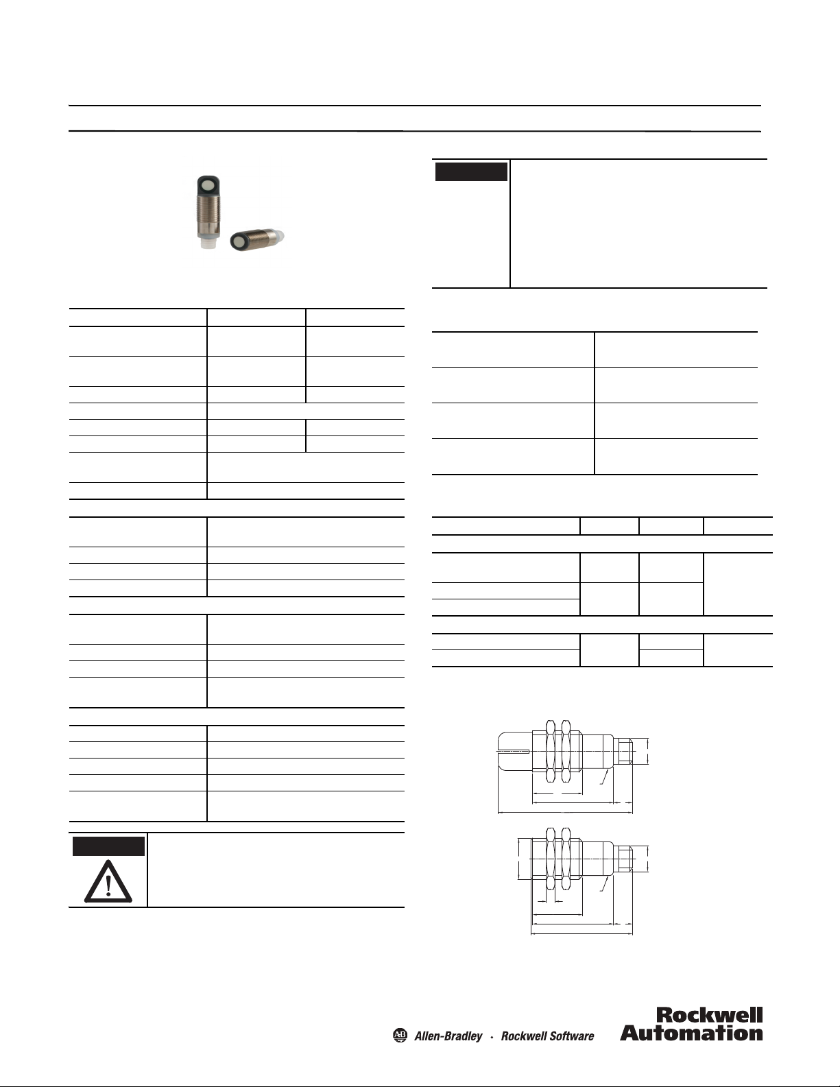
Dimensions [mm (in.)]
Right Angle Model
M12X1
LED
24.5
(0.96)
39.2 (1.54)
67 (26.6)
10
(0.39)
Straight Model
4
(0.16)
24.5 (0.96)
39.2 (1.54)
67.7 (2.66)
LED
10
(0.39)
M12X1M18X1
Page 2
Power, Control and Information Solutions Headquarters
Americas: Rockwell Automation, 1201 South Second Street, Milwaukee, WI 53204-2496 USA, Tel: (1) 414.382.2000, Fax: (1) 414.382.4444
Europe/Middle East/Africa: Rockwell Automation NV, Pegasus Park, De Kleetlaan 12a, 1831 Diegem, Belgium, Tel: (32) 2 663 0600, Fax: (32) 2 663 0640
Asia Pacic: Rockwell Automation, Level 14, Core F, Cyberport 3, 100 Cyberport Road, Hong Kong, Tel: (852) 2887 4788, Fax: (852) 2508 1846
www.rockwel lautomation.com
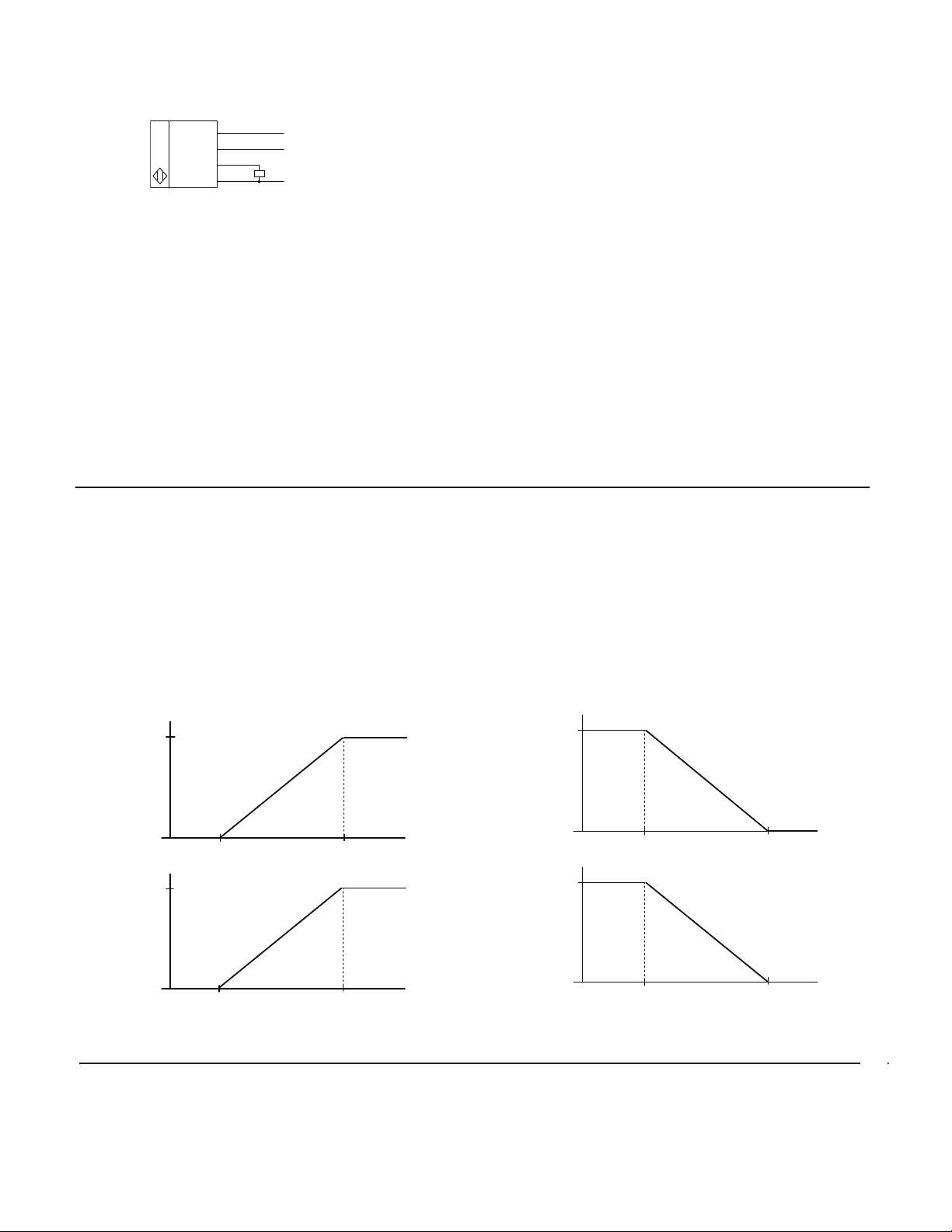
Wiring Diagram
Target Position
4
20
Set point P2Set point P1
Analog Current (mA)
Target Position
0
10
Set point P2Set point P1
Analog Voltage (V DC)
Target Position
4
20
Set point P1Set point P2
Analog Current (mA)
Target Position
0
10
Set point P1Set point P2
Analog Voltage (V DC)
1 (Brown)
2 (White)
4 (Black)
3 (Blue)
* Analog Voltage models are 15…30V DC
+10…30V DC *
Remote teach
Analog output by cat. no.
0V DC
Analog Output Characteristics
• The analog output mode returns a 4…20 mA or 0…10V DC
signal proportional to the measured value.
• The upper and lower adjustment range can be scaled to
distance-fixed window, giving the user more flexibility.
• The sensor is taught using an easy four-step remote teach
process or an optional programming cord.
• Two output functions: rising ramp and falling ramp.
Overview of Sensing and Adjustment Ranges
• When the target is beyond the far limit, or if target is absent,
the output is identical to the status at the far limit.
Setting Measurement Range
Rising Ramp: current or voltage values rise as the distance from
the target to the sensor increases.
Follow the steps below in the order they appear.
1. Place the target at the lower set point limit.
2. Using the white wire, connect to 0V DC [–] or press A1 on the
optional programming cable.
3. Place the target at the upper set limit.
4. Using the white wire, connect to 10…30V DC [+] or press A2 on
the optional programming cable
For example, if the span window is set to 4 mA at 7.62 mm (3
in.), and 20 mA at 203.2 mm (8 in.), the output will be 20 mA
when the target is anywhere at or beyond 203.2 mm (8 in.), or if
no target is present.
•In the blind zone, the output status is unpredictable because
the sensor does not have time to settle after the pulse. It is
therefore unable to accurately “hear” or interpret an echo.
•The adjustment range is where programming limits can be
stored; the sensing range is where stable sensing is possible
(see “Specifications”).
• The following example for a 300 mm sensor demonstrates the
need for both adjustment and sensing ranges:
If the blind zone were 0…30 mm, and you set a sensing
window of 50…300 mm, the output would become random/
unpredictable if the target object moved even slightly closer to
the sensor than 30 mm.
By defining the sensing range (usable but non-adjustable area
between 30 mm and 50 mm), the output is guaranteed to be
stable if the target mistakenly moves closer than the 50 mm
adjustable limit. Once the target moves into the blind zone
(closer than 30 mm) the output status becomes random/
unpredictable.
Falling Ramp: current or voltage values fall as the distance from
the target to the sensor increases.
Follow the steps below in the order they appear.
1. Place the target at the lower set point limit.
2. Using the white wire, connect to 10…30V DC [+] or press A2 on
the optional programming cable.
3. Place the target at the upper set limit.
4. Using the white wire, connect to 0V DC [–] or press A1 on the
optional programming cable.
10000231110 Ver 03
873M-IN001A-EN-P
June 2013
 Loading...