

Page 1
Installation Instructions
Sensor
Operating Voltage
10.8-30V DC
/
MAR/
873E RightSoundt Ultrasonic Opposed Mode Sensors
S Continuously adjustable emitter amplitude with instability
indicator allows for simple optimized adjustment over 2
inch to 30 inch sensing range.
S Ideal solution for sensing clear objects or materials
including glass and plastic bottles.
S Highly immune to ambient sonic and electrical noise.
S Popular right angle package allows through hole mounting
as well as 18mm threaded mounting hubs on the sensor
nose and base.
S Highly visible 360
top of the sensor.
S Designed to Rugged Food Industry Standards: enclosure
rated for 1200psi washdown as well as NEMA 4X, 6P and
IP67 water ingress standards.
S Receivers come with both NPN (sinking) and PNP
(sourcing) outputs; output logic switchable via polarity of
receiver power wiring; simplified product selection…
Select a 6.5 foot cable or a 6 inch pigtail quick-disconnect
and cordset and you’re ready to start sensing!
S 10.8–30V DC operation with protections for short circuit,
overload, reverse polarity, false pulse and transient noise
Description
RightSound Bulletin 873E sensors are opposed mode
ultrasonic sensors consisting of an emitter and a receiver.
The receiver is microprocessor based to provide advanced
temperature stability and noise immunity. A red instability
indicator LED is used to signal the operator when an
unreliable sensing condition is present due to low or high
emitter sound levels or of adverse environmental conditions.
Green power LEDs indicate power status to the emitter and
receiver. A yellow output energized LED indicates when the
receiver output is on. Precise tuning of the receiver to the
emitter minimizes interference from ambient noise sources.
A major advantage of the RightSound sensor is the emitter
volume control. The emitter volume control allows the
operator to correctly adjust the volume for the sensing
distance (distance from the emitter to the receiver) and other
variables of a given application (i.e., target speed and
spacing, etc.). For further details on this subject, please refer
to page 4 of this document, Application Information.
The sensing of clear objects, which can be difficult to do
reliably with photoelectric controls, is made highly reliable
with RightSound ultrasonic sensors. RightSound sensors
have been designed for demanding environments, especially
those of the Food and Beverage Industry. The NORYL
housings are extremely rugged and are rated for 1200psi
washdown and NEMA 4X and 6P standards. The acoustic
faces of the emitter and receiver are made of FDA compliant
silicone rubber for maximum durability and water ingress
protection.
RightSounds require 10.8V DC to 30V DC power. Receivers
come with both NPN current sinking and PNP current
sourcing outputs. Both outputs are rated 100mA. The receiver
has the ability to operate in either a normally open or normally
closed mode. The modes are selected by the polarity of
receiver supply voltage (see Wiring Diagrams on page 2).
When the receiver is in the normally open mode, the output
conducts when the receiver hears a RightSound emitter.
_
indicators conveniently mounted at the
When the receiver is in the normally closed mode, the output
conducts when the sonic beam from the emitter is blocked or
not present.
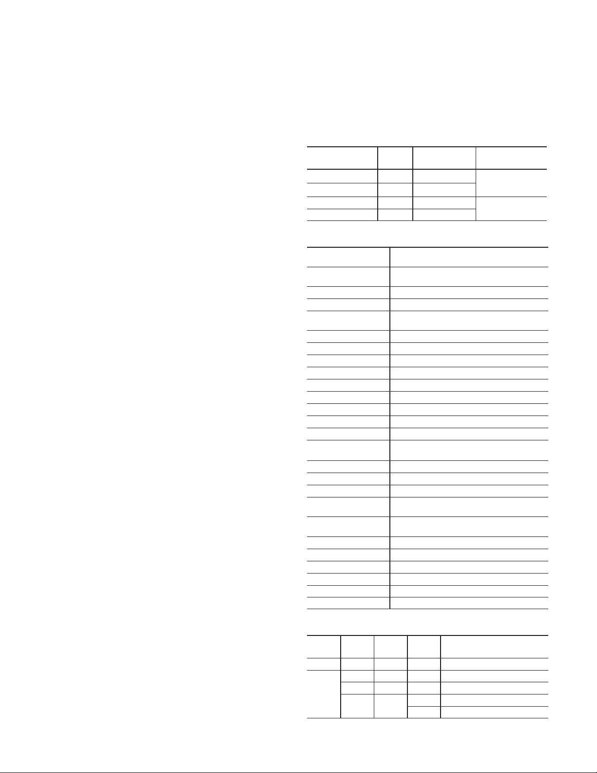
Selection Guide
Sensor Operating Voltage
Bulletin Number
873E-EDZZ0750A2 Emitter 2m (6.5ft) Cable 300V 10.8-30V DC
873E-EDZZ0750F4 Emitter Micro Style QD
873E-RDTT0750A2 Receiver 2m (6.5ft) Cable 300V
873E-RDTT0750F4 Receiver Micro Style QD
Type
Termination
Supply Current
20mA @ 20_C
100mA @ -25_C
10.8-30V DC
10mA
Specifications
Emitter 873E-EDZZ0750A2 (2m (6.5ft) 300V cable)
873E-EDZZ0750F4 (4Ćpin DC micro style QD pigtail)
Receiver 873E-RDTT0750A2 (2m (6.5ft) 300V cable)
Sensing Mode Opposed
Sensing Range 50mm to 750mm (2in to 30in)
Unit Protection False Pulse, Transient Noise, Short Circuit, Overload,
Operating Voltage 10.8-30V DC
Output Type NPN/PNP
Output Mode Normally Open/Normally Closed
Load Current 100mA max.
Leakage Current 0.1mA max.
Response Time <2.5ms
PowerĆup Delay <300ms
Max. Switching Frequency 125Hz
Ultrasonic Frequency 200-240kHz
Ultrasonic Pulse Cone
Housing Material Noryl
Sensing Face Material FDA compliant silicone rubber
LED Indicators See table below
Operating Environment NEMA 4X, 6P, IP67 (IEC529); 1200psi (8270kPa)
Connection Cable: #22 AWG PVC, 2m (6.5ft)
Vibration 20G, 10-55Hz (nonĆoperational)
Operating Temperature
Storage Temperature
Operating Humidity Not to exceed 95%, noncondensing
Approvals UL, c-UL, and CE marked for all applicable directives
Standards IEC 60947-5-2, EN60947-5-2
873E-RDTT0750F4 (4Ćpin DC micro style QD pigtail)
Reverse Polarity
(+/-) 5_
Angle
washdown
QD: 4Ćpin DC micro style male receptacle on pigtail
-25_C to +70_C (-13_F to +158_F)
-40_C to +85_C (-40_F to +185_F)
LED Indicator Lights
Sensor
Type
Emitter Ċ Green On Sensor powered
Receiver
Label Color State Status
PWR Green On Sensor powered
OUT Yellow On Output is conducting
MAR
SCP
Red
On Unreliable sensing condition
Flashing Output in overload or short circuit
Page 2
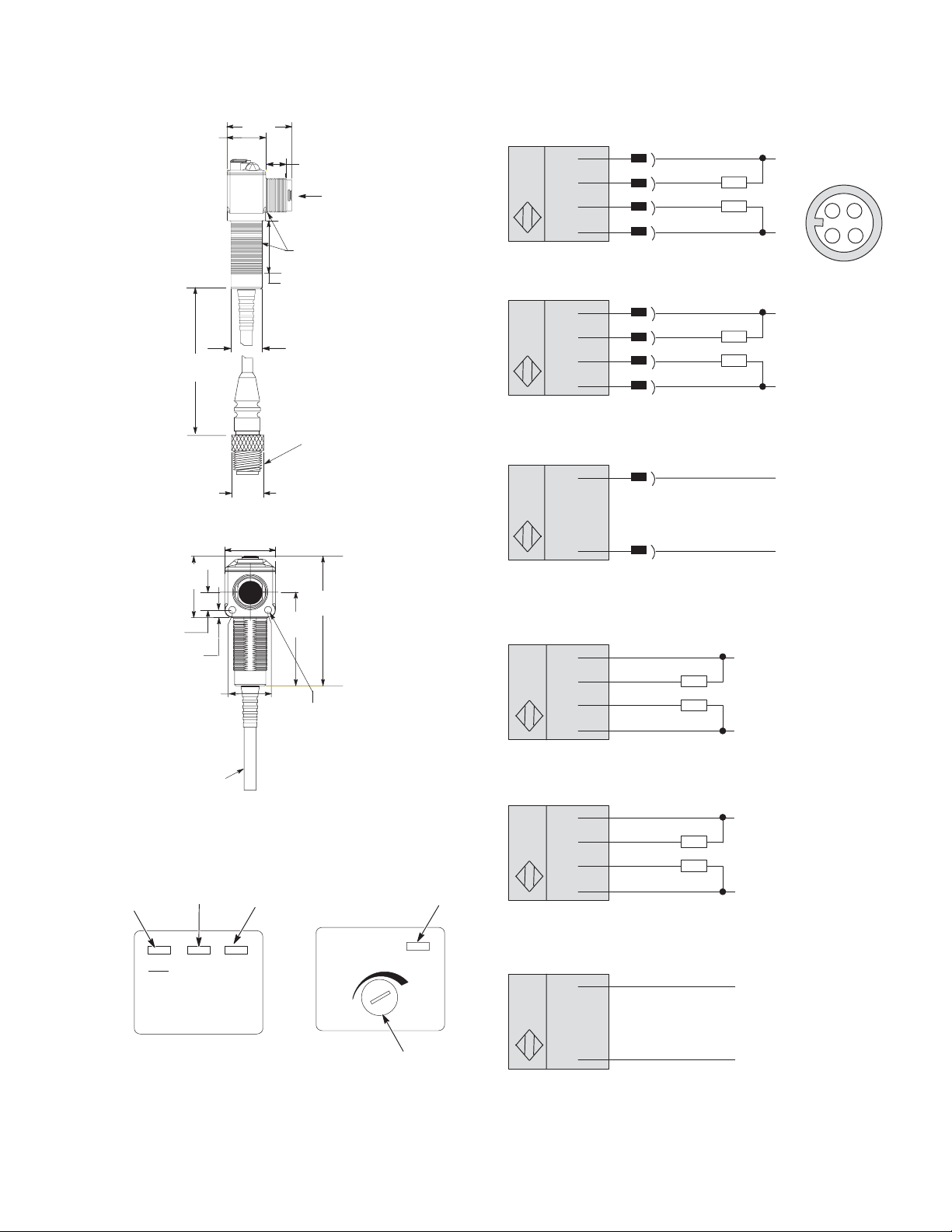
Dimensions—mm (in)
20.5
(0.81)
152/165
(6.0/6.5)
32.7
(1.29)
9.6
(0.38)
4
(0.16)
19
(0.75)
2m (6.56ft)
cable
LED and Adjustment Locations
RightSound Ultrasonic
Receiver
Red LED
Stability/Protection
Yellow LED
Output
35.1
(1.38)
(0.40)
M18 X 1.0
Thread
26.5
(1.04)
16.5
(0.65)
Micro
QuickĆDisconnect
14.48
(0.57)
27
(1.06)
49.7
(1.96)
3.6 (0.145) dia.
Clearance for #6-32 Screw
(2 places)
Green LED
Power
10
Emitter/Receiver
Face
69
(2.72)
RightSound Ultrasonic
Emitter
Green LED
Power
Wiring Diagrams
Receivers with Quick-Disconnect
Normally Open Configuration
1
Brown
2
White (NPN)
4
Black (PNP)
3
Blue
QuickĆDisconnect
Normally Closed Configuration
3
Blue
2
White (NPN)
4
Black (PNP)
1
Brown
QuickĆDisconnect
Emitter with Quick-Disconnect
Brown
1
Blue
3
QuickĆDisconnect
Receivers with Cable
Normally Open Configuration
Brown
White (NPN)
Black (PNP)
Blue
Cable
Normally Closed Configuration
Blue
White (NPN)
Black (PNP)
Brown
Cable
+10.8-30V DC
1324
-
+10.8-30V DC
-
+10.8-30V DC
-
+10.8-30V DC
-
+10.8-30V DC
-
MAR
SCP
PWROUT
1 Turn Knob
Vol ume
Brown
Blue
+10.8-30V DC
-
Cable
2
Emitter with Cable
Page 3

Specifications
1 Brown
34
3A
Coupling Nut NickelĆPlated Brass
Connector Molded oilĆresistant polyurethane body
Contacts Gold over nickelĆplated brass
Cable OilĆresistant PVC jacket, 22AWG conductors, 300V, UL recognized and
Cable O.D. 4/c = 5mm (0.21in)
Temperature
CSA certified
5/c = 6.5mm (0.25in)
-20_C to +105_C (-4_F to +221_F)
Features
Dimensions—mm (in)
Dimensions are approximate.
Illustrations are not drawn to scale.
42
(1.7)
Straight Female
S UL recognized and CSA certified
S Ratcheting coupling nut (on 4-pin DC cordsets)
S Highly visible yellow PVC jacket offers good oil and
chemical resistance
Selection Guide
Female Connector (Sensor End) Cable
Face View of Female Connector Style Wire Color Wire Rating LengthĊm (ft)
2 (6.5) 889D-F4AC-2
12
34
Straight
2 White
3 Blue
4 Black
22AWG
300V
5 (16.4) 889D-F4AC-5
10 (32.8) 889D-F4AC-10
15
(0.57)
Catalog Number
3
Page 4

Application Information
Operating Distance Selection
Operating distance is defined as the distance from the emitter
face to the receiver face. The maximum operating distance is
based on installing the control in a clean environment. Normal
industrial environments actually range from moderately dusty
to extremely dirty. In these environments, greater sensor
response may be required which can be obtained by reducing
the operating distance of the control or by increasing the
volume adjustment of the emitter (turn clockwise).
Application Precautions
With very small separation between the emitter and the
receiver, it may be necessary to misalign the receiver by
about 5_ off axis to reduce the effect of reflections.
The product may not function correctly if mounted too close to
high energy ultrasonic sources (such as ultrasonic welders or
cleaners). If such sources are present, set a blocking target
so that the red margin indicator just turns off and then activate
the welder or cleaner. If the margin indicator turns on or
flashes, greater physical separation between the sensors and
the noise source is required.
CAUTION: Care should be taken to
prevent applying force to the
emitter/receiver face. This can
damage the sensor.
Adjacent Pairs of Emitters/Receivers
When emitter/receiver pairs are used in close proximity,
precautions must be taken to prevent crosstalk (the response
of a receiver to the wrong emitter). Emitters should always be
pointed in the same direction so that the sonic beams are
parallel to each other.
A minimum spacing of 5cm (2in) must be maintained between
adjacent pairs for emitter-receiver separations of up to 15cm
(6in). Add 1cm (0.4in) of adjacent pair spacing for every
additional 10cm (4in) of emitter-receiver separation beyond
15cm (6in).
Alignment
1. Connect load(s) to the receiver.
2. Apply 10.8–30V DC power to the emitter and receiver.
The GREEN indicator must turn ON on both emitter and
receiver.
3. Position the receiver sensing face opposite the emitter
sensing face, with a separation of no more than 30I.
Center the acoustic beam by aligning the emitter and
receiver on the same axis.
4. If the RED indicator is ON, adjust the transmitter
SENSITIVITY until the RED indicator light turns OFF.
5. Breaking the acoustic beam with a target object will now
cause the output to switch, as indicated by the YELLOW
indicator.
In certain applications, the sensing target will break the center
of the acoustic beam, halfway between the transmitter and
receiver controls. With smaller sensing targets (a surface less
than 1/2I wide), it may be necessary to position the
transmitter and receiver controls so that the target breaks the
acoustic beam closer to the face of the transmitter or receiver.
If the sensing target is large (a surface wider than 1I), greater
noise immunity may be obtained by increasing the sensitivity
setting further, but not to the point where the RED indicator
lights when the target is present.
In general, operation with the RED indicator illuminated either
when the target is present or absent should be avoided by
adjusting the sensitivity setting smaller (counterclockwise) if
the RED indicator illuminates when the target is present or
greater (clockwise) if the RED indicator illuminates when the
target is absent.
Warranty
Rockwell Automation/Allen-Bradley does not supply warranty
information with documentation that ships with products.
Warranty information can be found in the Sensors catalog in
the “General” section. This can be reached via the Internet at
www.ab.com/catalogs.
Installation
The controls should also be set up away from sources of
powerful airflow (such as fans or blowers) and away from
powerful direct heat sources (such as space heaters or open
ovens).
The control must be securely mounted on a firm, stable
surface or support. A mounting which is subject to excessive
vibration or shifting may cause intermittent operation.
Wiring
All external wiring should conform to the National Electrical
Code and applicable local codes. See wiring diagrams for
external connections.
Publication 75009–119–01(C)
June 2001
4
 Loading...