

Page 1
Installation Instructions
)
Bulletin 873C Ultrasonic Proximity Sensor
IMPORTANT: SAVE THESE INSTRUCTIONS FOR FUTURE USE.
CAUTION: Solid-state devices can be susceptible to radio frequency (RF) interference depending on the power and
!
WARNING: If a hazardous condition can result from unintended operation of this device, access to the sensing area
!
the frequency of the transmitting source. If RF transmitting equipment is to be used in the vicinity of the
solid state devices, thorough testing should be performed to assure that transmitter operation is
restricted to a safe operating distance from the control equipment and its wiring.
should be guarded.
Specifications
Switching Output Analog Output
New Part Number 873C-DDNP1000E2 873C-DDAV1000E2
Old Part Number 873C-D30NP30-E2 873C-D30AP30-E2
Nominal Sensing Distance 30cm (11.8 in.) to 1m (39.4 in.)
Output Configuration N.O., PNP Analog, PNP
Operating Voltage 18-30V DC
Load Current
Minimum Load Current 1mA
Leakage Current
Voltage Drop
Repeatability
Hysteresis
Ultrasonic Frequency 200kHz
Max. Switching Frequency 5Hz
Ultrasonic Pulse Cone Angle
False Pulse Protection Incorporated
Transient Noise Protection Incorporated
Reverse Polarity Protection Incorporated
Short Circuit Protection Incorporated
Overload Protection Incorporated
Enclosure NEMA 12 and IP65 (IEC 529)
Connection Cable: 2Ćmeter (6.5 ft.) length
LED Output Energized
Operating Temperature
Shock and Vibration 30G, 10-55Hz
≤400mA ≤5mA
≤10µA
≤2.4V
±5mm in axial direction
≤15mm typical
8° (full angle)
NickelĆplated brass barrel
3Ćconductor PVC
-10°C to +60°C (-14°F to +140°F)
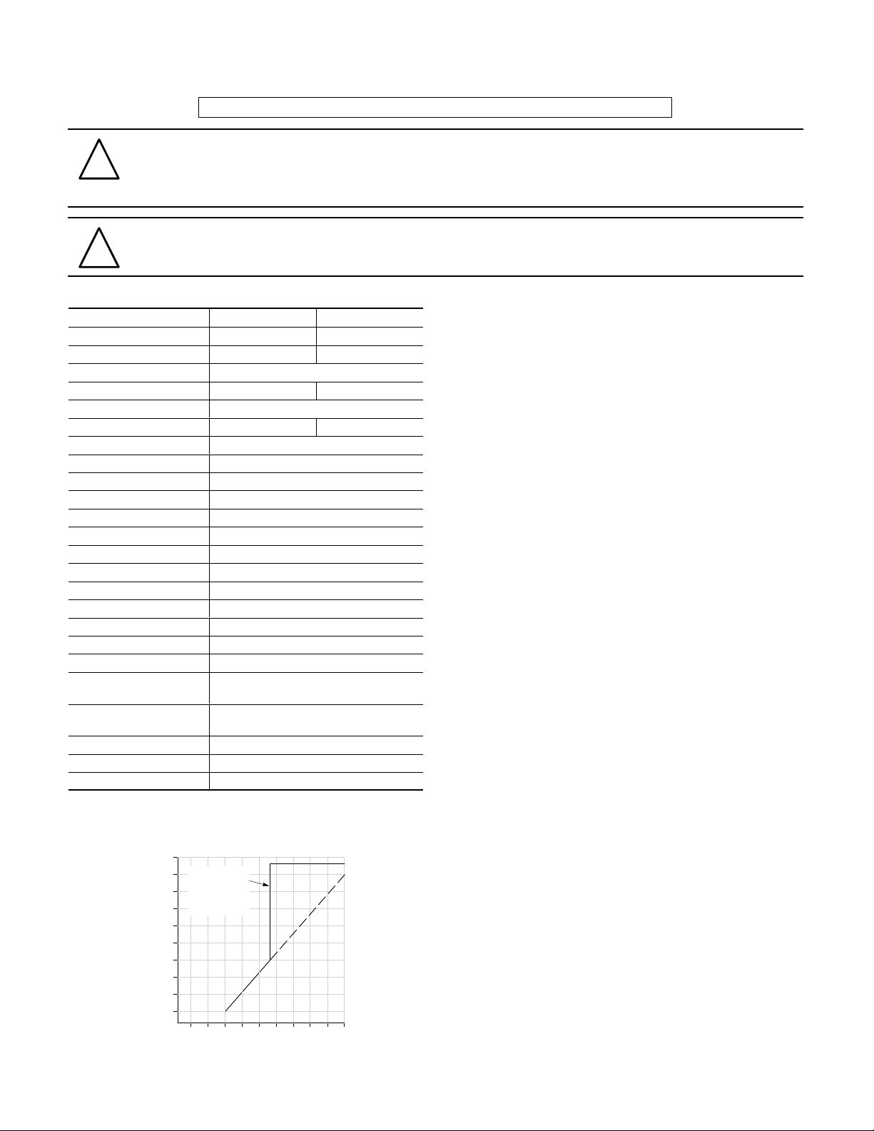
Analog Output Voltage vs. Target Distance
(Background Suppression at Maximum Distance)
10
Background
9
Suppression
Ouput Voltage (V DC)
8
7
6
5
4
3
2
1
Setpoint
(Adjustable)
0.1 0.2 0.3 0.4 0.5 0.6 0.7 0.8 0.9 1.0
Sensing Distance (meters
Description
Bulletin 873C ultrasonic sensors are solid-state devices
designed for noncontact sensing of solid and liquid objects.
The normally open switching (discrete) model features a long
sensing range which can be adjusted between 30cm (1 1.8in)
and 1m (3.3ft). All sound-reflecting objects that are within the
selected sensing range and more than 30cm from the sensor
face can be detected.
The analog model provides an output voltage that varies
linearly with target distance. For many applications, such as
monitoring the level of water in a tank or accurately positioning
a cardboard box, this technology allows a single device to do
a job that would otherwise require multiple sensors.
Each unit is housed by a plastic face and a nickel-plated brass
barrel which meet NEMA 12 and IP65 (IEC 529) enclosure
standards. It is equipped with a 2m (6.6ft) PVC cable and an
LED which glows when a target is detected.
Theory of Operation
Ultrasonic sensors emit bursts of high-frequency sound waves
which reflect or “echo” from a target. When the device detects
an echo, it energizes the load. This allows these sensors to
detect an object of any shape and material that can sufficiently
reflect an ultrasonic pulse.
Each switch senses the distance from its face to the target by
measuring the length of time required for the echo to return.
The analog model converts the time value to a DC output
voltage. The discrete model compares this time to a pre-set
value (set by the user at installation) and energizes the load
when the time drops below the threshold.
Sensing Distance
The 873C is designed to detect objects which are between
30cm (1 1.8in) and 1m (39.4in) from the sensor face. The
discrete switching model’s maximum sensing distance can be
adjusted within this range by turning the potentiometer on the
end of the sensor.
Any objects in front of the sensor must be at least 30cm from
the detector face. Objects closer than 30cm will not be
detected and will block the sound waves coming from the
sensor.
Page 2
Background Suppression and Non-Target Objects
The analog model offers a background suppression feature
which allows the sensor to ignore all objects beyond a
specified distance. This distance is set by the user at
installation by turning the potentiometer on the end of the
sensor.
Non-target objects in the sensing field can be “hidden” from
the sensor by covering them with sound-absorbent material or
by positioning them so that their echoes are reflected away
from the sensor.
Target Considerations
Because ultrasonic sensors depend on a reflected sound
wave for proper operation, the shape, material, temperature
and positioning of the target are important. These must be
selected to return the strongest echo, otherwise the sensing
distance will be reduced or the target will not be detected.
The ideal target shape is a smooth, flat surface. Rounded or
uneven objects can also be detected, but the sensing
distances and/or analog output voltages may be reduced.
An object must be close to the sensor barrel axis to be
detected because the 873C emits ultrasonic pulses in an 8_
cone. Targets must be within this cone to reflect the pulses
and activate the switch. The object’s surface must also face
directly toward the sensor to give a proper echo.
Material thinner than 0.01mm (0.0004in) and soft materials
such as fabric or foam rubber are difficult to detect by
ultrasonic technology because they are not adequately
sound-reflective.
Target temperatures must be at or below 100° C (212° F) for
reliable sensing. Targets at higher temperatures create
convection currents in the air near their surfaces, which
disturbs the reflection of the ultrasonic pulse.
Mounting Considerations
The control must be securely mounted on a firm, stable
surface or support. A mounting configuration which is unstable
or subject to excessive vibration may cause intermittent
operation.
An 873C sensor can be mounted with its sensing face flush to
surrounding surfaces. This does not effect sensing distance.
A mounting location should be chosen such that the target’s
surface faces directly toward the sensor.
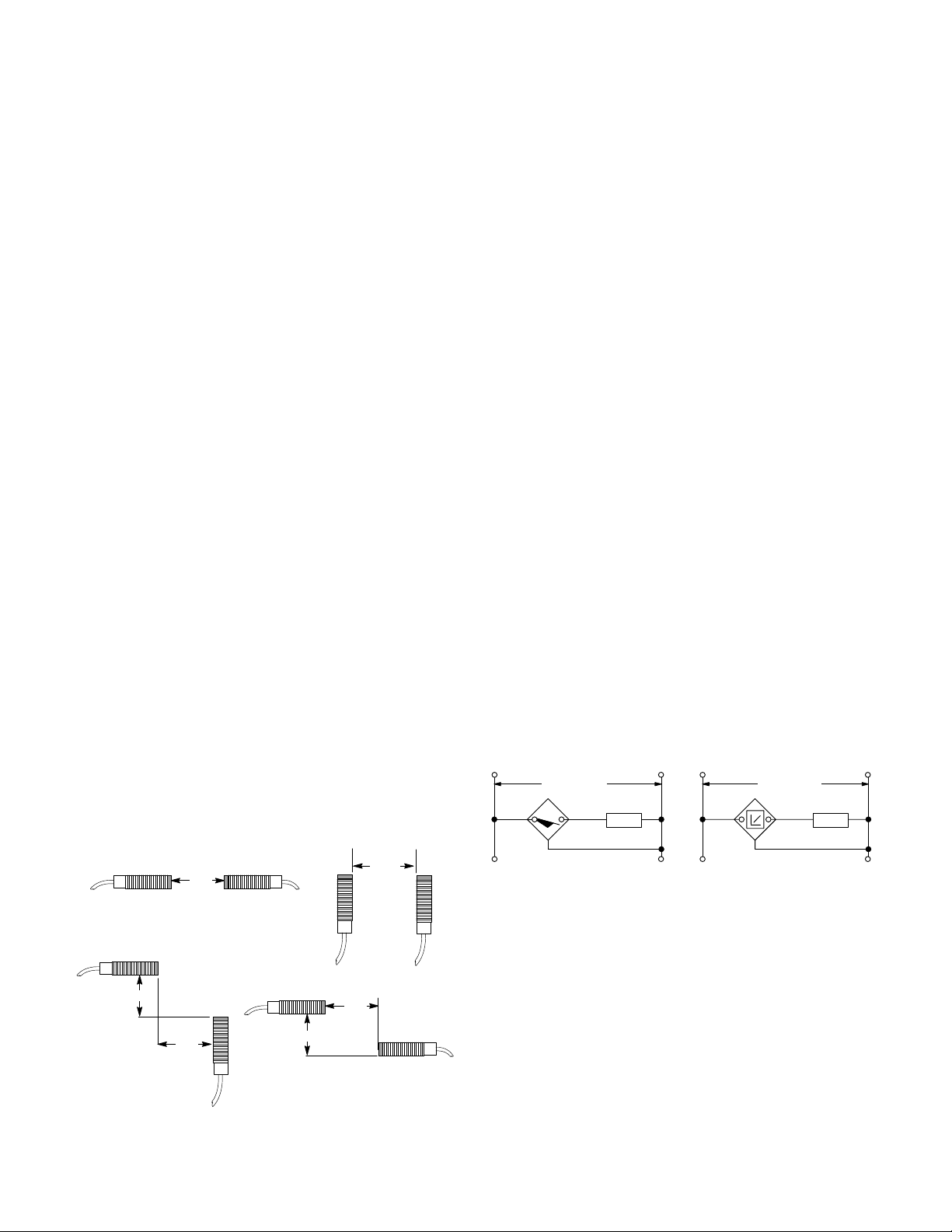
When more than one 873C is in use, the following inter-sensor
spacings must be maintained:
1.5m
6m
Environmental Factors
The output of these devices drifts approximately 0.2% per
degree Celsius of temperature change. The analog model
output voltage drops slightly as the temperature increases,
even if the target has not moved. The sensing distance of the
discrete switching model rises with increased temperature.
Strong air turbulence and convection currents can interfere
with operation of the sensor. Installation of baf fles around the
sound cone can help to reduce these effects.
Liquid splashes or heavy condensation on the face of the
sensor can interfere with proper operation. In liquid
applications, the device could be protected by relaying the
ultrasonic pulse to the surface of the liquid via a flat “bounce
panel.” Installing shielding around the sensor can also help to
reduce splash and condensation interference.
873C ultrasonic sensors are not effected by humidity, dust,
mist, or changes in atmospheric pressure.
Wiring
All external wiring should conform to the National Electric
Code and applicable local codes. Connect the proximity
switch to the power supply and load as shown in the wiring
diagrams and as described below.
1. Connect the BROWN wire from the proximity control to the
positive (+) side of the 18–30V DC supply.
2. Connect the BLUE wire from the proximity control to the
negative (–) side of the 18–30V DC supply .
3. Connect the BLACK wire from the proximity control to the
positive input of the load.
NOTE: If the positive (+) and negative (–) wires are reversed,
the switch will not operate properly . The sensor will not be
damaged because it is equipped with reverse polarity
protection.
NOTE: These switches are equipped with protection against
transient noise. However, it is recommended that the proximity
cable not be placed in the same conduit as AC power wiring.
Normally Open Switching
+ –
PNP (Sourcing)
Brn
18–30V DC
Blk
Blue
Load
–+
+ –
Analog
PNP (Sourcing)
Brn
18–30V DC
Blk
Load
Blue
–+
Wiring Switches in Series and Parallel
Series and parallel connection of this product is not
recommended.
2m
2m
3m
2m
Page 3

Alignment
The sensor can be positioned accurately using the LED on its
end, which glows with an intensity proportional to the strength
of the echo. Align the device as described below:
1. Place the target in the desired sensing position.
2. Choose a sensor location such that the surface of the
target faces directly toward the sensor. The distance
between the target and the switch must be between 30cm
(1 1.8in) and 1m (39.4in).
3. Mount the sensor on a firm, stable surface or support.
4. Apply power to the sensor as described above.
5. Turn the potentiometer on the end of the sensor fully
clockwise. This will disable the analog model background
suppression or set the discrete switching model sensing
distance to maximum. Check that the LED turns on.
6. Adjust the angle of the sensor to maximize the brightness
of the LED.
7. (Analog model only) If the analog model is sensing objects
behind the desired target, turn the potentiometer on the
end of the sensor counter-clockwise to suppress the
background objects, but not so far that the sensor no
longer detects the target.
8. (Discrete switching model only) Adjust the potentiometer
on the discrete switching model counter-clockwise until the
LED turn off, then slowly clockwise until the LED turns
back on. The sensing distance is now set at the target
location.
Dimensions—mm (inches)
LED
Adjustment Potentiometer
30.0
(1.18)
12.0
(0.47)
95.0
(3.74)
117.0
(4.61)
Accessories
Description Part Number
Mounting Brackets
Right Angle 871A-BRN30
Clamp 871A-BP30
Tilt Swivel 60-2439
Conduit adaptors 871C-N31
Page 4

Publication 46803–053–01(B)
March 1999
Printed in USA
 Loading...