

Page 1

Installation Instructions
8720SM High Performance AC Induction
Motors
(Catalog Number 8720S M-xxxxxxxSx)
Introduction
This publication provide s installation instructi ons for the 8720SM
motors. Use this document if you are responsible for the design
and installation of 8720SM motors. Refer to the 8720MC High
Performance Drive Integration Manual (publication
8720MC-IN002x-EN-P) for performance information.
For: See page:
Complying w ith European Unio n Directives 2
8720SM AC Motor Overview 3
8720SM Receiving and Storage Information 4
Before Mounting Your Motor 5
Building Your 8720SM Motor Cables 7
Guidelines for Installing Your Motor 8
Wiring Your 8720SM Motor Power 9
Blower Motor 13
Motor Operation and Maintenance 15
Specifications 16
Dimensions 18
Motor Load Force Ratings 25
Publication 8720SM-IN001A-EN-P — February 2003
Page 2

2 8720SM High Perform a n ce AC Induction Motors
Complying with European Union Directives
If this product is installed wi t hi n the Eu rope an Uni on or EEC reg io ns
and has the CE mark, the following re g ul a ti ons apply.
EMC Directive
This unit is tested to meet Council Directive 89/336/EEC
Electromagnetic Compatib ility (EMC) using the f ollowing s tandards, i n
whole or in part:
•
EN 50081-2 EMC - Emission Standard, Part 2 - Industrial
Environment
•
EN 50082-2 EMC - Immunity Standard, Part 2 - Industrial
Environment
•
EN 61800-3 - Adjustable Speed Electrical Power Drive Systems,
Part 3 - EMC Product Standard inclu ding specific test methods
The product described in thi s installation instructions is intended fo r
use in an industrial environment.
Low Voltage Directive
These units are tested to meet Council Directi ve 73/2 3/EEC Low
Voltage Directive. The EN 60204-1 Safety of Machinery-Electrical
Equipment of Machines, Part 1-Specification for General Requirements
standard applies in whol e or in part.
Publication 8720SM-IN001A-EN-P — February 2003
Page 3
8720SM High Performance AC Induction Motors 3
8720SM AC Motor Overview
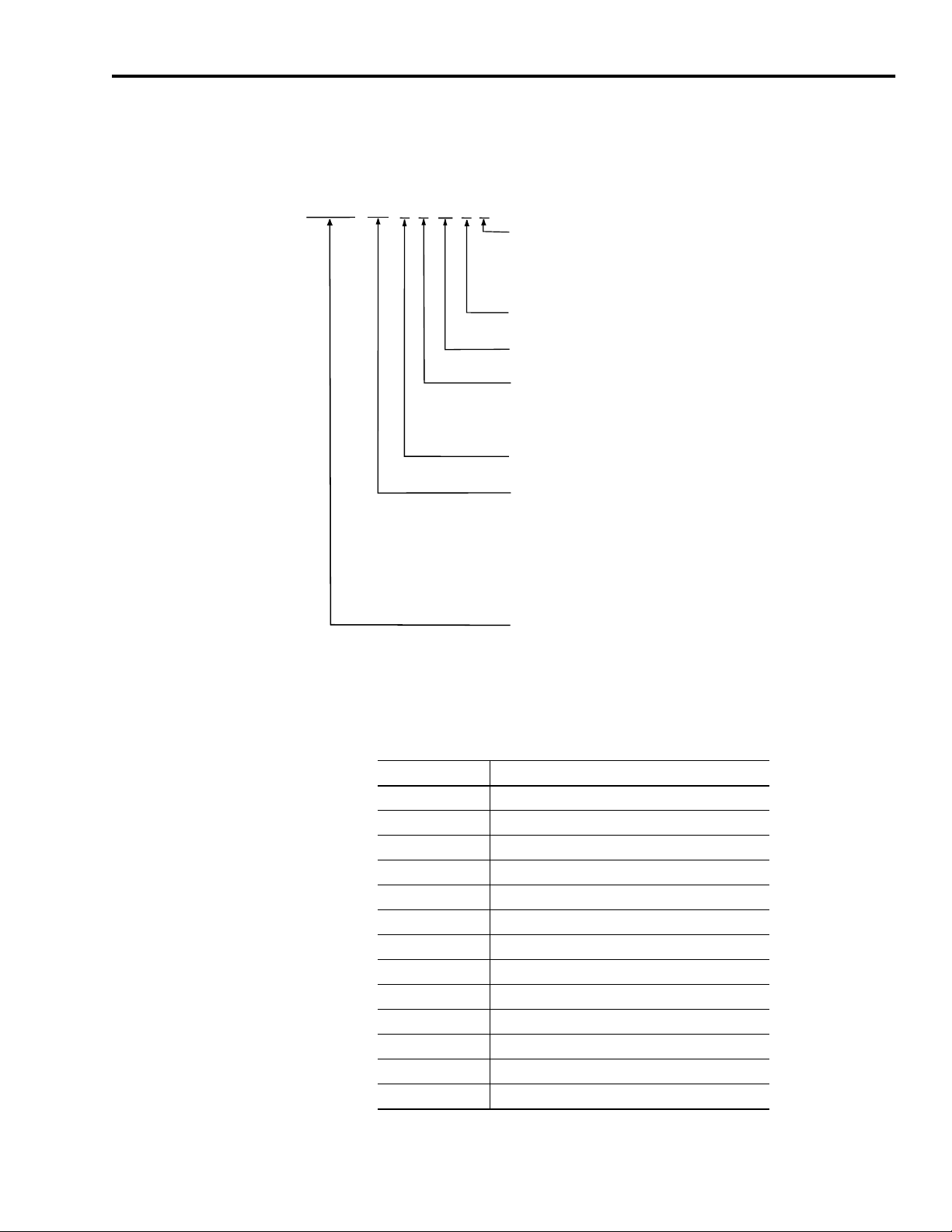
8720SM -
The 8720SM motors are high performance AC induction motors
specifically designed for use with the Allen-Bradley 8720MC Drives.
Refer to the configurator below to help identify your 8720SM motor.
xxx
x x xx S x
Feedback1
1 = SRS-660 (high resolution incremental feedback, MP-Series connector)
2 = SRM-60 (high resolution absolute feedback, MP-Series connector)
3 = SNS-60 (incremental feedback with marker)
4 = SNS-60 (incremental feedback with marker, MP-Series connector)
Speed Class
S = Standard
Curve Identification
Refer to publication 8720MC-IN002
Frame Number
1 = 112
2 = 132
3 = 132A
Winding Type
S = Single
Power
005 = 5.5 kW
007 = 7.5 kW
011 = 11 kW
015 = 15 kW
018 = 18.5 kW
022 = 22 kW
030 = 30 kW
Bulletin Number
4 = 160
5 = 180
6 = 200
037 = 37 kW
045 = 45 kW
055 = 55 kW
063 = 63 kW
075 = 75 kW
093 = 93 kW
x
-EN-P
1
Feedback options 1 and 2 apply to SERCOS mode applications. Feedback options 3 and 4 apply to Analog mode
applications.
Refer to the following table to compare the motor frame number to
the motor catalog number.
Frame Catalog Number (8720SM)
DL1106 -005S1BASx, -005 S1BBSx, -005S1BCSx
DL1108 -007S1CASx, -007 S1CBSx, -007S1CCSx
DL1110 -011S1DASx, -011S1DBSx, -011S1DCSx
RDL1307 -015S2EASx, -015S2EBSx, -015S2ECSx
RDL1308 -018S2FASx, -018S2FBSx
RDL1310 -022S2GASx
RDL1611 -030S4JASx
RDL1613 -037S4KASx
DL1811 -045S5NASx
DL1813 -055S5PASx
DL1815 -063S5QASx
DL2010 -075S6SASx
DL2012 -093S6TASx
Publication 8720SM-IN001A-EN-P — February 2003
Page 4
4 8720SM High Perform a n ce AC Induction Motors
8720SM Receiving and Storage Information
The customer is responsible for inspecting the equipment before
accepting the shipme nt from the freight company. Check t he items
against your purchase order.
Handling
The 8720SM motors are equipped with lifting eye bolts. These eye
bolts are provided to assist in handling and mounting the motors. The
motors can accommodate either flange or foot mount.
ATTENTION
Eyebolts may unscrew during lifting. Check the
eyebolts to insure that they are tight. Failure to
observe this precaution could result in bodily injury.
!
Storage
Store motors in a clean, dry area protected from extreme
temperatures, moisture, shock, and vibration. Observe storage
temperatures of -20° to 80° C (-4° to 176° F) with a relative humidity
of 5 to 95%.
IMPORTANT
ATTENTION
!
The application of motors and other electrical equipment in hazardous
locations is restricted by the National Electric Code. To ensure
compliance, observe these regulations and consult with local code
inspection and enforcement agencies.
All drains are fully operable while in storage. Store
motors so that the drain is at the lowest point. Dr ains
are located in the lower po rtion of the motor c astings
on both the drive and non-drive ends of the motor.
Only qualified electrical personnel familiar with the
construction and operation of this equipment and the
hazards involved should in st al l, adjust, operate, and/
or service this equipment. Read and un de rstand this
document in its entirety before proceeding. Failure to
observe this precaution could result in severe bodily
injury or loss of life.
Publication 8720SM-IN001A-EN-P — February 2003
Page 5
8720SM High Performance AC Induction Motors 5
Before Mounting Your Motor
Before mounting your 8720SM motor, consider the following:
•
You can mount the motor horizontally or v e r tically with t h e sh aft
down or up.
•
The 8720SM motors are blower cooled with air flow from the
blower end to the drive end. The air flow must be flowing in the
direction of the arrow on the motor to provide adequate cooling.
Both air inlets and outlets must be free of obstructions. Maintain a
clearance of at least 100 mm (4 in.) at the bl ower inlet area.
•
When mounted, the motor must not be exposed to direct splash
or spray of cutting fluids or lubricatin g oils.
•
Motors include a labyrinth type shaft seal with flinger, which helps
protects against splashing. However, it will not provide protection
against flooding.
•
In an environment where high humidity is present or the motor
blower inlet air is saturated with coolant mist, make sure the
motor is mounted with the feet down and the drain holes at the
bottom of the motor are open.
•
The motors are designed for the ambient temperature i ndicated on
the nameplate. The standard motor maximum ambient is 40° C
(104° F). Locate the motor where the ambient temperature
require m ents are sat isfied and wh ere clean air has fre e access to
ventilating intake an d outlet openings . Except for machines w ith a
suitable protective enclos ure , t he locat i on should be clean and
dry.
IMPORTANT
ATTENTION
!
The cooling system on standard 8 7 20S M bl owe r
cooled motors requires that clean air is forced
through ducts which are integral to the stator frame.
It is important that you keep these ai r passages clean
and that sufficient clearance is provided on the
motor air inlets and stator duct outlets for
unrestricted air flow.
Y ou must be careful to prevent debris (such as metal
shavings and conduit knockouts) from falling into
the motor while performing any installation work
around the motor. A hazard of personal injury and/or
equipment damage exists if foreign material lodges
inside the motor.
Publication 8720SM-IN001A-EN-P — February 2003
Page 6

6 8720SM High Perform a n ce AC Induction Motors
Using Belted Driv es and Coupled Drives
Proper alignment is key for long life of bearings, shafts and belts, and
minimum downtime.
Belted Drives
If you use motor slide bases or rails, you must securely anchor them
to the foundation with the proper bolts. Make sure the motor shaft
and load shaft are parallel, and that the sheaves are aligned.
When a motor is belt coupled, the belt tension must not exceed the
radial load capabilities of the motor beari ngs. For belt drives, place the
sheave as close as possible to the motor bracket. The maximum
allowable radial load is assumed to be applied at the end of the motor
drive shaft.
IMPORTANT
Do not exceed the maximum allowable radial load
on the end of the shaft. Refer to the Radial Load
Force Ratings (Zero Axial Load) on page 25 for a
listing of radial loads .
Coupled Drives
Use flexible couplings between the motor shaft and the load shaft.
Align the motor shaft and the load shaft to values recommended for
the specific coupling before coupling is connected.
IMPORTANT
Do not exceed the maximum allowab le axial load on
the end of the shaft. Refer to the Axial Load Force
Ratings (Zero Radial Load) on page 26 for a listing of
axial loads.
Balancing the Motor
Misalignment can cause excessive vibration and damaging forces to
the shaft and bearings. During high speed operation, a small
unbalance can cause significant vibration. Make sure to accurately
dynamically balance any gears, pulleys, or couplings that are mounted
to the motor shaft. Best results are obtained by balancing after the
device is mounted to the shaft.
Publication 8720SM-IN001A-EN-P — February 2003
Motors are dynamically balanced to stay wit hi n a vibration l imit of
0.12 in./s, measured in accordance with NEMA MG-12.06. Balance is
done with a full leng th 1/2 height shaft key. A full shaft key is s hipped
Page 7

8720SM High Performance AC Induction Motors 7
with the motor. Sheave or coupling should be balanced with a 1/2
height shaft key.
Preventing Electrical Noise
Use Electromagnetic Compatibility (EMC) techniques to reduce
Electromagnetic Interference (EMI), commonly called noise. Noise
adversely impacts motor performance by inducing stray signals.
Effective techniques to counter EMI include filtering the AC power,
shielding and separating signal carrying lines, and practicing good
grounding techniques.
To help avoid EMI:
•
Filter AC power by using isolated AC power transformers or
properly installed AC line filters.
•
Physically separate signal lines from motor cabling and power
wiring. Do not r oute signal wires with motor and power wir es, or
over the vent openings of servo drives.
Building Your 8720SM Motor Cables
•
Ground all equipment using a single-point parallel ground system
that employs ground bus bars or large straps.
Refer to System Design for Control of Electrical Noise Reference
Manual (GMC-RM001x-EN-P) for information on additional electrical
noise reduction techniques.
Proper cable construction and routing improves system
ElectroMagnetic Compatibili ty (EMC). Refer to the 8720MC High
Performance Drive Installation Manual (publication
8720MC-IN001x-EN-P) for information regarding cable const ruct i on.
Publication 8720SM-IN001A-EN-P — February 2003
Page 8
8 8720SM High Perform a n ce AC Induction Motors
Guidelines for Installing Your Motor
Observe the following for installing your motor:
ATTENTION
!
•
Allow sufficient clearance in the area of the motor for it to stay
within its specified ope r ating temperature as well as protected
from direct splash or spray of cutting fluids or lubricating oils.
Refer to Before Mounting Your Motor for additional information.
•
Refer to Using Belted Drives and Coupled Drives to determine
proper installation in r ega rd to using belted and coupled drive s .
•
Mount your motor on a rigid, solid base, or foundation. Poor base
construction may cause resonances i n the motor/base assembly,
which can result in bearing failure and other motor damage. Use
the correct grade of hold down bolt s for the type of mounting.
Refer to Specifications for recommended bolt torque values.
Only qualified electrical personnel familiar with the
construction and operation of this equipment and the
hazards involved should in st al l, adjust, operate, and/
or service this equipment. Failure to observe
precaution could result in severe bodily injury or loss
of life.
•
Determine that you hav e prop erl y cons truc ted ca bles availab le fo r
your application. Refer to the 8720MC High Performance Drive
Installation Manual (publication 8720MC-IN001x-EN-P) for
information regarding cable construction.
Publication 8720SM-IN001A-EN-P — February 2003
Page 9
8720SM High Performance AC Induction Motors 9
Wiring Your 8720SM Motor Power
The procedures in this section assume yo u have installed your 8720SM
motor correctly. This section includes:
•
determining conduit box orientati on
•
wiring your motor power
•
determining your feedback connections
•
verifying thermal protector (thermostat leads) connections
Determining Conduit Box Orientat ion
The standard conduit box location for to tally enclosed motors is top
mounted for left or right conduit entry without motor disassembly.
The 8720SM motors allow rotation of the conduit box in 90 degree
increments for lead outlet at front, back, or sides.
Wiring Your Motor Power
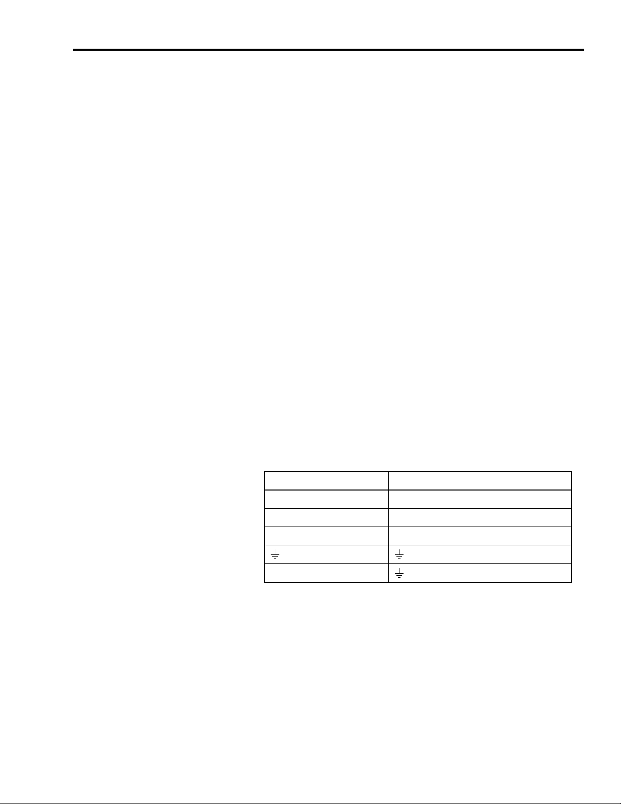
To wire your 8720SM three-phase motor power:
1. Bring 4 wire shiel de d Be ldon VFD cable or equal to these
connections. For applic ati ons above 130A, use thick insul a tion
lead wire such as RHW-2 or equal and thread the wires through a
single grounded metal conduit.
8720SM Motor: 8720MC Drive (TB1 terminal):
U (T1) U
V (T2) V
W (T3) W
Shield
Clamp
Publication 8720SM-IN001A-EN-P — February 2003
Page 10

10 8720SM High Performance AC Induction Motors
Figure 1
8720SM-005S1BASx Thru -093S6TASx Motors
Ground Bolt
U/T1
Rotatable Conduit Box
2. Connect the shield to both the motor ground and the PE ground
on the drive with an 6 mm
the 8720MC High Performance Drive Installation Manual
(publication 8720MC-IN001x-EN-P) for the PE ground terminal on
the 8720MC drive.
ATTENTION
!
Connect an appropriate equipment grounding
conductor to the 8720MC drive ground
terminal, the motor frame, the transformer
enclosure if used, the drive electrical enclosure,
and an appropriate grounding ele ctrode.
Failure to observe these precautions could
result in severe bodily injury or loss of life.
V/T2
W/T3
2
(AWG 10) or larger conductor . Refer to
Publication 8720SM-IN001A-EN-P — February 2003
Determining Your Feedback Connections
Refer to the following ta bl e to determine the motor/integ r a te d
feedback device combination.
Motor Encoder Type Control Type
8720SM-xxxxxxxS3 and -xxxxxxxS4 Incremental sine/cosine Analog
8720SM-xxxxxxxS1 Single-turn absolute feedback
SERCOS
8720SM-xxxxxxxS2 Multi-turn absolute feedback
These feedback devices provide precision servo performance for both
spindle and power servo applications. The mo tor feedback cable
(2090-CDNFDMP-Sxx) shown in Figure 2 applies to the
8720SM-xxxxxxxS1, S2, and S4 motor configurations.
Page 11

64
(2.5)
29.5
(1.16)
83.8
(3.3)
96.52
(3.8)
(0.38)
8720SM High Performance AC Induction Motors 11
Figure 2
Motor Feedback Cable (8720SM-xxxxxxxS1, S2, and S4)
Dimensions are in millimeters (inches)
9.65
A
B
N
C
P
V
D
R
S
E
F
G
Viewed from
Connector Face
M
L
U
K
T
J
H
26.9
(1.06)
2090-CDNFDMP-S
xx
The mating right-angle P-Lok feedback connector shown in Figure 3
applies to the 8720SM-xxxxxxxS3 motor (and ships with each motor).
This connector is designed for solder joints at each termination. The
Amphenol catalog number is P3106Z2029S23. Catalog number
ST-385-16S-08D pins are also provided.
Figure 3
Motor Feedback Connector (8720SM-xxxxxxxS3)
61.7
(2.43)
34.9
(1.4)
37.29
(1.47)
1.19-18
Dimensions are in millimeters (inches)
A
B
M
T
N
S
R
J
G
H
34.9
(1.4)
C
P
D
E
F
Viewed from
Connector Face
L
K
Publication 8720SM-IN001A-EN-P — February 2003
Page 12

12 8720SM High Performance AC Induction Motors
Verifying Thermal Protector (Thermostat Leads) Connections
The 8720SM motors have three normally closed thermostats. There is
one thermostat per phase, connected in series, with leads terminated
to the feedback connector on the motor via the feedback cable. To
protect against motor overheating, make sure that you connect the
thermostats to the appropriate drive connector. Refer to the table
below for the motor and drive pins. Prior to initial startup assure that
there is very hi gh resis ta n ce b etw e en each of th e motor le ad s and the
thermal switch leads, as well as very high resistance from ground to
the thermal switch leads. The thermal protector is rated for 170° C
(338° F).
IMPORTANT
8720SM-xxxxxxxxS1, -S2, and -S4
Motor Feedback Connector Pin
RKP1-12TS+
SLP1-13TS-
Failure to conne ct the thermost ats will void the
motor warranty.
8720SM-xxxxxxxS3 Motor
Feedback Connector Pin
8720MC Connector Pin Signal
Refer to the 8720MC High Performan ce Drive Ins tallati on Manual
(publication 8720MC-IN001x-EN-P) for wiring and connector
information.
Publication 8720SM-IN001A-EN-P — February 2003
Page 13

8720SM High Performance AC Induction Motors 13
Blower Motor
Motor Blower Motor CFM @ 60 Hz
8720SM-005S1BASx, -005S1BBSx, -005S1BCSx, -007S1CASx,
-007S1CBSx, -007S1C CSx, -011S1DASx, -011S1DBS x, and -011S1DCSx
8720SM-015S2EASx, -015S2EBSx, -015S2ECSx, -018S2FASx, -018S2FBSx,
and -022S2GASx
8720SM-030S4JASx and -037S4KASx
8720SM-045S5NASx, -055S5PASx, and -063S5QASx 1117 2.00
8720SM-075S6SASx and -093S6TASx 1117 2.25
8720SM motors are blower cooled; i ncorporating an independently
powered three-phase AC blower motor that ensures continuous air
flow, regardless of the AC motor speed.
ATTENTION
!
The table below lists the necessary air flow cubic feet per minute
(CFM) requirements for the motors. The cooling inlet air must not
exceed 40° C (104° F). A llow a 101 .6 mm (4 in.) gap, minimum, at the
back of the motor to assure proper air flow.
The blower motor is typically wired to th e AC input
of the 8720MC drive and is ener gized even when the
drive is not running. Before touching blower motor
components, make sure to turn off and lock out or
tag the main power supply. Failure to observe this
precaution could result in severe bodily injury or loss
of life.
Static Pressure
(inches of water)
547 1.5
613450-1G
547 1.5
1117 1.75
613450-2E
If the blower motor dire ction of r otation is not correct the airflow will
be opposite to the arrow on the motor and it will be far lower in air
flow than what is required to cool the motor. In the standard
configuration, all 8720SM motors blow air from the blower end to the
drive end.
Publication 8720SM-IN001A-EN-P — February 2003
Page 14

14 8720SM High Performance AC Induction Motors
Connecting the Blower Motor
The specific 8720SM AC blower motor will vary depending on frame
size and enclosure. The smallest motors, 8720SM-005S1BASx thru
-022S2GASx, have a 547 CFM blower w hile the 8720SM-030S4JASx
thru -093S6TASx motors have a 1117 CFM blower. In addition:
•
The blower motors should have a fuse in each phase . The 8720SM
blower moto r should use a 1 amp, ti me dela y current limiting fuse.
A Bussmann
•
Use #16 to #18 AWG 600V hook-up wire, Alpha 3075 or 3077 or
equal.
Refer to the connection diagram supplied with each blower motor for
connection information. Figure 4 provides an example of the high, or
star, voltage 460V ac connection.
Figure 4
Blower Motor Connections
EBM Blower Connections
®
fuse (LP-CC-1) is recommended.
(Delta, 230 VAC)
W2V1U2W1V2
U1
L1 L2 L3
Low Volts
U1 = Black
U2 = Green
V1 = Blue
(Star, 460 VAC)
U2
W2
U1
V1
L1 L2 L3
High Volts
V2 = White
W1 = Brown
W2 = Yellow
V2
W1
To connect the blower motor:
1. Connect for the appropriate voltage based on the type of blower
installed.
IMPORTANT
The motor warranty conditions are violated if
you connect the blower for low voltage and
apply more than 240V ac.
2. Check that the direction of air flow is in agreement with the
direction of air flow arrows mounted on the motor. If directional
air flow is incorrect, interchange power leads L1 and L2, or U1,
and V1.
Publication 8720SM-IN001A-EN-P — February 2003
Page 15

8720SM High Performance AC Induction Motors 15
Motor Operation and Maintenance
The standard 8720SM motors are equipped with sealed deep grove
ball bearings. The motors are packed w ith the appropriate lu bricant at
the factory and do not require maintenance.
ATTENTION
Internal parts of the motor may be at line potential
even when the motor is not rotating. Make sure to
disconnect all power fr om the motor bef ore
contacting an internal part. Failure to observe this
precaution could result in bodily injury or loss of life.
!
ATTENTION
The surface of the motor may reach high
temperatures. Avoid contact with motor surfaces and
wear suitable protective equipment.
!
Repairing Your Motor
8720SM motors are high performance products and are only
authorized for repair at Rockwell Automation approved repair
facilities. Contact your local Rockwell Automation representative for
information regarding approved facilities and return procedures.
ATTENTION
!
8720SM motors are equipped with a smart feedback
device which contains detailed information specific
to that motor. You cannot replace the feedback
device supplied with the motor. Feedback devices
purchased from the supplier of the device will not
function, resulting in possible equipment damage or
personal injury.
Publication 8720SM-IN001A-EN-P — February 2003
Page 16

16 8720SM High Performance AC Induction Motors
Specifications
Environmental and Weight Specifications
Specification Description
Rated ambient temperature
Storage temperature
Environmental protection IP 55
Agency certification UL/CSA/CE
Available mounting methods flange/foot
Weight
8720SM-005S1BxSx 75 kg (165 lb)
8720SM-007S1CxSx 91 kg (201 lb)
8720SM-011S1DxSx 102 kg (225 lb)
8720SM-015S2ExSx 131 kg (289 lb)
8720SM-018S2FASx 150 kg (331 lb)
8720SM-022S2GASx 163 kg (359 lb)
8720SM-030S4JASx 226 kg (497 lb)
8720SM-037S4KASx 272 kg (598 lb)
8720SM-045S5NASx 297 kg (655 lb)
8720SM-055S5PASx 324 kg (714 lb)
8720SM-063S5QASx 350 kg (772 lb)
8720SM-075S6SASx 453 kg (999 lb)
8720SM-093S6TASx 478 kg (1054 lb)
0
°
to 40° C (32° to 104° F)
-20° to 80° C (-4° to 176° F)
IMPORTANT
The IP55 rating is based on co ntact with water sp ray.
The motor must not be exposed to direct splash or
spray of cutting fluids or lubricating oils.
Publication 8720SM-IN001A-EN-P — February 2003
Page 17

8720SM High Performance AC Induction Motors 17
Performance Specifications
The motors are available with power ratings fr om 5.5 to 93 k W (7.5 to
125 hp) and are designed to operate with the 8720MC 380 V ac to 480V
ac input invert e r s, as well as the 8720MC regener at i ve po wer supply.
The following table provides general rating information for the
8720SM motors.
Motor
8720SM-
005S1BASx 9000 13.5 32 (25.8) 53 (39.1) 5.5 (7.37) 1500 0.0165 (0.391)
005S1BBSx 9000 19.3 32 (25.8) 53 (39.1) 5.5 (7.37) 1500 0.0165 (0.391)
005S1BCSx 9000 20.2 32 (25.8) 53 (39.1) 5.5 (7.37) 1500 0.0165 (0.391)
007S1CASx 9000 20.3 48 (35.4) 72 (53.1) 7.5 (10) 1500 0.0222 (0.527)
007S1CBSx 9000 26.4 48 (35.4) 72 (53.1) 7.5 (10) 1500 0.0222 (0.527)
007S1CCSx 9000 26.4 48 (35.4) 72 (53.1) 7.5 (10) 1500 0.0222 (0.527)
011S1DASx 9000 26.8 70 (51.6) 105 (77.4) 11 (14.7) 1500 0.0272 (0.645)
011S1DBSx 9000 32.3 70 (51.6) 105 (77.4) 11 (14.7) 1500 0.0272 (0.645)
011S1DCSx 9000 32.3 70 (51.6) 105 (77.4) 11 (14.7) 1500 0.0272 (0.645)
015S2EASx 8000 33.4 96 (70.8) 143 (105.5) 15 (20.1) 1500 0.08.0 (1.92)
015S2EBSx 8000 41.5 96 (70.8) 143 (105.5) 15 (20.1) 1500 0.08.0 (1.92)
015S2ECSx 8000 48 96 (70.8) 142 (104.7) 15 (20.1) 1500 0.08.0 (1.92)
018S2FASx 8000 41.4 118 (87) 176 (129.8) 18.5 (24.8) 1500 0.0977 (2.32)
018S2FBSx 8000 47.1 118 (87) 176 (129.8) 18.5 (24.8) 1500 0.0977 (2.32)
022S2GASx 7400 48 140 (130.2) 210 (154.9) 22 (29.5) 1500 0.111 (2.63)
030S4JASx
037S4KASx
045S5NASx
055S5PASx 5000 116 350 (258) 525 (387.2) 55 (73.7) 1500 0.409 (9.7)
063S5QASx 5000 117.5 400 (294.8) 600 (442) 63 (84.4) 1500 0.468 (11.1)
075S6SASx
093S6TASx
Maximum
Speed
rpm
6000 (6500)
5800 (6500)
6000 (6500)
4500 (5000)
4000 (4500)
Rated Current
(RMS) at 1500
rpm Base Speed
Amps
1
63.1 192 (141.5) 290 (213.4) 30 (40) 1500 0.176 (4.2)
1
76.1 238 (175.40) 355 (261.8) 37 (50) 1500 0.20 (4.9)
1
93 287 (211.5) 430 (317.2) 45 (60) 1500 0.35 (8.3)
1
137 480 (353.8) 720 (531.1) 75 (100.5) 1500 0.885 (21)
1
176 590 (434.8) 890 (656.5) 93 (125) 1500 1.01 (24)
Continuous
Stall Torque
N-m (lb-ft)
1
The first value listed is for fla nge m ou nt ver sion s and th e second value (in parent hesis) is for foot mount ver sion s .
Peak
Stall Torque
N-m (lb-ft)
Motor Rated
Output
kW (hp)
Base Speed
rpm
Rotor Inertia
kg-m
2
(lb-ft2)
Publication 8720SM-IN001A-EN-P — February 2003
Page 18

18 8720SM High Performance AC Induction Motors
Mounting Bolt Specifications
Hole Diameter
mm (in.)
12 (0.47) M10-1.5 52.9 (39)
14 (0.55) M12-1.75 90.8 (67)
15 (0.59) M12-1.75 90.8 (67)
18 (0.70) M16-2.00 226.4 (167)
19 (0.74) M16-2.00 226.4 (167)
Bolt Size and
Thread
Recommended Torque
Nm (lb-ft)
Refer to the 8720MC High Perfor man ce Drive Integration Manual
(publication 8720MC-IN002x-EN-P) for additional motor performance
specifications.
Dimensions
Within this section you will find dimension drawings for the 8720SM
motors. The following notes apply to all motor dimensional drawings:
Note Description:
1 "H" Dimension will not be exceeded. Shims up to 0.5 mm (0.019 in.) thickness are usually required for coupled or geared machines .
2
3 "GA" varies +.018/-.290 mm.
4 Walls or obstructions must not encroach on air inlet space "XI" for blower or fan cooling.
5 Tolerances for flange according to DIN42948.
6 Termina l box can be rotated in 90 degree increments and mounted on top as standard.
Shaft extensions are according to Din 748. Tolerances are based on the ISO fitting system using K6 for diameters up to 50 mm (1.96 in.) and m6
for diameters above.
Publication 8720SM-IN001A-EN-P — February 2003
Page 19

8720SM High Performance AC Induction Motors 19
8720SM-005S1, -007S1, and -011S1 Dimensions (Before March 01)
The following motor dimensions are for 8720SM-005S1BASx thru
-011S1DCSx motors, 180 mm flange and 215 mm bolt circle
manufactured before March, 2001.
Figure 5
8720SM-005S1BASx thru -011S1DCSx Motor Dimensions
N
D
Motor
8720SM-
005
007
011
I2
E
AB
mm
(in.)
233
(9.17)
233
(9.17)
233
(9.17)
C
T
LA
1
H
mm
(in.)
112
(4.40)
112
(4.40)
112
(4.40)
L
Terminal Box
x1
a
e
A
mm
(in.)
HA
mm
(in.)
190
(7.48)9 (0.35)
190
(7.48)9 (0.35)
190
(7.48)9 (0.35)
K
mm
(in.)
12
(0.47)
12
(0.47)
12
(0.47)
XI
MS
Connector
AA
mm
(in.)
83.5
(3.28)
83.5
(3.28)
83.5
(3.28)
Blower
Terminal Box
3-3/16" Dia
1-5/8" Dp
AC
mm
(in.)
240
(9.44)
240
(9.44)
240
(9.44)
g1
AC
N
mm
(in.)
180
(7.08)
180
(7.08)
180
(7.08)
HA
S
F
HD
GA
H
K
LA
mm
(in.)
13
(0.51)
13
(0.51)
13
(0.51)
M
mm
(in.)
T
mm
(in.)
215
(8.46)4 (0.15)
215
(8.46)4 (0.15)
215
(8.46)4 (0.15)
P
M
AA
A
AB
C
mm
(in.)
106
(4.17)
106
(4.17)
106
(4.17)
P
mm
(in.)
250
(9.84)
250
(9.84)
250
(9.84)
Motor
8720SM-
005
007
011
S
mm
(in.)
14
(0.55)
14
(0.55)
14
(0.55)
4
XI
mm
(in.)
38
(1.49)
38
(1.49)
38
(1.49)
L
mm
(in.)
642
(25.27)
687
(27.04)
725
(28.54)
e
mm
(in.)
269
(10.59)
313
(12.32)
352
(13.85)
x1
mm
(in.)
134
(5.27)
178
(7.00)
216
(8.50)
a
mm
(in.)
203
(7.99)
248
(9.36)
286
(11.25)
2
D
mm
(in.)
38
(1.49)
38
(1.49)
38
(1.49)
E
mm
(in.)
80
(3.14)
80
(3.14)
80
(3.14)
I2
mm
(in.)
80
(3.14)
80
(3.14)
80
(3.14)
GA
mm
(in.)
41
(1.61)
41
(1.61)
41
(1.61)
3
F
mm
(in.)
10
(0.39)
10
(0.39)
10
(0.39)
g1
mm
(in.)
242
(9.52)
242
(9.52)
242
(9.52)
Publication 8720SM-IN001A-EN-P — February 2003
HD
mm
(in.)
305
(120)
305
(120)
305
(120)
Page 20

20 8720SM High Performance AC Induction Motors
8720SM-005S1, -007S1, and -011S1 Dimensions (After March 01)
The following motor dimensions are for 8720SM-005S1BASx thru
-011S1DCSx motors, 180 mm flange and 215 mm bolt circle
manufactured after March, 2001.
Figure 6
8720SM-005S1BASx thru -011S1DCSx Motor Dimensions
XI
L
Terminal Box
T
LA
I2
D
E
Motor
8720SM-
005
007
011
C
AB
mm
(in.)
233
(9.17)
233
(9.17)
233
(9.17)
1
H
mm
(in.)
112
(4.40)
112
(4.40)
112
(4.40)
x1
a
e
A
mm
(in.)
190
(7.48)
190
(7.48)
190
(7.48)
N
Y
HA
mm
(in.)
11
(0.43)
11
(0.43)
11
(0.43)
MS
Connector
K
mm
(in.)
12
(0.47)
12
(0.47)
12
(0.47)
Blower
Terminal Box
3-3/16" Dia
1-5/8" Dp
AC
mm
(in.)
240
(9.44)
240
(9.44)
240
(9.44)
C
mm
(in.)
106
(4.17)
106
(4.17)
106
(4.17)
Air Space
P
M
P
mm
(in.)
250
(9.84)
250
(9.84)
250
(9.84)
AC
X
A
AB
N
mm
(in.)
180
(7.08)
180
(7.08)
180
(7.08)
LA
mm
(in.)
13
(0.51)
13
(0.51)
13
(0.51)
S
HD
HA
H
K
M
mm
(in.)
215
(8.46)4 (0.15)
215
(8.46)4 (0.15)
215
(8.46)4 (0.15)
T
mm
(in.)
F
GA
S
mm
(in.)
14
(0.55)
14
(0.55)
14
(0.55)
Motor
8720SM-
005
007
011
XI
mm
(in.)
38
(1.49)
38
(1.49)
38
(1.49)
L
mm
(in.)
642
(25.27)
687
(27.04)
725
(28.54)
e
mm
(in.)
269
(10.59)
313
(12.32)
352
(13.85)
4
Publication 8720SM-IN001A-EN-P — February 2003
x1
mm
(in.)
134
(5.27)
178
(7.00)
216
(8.50)
a
mm
(in.)
203
(7.99)
248
(9.36)
286
(11.25)
2
D
mm
(in.)
38
(1.49)
38
(1.49)
38
(1.49)
E
mm
(in.)
80
(3.14)
80
(3.14)
80
(3.14)
I2
mm
(in.)
80
(3.14)
80
(3.14)
80
(3.14)
GA
mm
(in.)
41
(1.61)
41
(1.61)
41
(1.61)
3
F
mm
(in.)
10
(0.39)
10
(0.39)
10
(0.39)
HD
mm
(in.)
351
(13.81)
351
(13.81)
351
(13.81)
Y
mm
(in.)
156
(6.12)
156
(6.12)
156
(6.12)
X
mm
(in.)
143
(5.62)
143
(5.62)
143
(5.62)
Page 21

8720SM High Performance AC Induction Motors 21
8720SM-015S2, -018S2, and -022S2 Dimensions (250 mm Flange)
The following motor dimensions are for the 8720SM-015S2EASx thru
-022S2GASx motors, the standard “132” with 250 mm flange and 300
mm bolt circle.
Figure 7
8720SM-015S2EASx thru -022S2GASx Motor Dimensions, 250 mm Flange,
Encoder connector
XI
Terminal box blower
cooled only
Motor
8720SM-
015
018
022
AB
mm
(in.)
260
(10.23)
260
(10.23)
260
(10.23)
1
H
mm
(in.)
132
(5.19)
132
(5.19)
132
(5.19)
L
Y
T
LA
x1
e
a2
K
mm
(in.)
12
(0.47)
12
(0.47)
12
(0.47)
a
AC
mm
(in.)
279
(10.98)
279
(10.98)
279
(10.98)
a1
BA
A
mm
(in.)
216
(8.50)
216
(8.50)
216
(8.50)
m2
BA
mm
(in.)
154
(6.06)
154
(6.06)
154
(6.06)
m2
mm
(in.)
95
(3.74)
95
(3.74)
95
(3.74)
E
P
mm
(in.)
350
(13.77)
350
(13.77)
350
(13.77)
P
N
S
N
mm
(in.)
250
(9.84)
250
(9.84)
250
(9.84)
LA
mm
(in.)
17
(0.66)
17
(0.66)
17
(0.66)
AC
GA
M
A
AB
M
mm
(in.)
300
(11.81)5 (0.19)
300
(11.81)5 (0.19)
300
(11.81)5 (0.19)
Y
HD
H
K
T
mm
(in.)
S
mm
(in.)
18
(0.70)
18
(0.70)
18
(0.70)
Motor
8720SM-
015
018
022
4
XI
mm
(in.)
52
(2.04)
52
(2.04)
52
(2.04)
L
mm
(in.)
858
(33.77)
897
(35.31)
928
(36.53)
e
mm
(in.)
437
(17.20)
475
(18.70)
506
(19.92)
x1
mm
(in.)
46
(1.81)
46
(1.81)
46
(1.81)
a
mm
(in.)
365
(14.37)
403
(15.86)
435
(17.12)
a1
mm
(in.)
24
(0.94)
24
(0.94)
24
(0.94)
a2
mm
(in.)
32
(1.25)
32
(1.25)
32
(1.25)
2
D
mm
(in.)
48
(1.88)
48
(1.88)
48
(1.88)
E
mm
(in.)
110
(4.33)
110
(4.33)
110
(4.33)
GA
mm
(in.)
51.5
(2.02)
51.5
(2.02)
51.5
(2.02)
3
HD
mm
(in.)
374
(14.72)
374
(14.72)
374
(14.72)
Publication 8720SM-IN001A-EN-P — February 2003
Y
mm
(in.)
190
(7.48)
190
(7.48)
190
(7.48)
Page 22

22 8720SM High Performance AC Induction Motors
8720SM-030S4 and -037S4 Dimensions
The following motor dimensions are for the 8720SM-030S4JASx thru
-037S4KASx motors, 300 mm flange and 350 mm bolt circle.
Figure 8
8720SM-030S4JASx thru -037S4KASx Motor Dimensions
L
Y
Encoder connector
XI
x1
AC
Y
T
LA
P
HD
N
S
GA
M
H
Terminal box blower
cooled only
Motor
8720SM-
030
037
a1
BA
AB
mm
(in.)
313
(12.32)
313
(12.32)
Motor
8720SM-
030
037
1
H
mm
(in.)
160
(6.29)
160
(6.29)
S
mm
(in.)
18
(0.70)
18
(0.70)
e
a
A
mm
(in.)
254
(9.99)
254
(9.99)
XI
mm
(in.)
52
(2.04)
52
(2.04)
A
BA
mm
(in.)
170
(6.69)
170
(6.69)
x1
mm
(in.)
82
(3.22)
82
(3.22)
E
m2
mm
(in.)
95
(3.74)
95
(3.74)
a
mm
(in.)
464
(18.26)
515
(20.27)
P
mm
(in.)
400
(15.78)
400
(15.78)
a1
mm
(in.)
38
(1.49)
38
(1.49)
m2
K
mm
(in.)
14
(0.55)
14
(0.55)
4
L
mm
(in.)
989
(38.93)
1040
(40.94)
AC
mm
(in.)
332
(13.07)
332
(13.07)
e
mm
(in.)
541
(21.29)
592
(23.30)
N
mm
(in.)
300
(11.81)
300
(11.81)
2
D
mm
(in.)
55
(2.16)
55
(2.16)
AB
LA
mm
(in.)
21
(0.82)
21
(0.82)
E
mm
(in.)
110
(4.33)
110
(4.33)
K
M
mm
(in.)
T
mm
(in.)
350
(13.77)5 (0.19)
350
(13.77)5 (0.19)
3
GA
mm
(in.)
59
(2.32)
59
(2.32)
Y
mm
(in.)
190
(7.48)
190
(7.48)
Publication 8720SM-IN001A-EN-P — February 2003
Page 23

8720SM High Performance AC Induction Motors 23
8720SM-045S5, -055S5, and -063S5 Dimensions
The following motor dimensions are for the 8720SM-045S5NASx thru
-063S5QASx motors, 300 mm flange and 350 mm bolt circle.
Figure 9
8720SM-045S5NASx thru -063S5QASx Motor Dimensions
MS Connector
T
LA
E
L
XI
P
AC
g1
S
F
N
Motor
8720SM-
045
055
063
D
I2
AB
mm
(in.)
350
(13.77)
350
(13.77)
350
(13.77)
C
H
mm
(in.)
180
(7.08)
180
(7.08)
180
(7.08)
A
mm
(in.)
279
(10.98)
279
(10.98)
279
(10.98)
x1
BA
a
e
HA
mm
(in.)
15
(0.59)
15
(0.59)
15
(0.59)
m2
K
mm
(in.)
15
(0.59)
15
(0.59)
15
(0.59)
AA
mm
(in.)
70
(2.75)
70
(2.75)
70
(2.75)
Blower
Terminal
Box (4)
AC
mm
(in.)
355
(13.97)
355
(13.97)
355
(13.97)
C
mm
(in.)
121
(4.76)
121
(4.76)
121
(4.76)
AA
BA
mm
(in.)
65
(2.55)
65
(2.55)
65
(2.55)
AB
H
K
P
mm
(in.)
400
(15.78)
400
(15.78)
400
(15.78)
HD
N
mm
(in.)
300
(11.81)
300
(11.81)
300
(11.81)
LA
mm
(in.)
21
(0.82)
21
(0.82)
21
(0.82)
GA
M
mm
(in.)
350
(13.77)
350
(13.77)
350
(13.77)
M
HA
A
m2
mm
(in.)
175
(6.88)
175
(6.88)
175
(6.88)
Motor
8720SM-
045
055
063
T
mm
(in.)
5
(0.19)
5
(0.19)
5
(0.19)
S
mm
(in.)
18
(0.70)
18
(0.70)
18
(0.70)
XI
mm
(in.)
43
(1.69)
43
(1.69)
43
(1.69)
L
mm
(in.)
997
(39.25)
1048
(41.25)
1099
(43.26)
e
mm
(in.)
571
(22.48)
622
(24.48)
673
(26.49)
x1
mm
(in.)
421
(16.57)
472
(18.58)
523
(20.59)
a
mm
(in.)
520
(20.47)
571
(22.48)
622
(24.48)
D
mm
(in.)
60
(2.36)
60
(2.36)
60
(2.36)
E
mm
(in.)
140
(5.51)
140
(5.51)
140
(5.51)
I2
mm
(in.)
140
(5.51)
140
(5.51)
140
(5.51)
GA
mm
(in.)
64
(2.51)
64
(2.51)
64
(2.51)
F
mm
(in.)
18
(0.70)
18
(0.70)
18
(0.70)
g1
mm
(in.)
319
(12.55)
319
(12.55)
319
(12.55)
Publication 8720SM-IN001A-EN-P — February 2003
HD
mm
(in.)
491
(19.33)
491
(19.33)
491
(19.33)
Page 24

24 8720SM High Performance AC Induction Motors
8720SM-075S6 and -093S6 Dimensions
The following motor dimensions are for the 8720SM-075S6SASx thru
-093S6TASx motors.
Figure 10
8720SM-075S6SASx thru -093S6TASx Motor Dimensions
BA
L
x1
m2
a
e
T
LA
E
N
D
l2
C
MS Connector
Blower
Terminal
Box (4)
XI
P
g1
AA
AC
A
AB
S
8-Holes
HA
F
HD
H
K
GA
Motor
8720SM-
075
093
Motor
8720SM-
075
093
AB
mm
(in.)
396
(15.59)
396
(15.59)
T
mm
(in.)
5
(0.19)
5
(0.19)
H
mm
(in.)
200
(7.84)
200
(7.84)
S
mm
(in.)
18
(0.70)
18
(0.70)
A
mm
(in.)
318
(12.51)
318
(12.51)
XI
mm
(in.)
43
(1.69)
43
(1.69)
HA
mm
(in.)
18
(0.70)
18
(0.70)
L
mm
(in.)
1155
(45.47)
1219
(47.99)
K
mm
(in.)
19
(0.74)
19
(0.74)
e
mm
(in.)
705
(27.75)
769
(30.27)
AA
mm
(in.)
80
(3.14)
80
(3.14)
x1
mm
(in.)
499
(19.64)
563
(22.16)
AC
mm
(in.)
418
(16.45)
418
(16.45)
a
mm
(in.)
654
(25.74)
718
(28.26)
C
mm
(in.)
133
(5.23)
133
(5.23)
D
mm
(in.)
65
(2.55)
65
(2.55)
BA
mm
(in.)
82
(3.22)
82
(3.22)
E
mm
(in.)
140
(5.51)
140
(5.51)
m2
mm
(in.)
203
(7.99)
203
(7.99)
12
mm
(in.)
140
(5.51)
140
(5.51)
P
mm
(in.)
450
(17.71)
450
(17.71)
GA
mm
(in.)
69
(2.71)
69
(2.71)
N
mm
(in.)
350
(13.77)
350
(13.77)
F
mm
(in.)
18
(0.70)
18
(0.70)
LA
mm
(in.)
22
(0.86)
22
(0.86)
g1
mm
(in.)
351
(13.81)
351
(13.81)
M
mm
(in.)
400
(15.74)
400
(15.74)
HD
mm
(in.)
534
(21.02)
534
(21.02)
Publication 8720SM-IN001A-EN-P — February 2003
Page 25

8720SM High Performance AC Induction Motors 25
Motor Load Force Ratings
Motors are capable of operating with a sustained shaft load. The radial
and axial load force locations are shown in Figure 11, and the
maximum figures are in the tables.
Figure 11
Load Forces on Motor Shaft
Radial load force applied at center of shaft extension
Axial load force
The tables represent 10,000 hour L10 bearing fatigue life at various
loads and speeds. The 10,000 hour life does not account for possible
application specific life reduction that may occur due to bearing
grease contamination from external sources.
Radial Load Force Ratings (Zero Axial Load)
Motor Series
8720SM005 284 (625) 261 (575) 223 (490) 205 (450) 177 (390)
007 284 (625) 261 (575) 223 (490) 205 (450) 177 (390)
011 284 (625) 261 (575) 223 (490) 205 (450) 177 (390)
015 386 (850) 302 (665) 261 (575) 237 (520) 205 (450)
018 386 (850) 302 (665) 261 (575) 237 (520) 205 (450)
022 386 (850) 302 (665) 261 (575) 237 (520) 205 (450)
030 606 (1335) 477 (1050) 411 (905) 370 (815) 320 (705)
037 606 (1335) 477 (1050) 411 (905) 370 (815) 320 (705)
045 640 (1410) 497 (1095) 429 (945) 350 (770) 230 (505)
055 640 (1410) 497 (1095) 429 (945) 350 (770) 230 (505)
063 640 (1410) 497 (1095) 429 (945) 350 (770) 230 (505)
075 699 (1540) 540 (1190) 443 (975) 338 (745) 205 (450)
093 699 (1540) 540 (1190) 443 (975) 338 (745) 205 (450)
500 RPM
kg (lb)
1000 RPM
kg (lb)
1500 RPM
kg (lb)
2000 RPM
kg (lb)
3000 RPM
kg (lb)
Publication 8720SM-IN001A-EN-P — February 2003
Page 26

26 8720SM High Performance AC Induction Motors
Axial Load Force Ratings (Zero Radial Load)
Motor Series
8720SM005 307 (675) 228 (500) 187 (410) 161 (355) 100 (220)
007 307 (675) 228 (500) 187 (410) 161 (355) 100 (220)
011 307 (675) 228 (500) 187 (410) 161 (355) 100 (220)
015 284 (625) 200 (440) 160 (350) 135 (295) 75 (165)
018 284 (625) 200 (440) 160 (350) 135 (295) 75 (165)
022 284 (625) 200 (440) 160 (350) 135 (295) 75 (165)
030 338 (745) 239 (525) 189 (415) 157 (345) 86 (190)
037 338 (745) 239 (525) 189 (415) 157 (345) 86 (190)
045 354 (780) 230 (505) 171 (375) 87 (190) 45 (100)
055 354 (780) 230 (505) 171 (375) 87 (190) 45 (100)
063 354 (780) 230 (505) 171 (375) 87 (190) 45 (100)
075 472 (1040) 309 (680) 228 (500) 118 (260) 64 (140)
093 472 (1040) 309 (680) 228 (500) 118 (260) 64 (140)
500 RPM
kg (lb)
1000 RPM
kg (lb)
1500 RPM
kg (lb)
2000 RPM
kg (lb)
3000 RPM
kg (lb)
Publication 8720SM-IN001A-EN-P — February 2003
Page 27

8720SM High Performance AC Induction Motors 27
Publication 8720SM-IN001A-EN-P — February 2003
Page 28

For more information refer to o ur web site: www.ab.com/motion
For Allen-Bradley Technical Support information refer to: www.ab.com/support or Tel: (1) 440.646.5800
Allen-Bradley and A-B are registered trademarks of Rockwell Automation.
Bussmann is a registered trademark of Cooper Industries, Inc.
Publication 8720SM-IN001A-EN-P — February 2003
Copyright © 2003 Rockwell Automation. All rights reserved. Printed in USA.
 Loading...