

Page 1
Allen-Bradley
9/Series CNC
Mill
Operation and
Programming
Manual
Page 2

Important User Information
Because of the variety of uses for the products described in this publication,
those responsible for the application and use of this control equipment must
satisfy themselves that all necessary steps have been taken to assure that
each application and use meets all performance and safety requirements,
including any applicable laws, regulations, codes and standards.
The illustrations, charts, sample programs and layout examples shown in
this guide are intended solely for purposes of example. Since there are
many variables and requirements associated with any particular installation,
Allen-Bradley does not assume responsibility or liability (to include
intellectual property liability) for actual use based upon the examples shown
in this publication.
Allen-Bradley publication SGI-1.1, Safety Guidelines for the Application,
Installation, and Maintenance of Solid State Control(availablefromyour
local Allen-Bradley office), describes some important differences between
solid-state equipment and electromechanical devices that should be taken
into consideration when applying products such as those described in this
publication.
Reproduction of the contents of this copyrighted publication, in whole or in
part,without writtenpermissionofAllen-Bradley Company,Inc.isprohibited.
Throughout this manual we make notes to alert you to possible injury to
people or damage to equipment under specific circumstances.
WARNING: Tells readers where people may be hurt if
procedures are not followed properly.
CAUTION: Tells readers where machinery may be damaged or
economic loss can occur if procedures are not followed properly.
Warnings and Cautions:
- identify a possible trouble spot
- tell what causes the trouble
- give the result of improper action
- tell the reader how to avoid trouble
Important: We recommend that you frequently back up your application
programs on an appropriate storage medium to avoid possible data loss.
PLC is a registered trademarkof Allen-Bradley Company, Inc.
Paramacro and PALaretrademarks of Allen-Bradley Company, Inc.
Page 3

Summary of Changes
9/Series Mill
Operation and Programming Manual
October 2000
New Information
RevisionBars
The following is a list of the larger changes made to this manual since its
last printing. Other less significant changes were also made throughout.
Error Message Log
Paramacro Parameters
Softkey Tree
Error Messages
We use revision bars to call your attention to new or revised information.
A revision bar appears as a thick black line on the outside edge of the page
as indicated here.
Page 4

Chapter
1-2
Page 5

Table of Contents
Index (General)
9/Series Mill
9/Series PALReference Manual
Operation and Programming Manual
Chapter 1
Using This Manual
1.0ChapterOverview 1-1..........................................................
1.1Audience 1-1................................................................
1.2ManualDesign 1-1............................................................
1.3ReadingthisManual 1-3........................................................
1.4Terms and Conventions 1-4......................................................
1.5Warnings,Cautions,and ImportantInformation 1-5......................................
1.6RelatedPublications 1-5........................................................
Chapter 2
Basic Control Operation
2.0ChapterOverview 2-1..........................................................
2.1OperatorPanelOperations 2-1....................................................
2.1.1Keyboard 2-3.............................................................
2.1.2CalculatorFunction 2-4......................................................
2.1.3Softkeys 2-8..............................................................
2.1.4CRT 2-10................................................................
2.1.5Portable OperatorPanel 2-11...................................................
2.2The MTB Panel 2-12............................................................
2.3SoftwareMTB Panel{FRONTPANEL} 2-15............................................
2.4PowerProcedures 2-21..........................................................
2.4.1Turning Power On 2-21.......................................................
2.4.2TurningPower OFF 2-22.....................................................
2.5ControlConditions atPower-Up 2-23................................................
2.6EmergencyStopOperations 2-24...................................................
2.6.1Emergency StopReset 2-24...................................................
2.7Access Control 2-25............................................................
2.7.1Assigning Access Levelsand Passwords 2-26......................................
2.7.2Password ProtectableFunctions 2-29............................................
2.7.3EnteringPasswords 2-31.....................................................
2.8ChangingOperatingModes 2-33...................................................
2.9Displaying Systemand MachineMessages 2-37........................................
2.9.1Clearing ActiveMessages {CLEAR ACTIVE} 2-40....................................
2.10The Input Cursor 2-41..........................................................
2.11 {REFORMMEMORY} 2-41.......................................................
2.12Removingan Axis (Axis Detach) 2-43...............................................
2.13TimeParts CountDisplay Feature 2-43..............................................
Chapter 3
Offset Tables and Setup
3.0ChapterOverview 3-1..........................................................
3.1Tool OffsetTable{TOOLGEOMET}and {TOOLWEAR} 3-1...............................
3.1.1ToolOffsetDimensionalParameters 3-2..........................................
i
Page 6

Table of Contents
Index (General)
9/Series PALReference Manual
Operation and Programming Manual
3.1.2SettingTool OffsetTables 3-5..................................................
3.1.3SettingOffset DataUsing {MEASURE} 3-9........................................
3.1.4ToolOffsetRange Verification 3-10...............................................
3.2Changingthe ActiveToolOffset{ACTIVEOFFSET} 3-12..................................
3.3WorkCoordinateSystemOffsetTables {WORKCO-ORD} 3-14..............................
3.3.1SettingWorkCoordinateSystemTables 3-15.......................................
3.4BackingUp OffsetTables 3-17.....................................................
3.5Programmable ZoneTable 3-21....................................................
3.6SingleDigitFeedrate Table 3-23....................................................
9/Series Mill
Chapter 4
Manual/MDI Operation Modes
4.0ChapterOverview 4-1..........................................................
4.1ManualOperatingMode 4-1......................................................
4.1.1J ogging an Axis 4-2........................................................
4.1.2Continuous Jog 4-3.........................................................
4.1.3IncrementalJog 4-3........................................................
4.1.4HPG Jog 4-4.............................................................
4.1.5ArbitraryAngle Jog 4-5......................................................
4.1.6J og Offset 4-6.............................................................
4.1.7ResettingOvertravels 4-6.....................................................
4.2MechanicalHandleFeed(Servo Off) 4-8.............................................
4.3Removingan Axis(AxisDetach) 4-8................................................
4.4ManualMachineHoming 4-8.....................................................
4.5MDIMode 4-11................................................................
4.5.1MDI Basic Operation 4-12.....................................................
Chapter 5
Editing Programs Online
5.0ChapterOverview 5-1..........................................................
5.1Selectingthe ProgramToEdit 5-2..................................................
5.2EditingPrograms at theControl(Online) 5-3..........................................
5.2.1 Movingthe Cursor {STRINGSEARCH} andCursorSize {CHAR/WORD} 5-5................
5.2.2EnteringCharactersand Blocks 5-7.............................................
5.2.3Changingand Inserting{MODIFY INSERT} 5-7.....................................
5.2.4Erasing Characters and Blocks 5-11.............................................
5.2.5Sequence Numbers{RENUMPRGRAM} 5-13.......................................
5.2.6Merging Part Programs {MERGEPRGRAM} 5-15....................................
5.2.7ExitingEditMode{EXITEDITOR} 5-16............................................
5.3 Programming Aids {QUICK VIEW} 5-17............................................
5.3.1Selectinga QuickViewPlane 5-19...............................................
5.3.2Using {QPATH+ PROMPT}SamplePatterns 5-20....................................
5.3.3G--code FormatPrompting{GCODEPROMPT} 5-24..................................
5.3.4 Mill Cycle Format Prompting 5-26...............................................
ii
Page 7

Table of Contents
Index (General)
9/Series Mill
9/Series PALReference Manual
Operation and Programming Manual
5.4Digitizing a Program(Teach) 5-28...................................................
5.4.1Linear Digitizing 5-30.........................................................
5.4.2 Digitizing anArc (3 Points) 5-32.................................................
5.4.3Digitizingan Arc Tangentat End Points 5-34........................................
5.5Deleting Program{DELETE PRGRAM} 5-37..........................................
5.6RenamingPrograms{RENAMEPRGRAM} 5-38........................................
5.7Displayinga Program {DISPLYPRGRAM} 5-39........................................
5.8CommentDisplay{PRGRAMCOMENT} 5-40..........................................
5.9CopyingPrograms{COPYPRGRAM} 5-41............................................
5.10Selecting theProtectable PartProgram Directory 5-43...................................
5.10.1ProtectedProgramEncryptionandDecryption 5-46..................................
5.10.2StoringEncryption/DecryptionTable to BackupMemory 5-49..........................
Chapter 6
Editing Part Programs Offline (ODS)
6.0ChapterOverview 6-1..........................................................
6.1Selectingthe PartProgram Application 6-2...........................................
6.2EditingPart Programs OffLine 6-2.................................................
6.3Interfacing the WorkstationwiththeControl 6-5........................................
6.4DownloadingPart Programs fromODS 6-5...........................................
6.5UploadPartProgramsto ODS 6-12.................................................
Chapter 7
Running a Program
7.0ChapterOverview 7-1..........................................................
7.1SelectingSpecial Running Conditions 7-1............................................
7.1.1Block Delete 7-1...........................................................
7.1.2MiscellaneousFunctionLock 7-2..............................................
7.1.3Sequence Stop{SEQSTOP} 7-2...............................................
7.1.4Single Block 7-4..........................................................
7.2Selecting a Part ProgramInputDevice 7-5............................................
7.3Selectinga Program 7-6.........................................................
7.4Deselecting a Part Program 7-9...................................................
7.5 ProgramSearch {SEARCH} 7-10...................................................
7.6 SearchWith Recall {MID ST PRGRAM} 7-13..........................................
7.7BasicProgramExecution 7-17.....................................................
7.7.1 {QUICK CHECK} 7-19........................................................
7.7.2Axis Inhibit Mode 7-20.......................................................
7.7.3Dry RunMode 7-21.........................................................
7.7.4Part Production/AutomaticMode 7-23............................................
7.8Interrupted ProgramRecover {RESTRT PRGRAM} 7-25..................................
7.9Jog Retract 7-28...............................................................
7.10BlockRetrace 7-31............................................................
iii
Page 8

Table of Contents
Index (General)
9/Series PALReference Manual
Operation and Programming Manual
9/Series Mill
Chapter 8
Display and Graphics
8.0ChapterOverview 8-1..........................................................
8.1Selection ofAxisPositionDataDisplay 8-1...........................................
8.2PAL DisplayPage 8-22..........................................................
8.3ChangingLanguages 8-23........................................................
8.4Graphics 8-24.................................................................
8.4.1Selectingthe Programfor Graphics 8-24..........................................
8.4.2Running Graphics 8-25......................................................
8.4.3DisablingGraphics 8-27......................................................
8.4.4Changing Parameters 8-27....................................................
8.4.5Graphics in Single-Block 8-33..................................................
8.4.6ClearingGraphics Screen 8-33.................................................
8.4.7DisplayingMachineInformation in Graphics 8-33....................................
8.4.8Zooming Graphics 8-33......................................................
8.6PowerTurn-onScreen 8-37.......................................................
8.7ScreenSaver 8-39.............................................................
Chapter 9
Communications
9.0ChapterOverview 9-1..........................................................
9.1Setting Communications 9-1......................................................
9.1.1SettingCommunication Port ParameterValues 9-1...................................
9.1.2Communication PortParameters 9-3.............................................
9.2Inputting PartPrograms from a Tape Reader 9-9.......................................
9.3Outputting Part Programs to aTape Punch 9-13.........................................
9.4VerifyingPartProgramsAgainstSource Programs 9-17...................................
9.5ErrorConditions(Inputting and OutputtingPartPrograms) 9-18..............................
Chapter 10
Introduction to Programming
10.0ChapterOverview 10-1.........................................................
10.1Tape Format 10-1.............................................................
10.2ProgramConfiguration 10-6......................................................
10.2.1Program Names 10-8.......................................................
10.2.2Sequence Numbers 10-9....................................................
10.2.3CommentBlocks 10-10.......................................................
10.2.4Block Delete andMultiLevel Delete 10-10.........................................
10.2.5End ofBlock Statement 10-11..................................................
10.3UsingSubprograms 10-12........................................................
10.3.1Subprogram Call (M98) 10-13..................................................
10.3.2Main and SubprogramReturn(M99) 10-14.........................................
10.3.3Subprogram Nesting 10-16....................................................
10.4WordFormatsand Functions 10-17.................................................
iv
Page 9

Table of Contents
Index (General)
9/Series Mill
9/Series PALReference Manual
Operation and Programming Manual
10.4.1 Minimumand MaximumAxisMotion (ProgrammingResolution) 10-21.....................
10.5WordDescriptions 10-22.........................................................
10.5.1A_ L_ ,R_ ,C_ (Quick Plus andRadius-Chamfer Words) 10-22..........................
10.5.2Axis Names 10-22.........................................................
10.5.3D --and H-- Words (ToolOffsets) 10-22............................................
10.5.4F--words(Feedrate) 10-23....................................................
10.5.5G --codes(PreparatoryFunctions) 10-24..........................................
10.5.6I ,J,and K IntegrandWords 10-30.............................................
10.5.7M --codes(MiscellaneousFunctions) 10-30........................................
10.5.7.1Auxiliary MiscellaneousFunction(B--word) 10-37..................................
10.5.8N--words(Sequence Numbers) 10-37............................................
10.5.9O --words(ProgramNames) 10-37..............................................
10.5.10P ,L(MainProgramJumps and SubprogramCalls) 10-37.............................
10.5.11S--word(SpindleSpeed) 10-38................................................
10.5.12T--words(Tool Selection) 10-40................................................
Chapter 11
Coordinate Systems Offsets
11.0 Chapter Overview 11-1.........................................................
11.1 Machine CoordinateSystem(Absolute) 11-1..........................................
11.1.1MotionintheMachineCoordinateSystem(G53) 11-2.................................
11.2 Preset Work Coordinate Systems (G54-59.3) 11-4......................................
11.2.1AlteringWork Coordinate Systems (G10L2) 11-7....................................
11.3 Work Coordinate System ExternalOffset 11-9.........................................
11.3.1AlteringExternalOffset(G10L2) 11-11............................................
11.4 Offsetting the WorkCoordinateSystems 11-13..........................................
11.4.1CoordinateOffsetUsing ToolPosition(G92) 11-13....................................
11.4.2OffsettingCoordinateZero Points(G52) 11-16.......................................
11.4.3 {SET ZERO}Offset 11-18.....................................................
11.4.4Jogging an Offset 11-19.......................................................
11.4.5CancelingCoordinateSystem Offsets (G92.1) 11-20..................................
11.4.6Canceling Selected Coordinate System Offsets (G92.2) 11-21..........................
11.5 PAL Offsets 11-22..............................................................
Chapter 12
Overtravels and Programmable Zones
12.0ChapterOverview 12-1.........................................................
12.1HardwareOvertravels 12-2......................................................
12.2Software Overtravels 12-3.......................................................
12.3Programmable Zone2 (G22,G23) 12-5..............................................
12.4Programmable Zone3 (G22.1,G23.1) 12-7...........................................
12.5Resetting Overtravels 12-13.......................................................
v
Page 10

Table of Contents
Index (General)
9/Series PALReference Manual
Operation and Programming Manual
9/Series Mill
Chapter 13
Coordinate Control
13.0ChapterOverview 13-1.........................................................
13.1Rotating theCoordinateSystems 13-1...............................................
13.1.1RotatingtheCurrentWorkCoordinateSystem(G68, G69) 13-2.........................
13.1.2External Part Rotation 13-6...................................................
13.2PlaneSelection(G17, G18, G19) 13-11...............................................
13.3Absolute/IncrementalModes (G90,G91) 13-12.........................................
13.4Inch/Metric Modes (G20,G21) 13-13................................................
13.5Scaling 13-14.................................................................
13.5.1Scaling and AxisPosition DisplayScreens 13-17....................................
13.5.2Scaling Magnification Data Screen 13-17..........................................
13.5.3Scaling Restrictions 13-19....................................................
Chapter 14
Axis Motion
14.0 Chapter Overview 14-1.........................................................
14.1 PositioningAxes 14-1..........................................................
14.1.1 Rapid PositioningMode (G00) 14-1.............................................
14.1.2 Linear Interpolation Mode(G01) 14-3...........................................
14.1.3 CircularInterpolationMode (G02, G03) 14-5......................................
14.1.4 HelicalInterpolation Mode (G02, G03) 14-10.......................................
14.1.5 PositioningRotary Axes 14-12.................................................
14.1.6 CylindricalInterpolation 14-14..................................................
14.1.7 PALAxisMover 14-20.......................................................
14.2 PolarCoordinate Programming (G15, G16) 14-21.......................................
14.2.1 Polar ProgrammingSpecial Cases 14-25.........................................
14.3 AutomaticMotionToand From Machine Home 14-29....................................
14.3.1 Automatic MachineHoming(G28) 14-29.........................................
14.3.2 Automatic ReturntoMachineHome(G28) 14-30....................................
14.3.3 AutomaticReturn From MachineHome (G29) 14-32.................................
14.3.4 MachineHome Return Check (G27) 14-33........................................
14.3.5 Returnto AlternateHome(G30) 14-34...........................................
14.4 Dwell (G04) 14-35.............................................................
14.4.1 Dwell- Seconds 14-36......................................................
14.4.2 Dwell- Number of Spindle Revolutions 14-36......................................
14.5 ProgrammableMirrorImage(G50.1- G51.5) 14-36......................................
14.5.1 Manual MirrorImage 14-38...................................................
14.6 AxisClamp 14-39..............................................................
14.7Feed to HardStop(G24) 14-40....................................................
vi
Page 11

Table of Contents
Index (General)
9/Series Mill
9/Series PALReference Manual
Operation and Programming Manual
Chapter 15
UsingQuickPathPlust
15.0 Chapter Overview 15-1.........................................................
15.1 Using QuickPath Plus 15-1......................................................
15.2 Linear QuickPath Plus 15-3......................................................
15.3 CircularQuickPathPlus(G13,G13.1) 15-7...........................................
Chapter 16
Using Chamfers and Corner Radius
16.0 Chapter Overview 16-1.........................................................
16.1 Chamfers and CornerRadius 16-1.................................................
Chapter 17
Spindles
17.0 Chapter Overview 17-1.........................................................
17.1 Controlling Spindle (G12.1,G12.2, G12.3) 17-1........................................
17.2 Spindle Orientation (M19) 17-3...................................................
17.3 Spindle Direction(M03,M04,M05) 17-5.............................................
17.4 Synchronized Spindles 17-6.....................................................
17.4.1Using theSpindleSynchronizationFeature 17-7...................................
17.5SpecialConsiderations forSpindle Synchronization 17-9.................................
Chapter 18
Programming Feedrates
18.0 Chapter Overview 18-1.........................................................
18.1 Feedrates 18-1...............................................................
18.1.1 Feedrates Applied During CutterCompensation 18-2................................
18.1.2 Inverse TimeFeed Mode (G93) 18-4..........................................
18.1.3 Feed--Per--MinuteMode(G94) 18-5...........................................
18.1.4 Feed--Per--RevolutionMode (G95) 18-5.........................................
18.1.5 Rapid Feedrate 18-6......................................................
18.1.6 Feedrate Overrides 18-7...................................................
18.1.7 Feedrate Limits (Clamp) 18-8................................................
18.2Feedratesto ControlTorque Adaptive Feed (G25) 18-9..................................
18.3SpecialAMPAssignedFeedrates 18-12..............................................
18.3.1Single DigitF--words 18-12...................................................
18.3.2External Feedrate Switch 18-13...............................................
18.4Automatic Acceleration/Deceleration(Acc/Dec) 18-14....................................
18.4.1ExponentialAcc/Dec 18-15...................................................
18.4.2Linear Acc/Dec 18-16.......................................................
18.4.3S--CurveAcc/Dec 18-17.....................................................
18.4.4ProgrammableAcc/Dec 18-18.................................................
18.4.5Precautions on CornerCutting 18-20............................................
18.4.6Spindle Acceleration(Ramp) 18-22..............................................
vii
Page 12

Table of Contents
Index (General)
9/Series PALReference Manual
Operation and Programming Manual
18.4.7Short Block Acc/Dec G36, G36.1 18-22.........................................
9/Series Mill
Chapter 19
Dual---axis Operation
19.0 Chapter Overview 19-1.........................................................
19.1 Dual--axisOperation 19-1.......................................................
19.1.1 Parking a DualAxis 19-3...................................................
19.1.2 Hominga DualAxis 19-4...................................................
19.1.3 Programminga Dual Axis 19-5...............................................
19.1.4 OffsetManagementfora DualAxis 19-7.......................................
Chapter 20
Tool Control Functions
20.0 Chapter Overview 20-1.........................................................
20.1 Programming a T--word 20-1.....................................................
20.2 Tool LengthOffsetFunction(G43,G44,G49) 20-3......................................
20.2.1 Activating Tool Length Offsets 20-8............................................
20.2.2ToolLength Offset(TLO)Axis Selection(G43.1,G44.1) 20-9...........................
20.3 RandomTool 20-11............................................................
20.4 ProgrammingAlterations of the Offset Tables (G10L10 -- G10L13) 20-18.......................
20.5 AutomaticTool Life Management 20-19..............................................
20.5.1ToolDirectoryData 20-20....................................................
20.5.2Assigning DetailedTool Data 20-25.............................................
20.5.3 Programming Data andBacking Up Tool ManagementTables (G10L3, G11) 20-29............
20.5.4 Programming UsingTool Management 20-33......................................
Chapter 21
Cutter Diameter Compensation (G40, G41, G42)
21.0 Chapter Overview 21-1.........................................................
21.1 Active CutterCompensation 21-3..................................................
21.2 CutterCompensationGenerated Blocks G39,G39.1 21-7................................
21.3 CutterCompensation(Type A) 21-10................................................
21.3.1 CutterCompensation TypeA EntryMoves 21-10...................................
21.3.2 CutterCompensation Type AExitMoves 21-14....................................
21.4 CutterCompensation (Type B) 21-20...............................................
21.4.1 CutterCompensation TypeB EntryMoves 21-20...................................
21.4.2 CutterCompensation TypeB Exit Moves 21-24...................................
21.5 Tool PathDuring CutterCompensation 21-30..........................................
21.6 CutterCompensationSpecial Cases 21-35............................................
21.6.1 Changing CutterCompensation Direction 21-35....................................
21.6.2 TooMany Non-Motion Blocks 21-39............................................
21.6.3 Corner MovementAfterGeneratedBlocks 21-41...................................
21.6.4 Changing CutterRadiusDuringCompensation 21-43................................
21.6.5 MDIor Manual MotionDuringCutterCompensation 21-46.............................
viii
Page 13

Table of Contents
Index (General)
9/Series Mill
9/Series PALReference Manual
Operation and Programming Manual
21.6.6 Moving To/From Machine Home 21-48..........................................
21.6.7 Changing or OffsettingWork Coordinate System 21-49...............................
21.6.8 Block Look-Ahead 21-50....................................................
21.7 Error Detection for CutterCompensation 21-51.........................................
Chapter 22
Using Pocket Milling Cycles
22.0 Chapter Overview 22-1.........................................................
22.1 Pocket Milling RoughingCycle(G88.1) 22-1..........................................
22.1.1 RectangularPocketRoughingUsing G88.1 22-2.................................
22.1.2 RectangularPocketEnlargingUsingG88.1 22-5...................................
22.1.3 SlotRoughingUsing G88.1 22-8..............................................
22.1.4 CircularPocketRoughingUsingG88.1 22-10......................................
22.1.5 CircularPocketEnlargingUsingG88.1 22-13......................................
22.2 Pocket Milling FinishingCycle (G88.2) 22-15..........................................
22.2.1 RectangularPocketFinishingUsingG88.2 22-16...................................
22.2.2 CircularPocketFinishingUsing G88.2 22-19......................................
22.2.3 SlotFinishingUsingG88.2 22-20..............................................
Chapter 23
Using Post Milling Cycles
23.0 Chapter Overview 23-1.........................................................
23.1 PostMilling Roughing Cycle (G88.3) 23-1............................................
23.1.1 RectangularPostRoughingUsingG88.3 23-2.....................................
23.1.2 CircularPostRoughingUsingG88.3 23-5.......................................
23.2 PostMilling Finishing Cycle (G88.4) 23-7............................................
23.2.1 RectangularPostFinishingUsingG88.4 23-8.....................................
23.2.2 CircularPostFinishingUsing G88.4 23-11.......................................
Chapter 24
Using Hemisphere Milling Cycles
24.0 Chapter Overview 24-1.........................................................
24.1 Hemisphere MillingRoughing Cycle (G88.5) 24-1......................................
24.1.1 Concave Hemisphere RoughingUsingG88.5 24-2.................................
24.1.2 Convex Hemisphere RoughingUsingG88.5 24-5..................................
24.2 Hemisphere MillingFinishing Cycle (G88.6) 24-7.......................................
24.2.1 Concave Hemisphere Finishing UsingG88.6 24-8.................................
24.2.2 Convex Hemisphere Finishing UsingG88.6 24-10..................................
Chapter 25
Irregular Pocket Milling Cycles
25.0 Chapter Overview 25-1.........................................................
25.1 IrregularPocket Milling 25-1.....................................................
25.1.1 IrregularPocketRoughing(G89.1) 25-2.........................................
ix
Page 14

Table of Contents
Index (General)
9/Series PALReference Manual
Operation and Programming Manual
25.1.2 IrregularPocketFinishing(G89.2) 25-10..........................................
9/Series Mill
Chapter 26
Milling Fixed Cycles
26.0 Chapter Overview 26-1.........................................................
26.1 Milling Fixed Cycles 26-2........................................................
26.2 Positioningand Hole MachiningAxes 26-4...........................................
26.3 Parameters 26-7.............................................................
26.4 Milling Fixed Cycle Operations 26-8................................................
(G73):Deep HolePeck DrillingCycle with Dwell 26-9....................................
(G74):Left-HandTapping Cycle 26-10................................................
(G74.1):Left-HandSolid-Tapping Cycle 26-12...........................................
(G76): Boring Cycle,SpindleShift 26-15.............................................
(G80): Cancel or EndFixed Cycles 26-18............................................
(G81): Drilling Cycle,No Dwell/RapidOut 26-18........................................
(G82): DrillCycle,Dwell/Rapid Out 26-20............................................
(G83): Deep Hole Drilling Cycle 26-21...............................................
(G84): Right-HandTapping Cycle 26-23.............................................
(G84.1):Right-HandSolid-TappingCycle 26-25.........................................
(G85): Boring Cycle, No Dwell/FeedOut 26-28........................................
(G86): Boring Cycle, SpindleStop/Rapid Out 26-30.....................................
(G87): Back BoringCycle 26-32...................................................
(G88): Boring Cycle, SpindleStop/ManualOut 26-34....................................
(G89): Boring Cycle, Dwell/FeedOut 26-36...........................................
26.5 Altering Milling Fixed Cycle Operating Parameters 26-38..................................
26.6 Examples of Drilling Cycles 26-40..................................................
Chapter 27
Skip, Gauge, and Probing Cycles
27.1 Chapter Overview 27-1.........................................................
27.2 External Skip,Gauge,and ProbeFunctions 27-1.......................................
27.2ExternalSkip Functions (G31codes) 27-2..........................................
27.3 Tool GaugingExternalSkip Functions (G37 codes) 27-4.................................
27.4 Hole Probing (G38) 27-8.......................................................
27.5 ParallelProbingCycle(G38.1) 27-12................................................
27.6 Probing ParametersTable 27-15..................................................
27.7 Adaptive Depth (G26) 27-18......................................................
x
Page 15

Table of Contents
Index (General)
9/Series Mill
9/Series PALReference Manual
Operation and Programming Manual
Chapter 28
Paramacros
28.0 Chapter Overview 28-1.........................................................
28.1 Paramacros 28-1.............................................................
28.2 ParametricExpressions 28-2.....................................................
28.2.1 Basic MathematicalOperators 28-2............................................
28.2.2 Mathematical Function Commands 28-4........................................
28.2.3 ParametricExpressions asG-- or M--Codes 28-6..................................
28.3 Transferof ControlCommands 28-7................................................
28.3.1 ConditionalOperators 28-7..................................................
28.3.2 GOTOand IF-GOTOCommands 28-8.........................................
28.3.3 DO-ENDand WHILE-DO-END Commands 28-10...................................
28.4 ParameterAssignments 28-12...................................................
28.4.1Local Parameter Assignments 28-12............................................
28.4.2 CommonParameters 28-15..................................................
28.4.3 SystemParameters 28-15...................................................
28.4.4 PALParameters 28-33......................................................
28.4.5Shared Dual-ProcessParameters(#7100 -7199) 28-35..............................
28.5 Assigning ParameterValues 28-36.................................................
28.6 Macro CallCommands 28-44.....................................................
28.6.1Non-Modal ParamacroCall(G65) 28-45..........................................
28.6.2Modal Paramacro Call (G66) 28-46.............................................
28.6.3Modal Paramacro Call (G66.1) 28-48............................................
28.6.4AMP-definedG-CodeMacroCall 28-50..........................................
28.6.5AMP-DefinedM-CodeMacroCall 28-51..........................................
28.6.6AMP-DefinedT--, S--, and B--Code MacroCall 28-51.................................
28.6.7Nesting Macros 28-52.......................................................
28.7 Macro OutputCommands 28-54...................................................
Chapter 29
Program Interrupt
29.0 Chapter Overview 29-1.........................................................
29.1 Enabling and Disabling Interrupts (M96/M97) 29-1......................................
29.2 InterruptRequestConsiderations 29-4..............................................
29.3 InterruptTypes 29-5...........................................................
29.4The InterruptProgram 29-8......................................................
Chapter 30
Using a 9/Series Dual-processing System
30.0ChapterOverview 30-1.........................................................
30.1Defining ofa Dual- processing System 30-1...........................................
30.2Operating a Dual-processingSystem 30-2............................................
30.3SynchronizingMultiplePartPrograms 30-7...........................................
30.4SpindleControlfor Dual-- processing Systems 30-12.....................................
xi
Page 16

Table of Contents
Index (General)
9/Series PALReference Manual
Operation and Programming Manual
30.5 Using Interference Checking with a Dual-process Mill 30-12................................
30.5.1Measuring InterferenceBoundaries 30-16.........................................
30.5.2Entering InterferenceValuesManually 30-19......................................
30.5.3Entering InterferenceValuesthroughProgramming (G10L5 and G10L6) 30-21...............
30.5.4Backing UpInterference Tables 30-23...........................................
30.6Shared Axes onDual--processing Systems 30-26.......................................
30.6.1Operatinga SharedAxis 30-26.................................................
30.6.2Switchinga Shared Axistoa DifferentProcess 30-28................................
30.6.3Settingup aShared Axis 30-29................................................
30.7DualAxes ona Dual--processingSystem 30-31.........................................
30.7.1Decoupling a Dual Axis Group 30-32...........................................
30.7.2IndependentlyProgramming Dual Axis Members 30-33...............................
9/Series Mill
Chapter 31
Using Transfer Line Cycles
31.0ChapterOverview 31-1.........................................................
31.1TransferLine Cycles 31-2.......................................................
31.1.1Using TransferLine Cycles 31-3..............................................
31.1.2Selectingthe ProgramtoEditorCreate 31-6....................................
31.1.3Creatinga Transfer LinePartProgram 31-9.......................................
31.1.4EditingPartPrograms 31-12..................................................
31.1.5Reloading Part Program Templates 31-17.........................................
31.1.6Running theCycles 31-25...................................................
31.2Understandingthe QuickViewTemplates 31-25.........................................
Appendix A
Softkey Tree
AppendixOverview A-1............................................................
Understanding Softkeys A-1.........................................................
Describing Level1 Softkeys A-3......................................................
UsingtheSoftkeyTree A-3.........................................................
Appendix B
Error and System Messages
Overview B-1...................................................................
Appendix C
G-code Tables
AppendixOverview C-1............................................................
G-codeTables C-1...............................................................
xii
Page 17

Table of Contents
Index (General)
9/Series Mill
9/Series PALReference Manual
Operation and Programming Manual
Appendix D
Allen-Bradley 7300 Series CNC Tape Compatibility
AppendixOverview D-1............................................................
G-codeCompatibility Considerations D-1................................................
M-code Compatibility Considerations D-3...............................................
Offset Compatibility Considerations D-4.................................................
Additional Feature Compatibility Considerations D-6........................................
9/Series G-codesApplicabletothe 7300 SeriesCNC D-9....................................
7300 Series Features NotSupported D-10...............................................
xiii
Page 18

Table of Contents
Index (General)
9/Series PALReference Manual
Operation and Programming Manual
9/Series Mill
xiv
Page 19

1
Using This Manual
Chapter
1.0
ChapterOverview
1.1
Audience
1.2
Manual Design
This chapter describes how to use this manual. Major topics include:
how the manual is organized and what i nformation can be found in it.
how this manual is written and what fundamentals are presumed to be
understood by reader.
definitions for certain key terms.
We intend this manual for use by those who program and/or operate any one
of the family Allen-Bradley 9/Series CNCs. We assume that a person has
some familiarity with the operation and programming of a CNC.
We divided the manual this way:
For information about: Refer to:
howto operatethe control chapters3 -- 9
howto programthe control chapters10 -- 29
softkeys appendixA
errorand operatormessagesin alphabeticalorder appendixB
standardG-codesused to programthe control appendixC
theAllen-Bradley7300 SeriesCNC tape reader appendixD
We placed section headings in the left margin of each page, and included
illustrations and examples as aids in programming and operating the
control.
Table 1.A provides a summary of each chapter.
1-1
Page 20

Chapter 1
Describesthefixedcycles(cannedcycles)fordrillingoperationsandtheG-wordsandparameter
s
usedtodefinethem.
Using This Manual
Table 1.A
Manual Organization
Chapter Title Summary
1 ManualOverview Manualoverview,intendedaudience, definition of key terms, how toproceed.
2 BasicControlOperation Abrief descriptionofthe control’sbasic operationincluding powerup, MTBpanel, operatorpanel,
accesscontrol,and E-STOP.
3 Offset Tablesand Setup Basicsetupof theoffsettable,other initialoperatingparameters.
4 Manualand MDIOperation Howto use the manualoperate modeincluding,homingthe machine,jog hand-wheel,jog
continuous,and jogincrement. Alsocovered are thebasics forMDI operation.
5 Editing ProgramsOn Line Howto create,edit,andsave a partprogramonline.
6 EditingPartProgramOffLine Howto create,edit,and save a partprogramsfromODS offline.
7 Runninga Program Howto selectand execute a programautomatically. Thiscovers programcheckingas well as part
production. Alsodetails on specialrunning conditions.
8 Displays/Graphics Howto access and interpret the differentposition displays. How to use theQuick Check and Active
Programgraphicsfeatures.
9 Communications Communications withperipheral devices. Includes sectionson communication port parameters,
inputtingand outputting AMP,PAL,Offsets, and programs.
10 Introduction toProgramming Tape format,structure and formatofthe programminglanguage forthe control.
11 CoordinateSystemOffsets Machine coordinate system,PresetWorkcoordinate systems,PAL offsets, and external offsets
12 Overtravels and Programmable
Zones (G22,G23)
13 CoordinateControl Describesabsolute/incrementalmodes, inch/metric modes,radius/diameter modes,and scaling
14 Axis Motion G-wordsdefinehow the toolis positioned tothe endpointof a move. Alsosectionson automatic
15 QuickPath Plus DescribesQuickPathPlus programming
16 UsingChamfersand Corner Radius Describesthe ,C-and ,R-wordsprogrammed forchamfering and cornerradius
17 Spindles Describesspindle speedcontrol,spindleorientation,spindledirection,and VirtualC axis
18 Programming Feedrates Describesacc/dec,AMP-assignedfeedrates,feedrate control,shortblock acc/dec
19 DualAxis Operation Describesparking,homing,programming,offsetmanagementfora dual axis
20 ToolControl Selectinga tool. Activatingand deactivatingtoollength offsets. Alsotool controlfeaturessuch as
21 CutterCompensation Describesthe Tool Tip RadiusCompensation feature (TTRC) thatoffsets fordifferenttooldiameters.
22 Using Pocket Milling Cycles
23 Using PostMillingCycles
24 Using HemisphereMilling Cycles
25 Using IrregularPocketMilling Cycles
26 Milling Fixed Cycles
27 Skipand Gauging Cycles Describesthe 9/Series Probing features. Includesthe toolmeasuring gauge feature.
28 Paramacros Describesparamacrosincluding calling,arithmetic functions,looping,decision making
29 ProgramInterrupts Describesthe programinterruptfeature. This feature is used tocalla subprogramor paramacro
30 DualProcessing Systems Necessaryinformationon capabilitiesand programmingmethods fordual processing systems.
31 Transfer Line Cycles Describes operationand programmingofT-Line-9part programtemplatesfortransferlinecontrols.
Hardwareand softwareovertravels, programmable zone 2 (G22,G23), programmable zone 3
(G22.1,G23.1),and resetting overtravels
machinehome,dwell,mirroring, and axis clamp
RandomTooland ToolLife Management.
Describesthe fixed cycles (cannedcycles) for drillingoperations and theG-wordsandparameters
programwhenevera signal correspondingto thatprogramis sent toPALby the operator.
1-2
Page 21

Chapter 1
Using This Manual
Table 1.A (cont.)
Manual Organization
Appendix Title Summary
AppendixA Softkeys Describes softkeysand theirfunctionsforsoftkeylevels 1 and 2. Alsothe softkeytreedisplaying all
levelsof softkeysand theirlocationis shown.
AppendixB Errorand OperatorMessages Analphabetical listingof 9/Seriessystemmessages withbrief descriptions.
AppendixC Gand M Code Tables Liststhe G-codesusedto programthe control.
AppendixD A-B7300 SeriesCNC TapeReader Detailed7300 Series CNC tapecompatibility featuredeveloped on the control.
1.3
Reading this Manual
To make this manual easier to understand, we included these explanations
of terms and symbols:
All explanations, illustrations, and charts presented are based on
standard CNC functions. Operations may differ from the basic
information provided in this manual depending on the configuration of
the machine tool. For details, refer to the manuals prepared and supplied
by the system installer.
Some of the softkey functions may be purchased as optional features.
This manual assumes that all of the optional features have been
purchased.
Explanations and illustrations are presented based on the movement of
the cutting tool on a fixed workpiece.
The control allows the use of any alphabetic character for expressing a
numerically controlled axis. This manual uses X, Y, and Z for the first,
second, and third axes on the basic coordinate system respectively. I, J,
and K represent the integrand words for the axes.
The term AMP is an abbreviation for Adjustable Machine Parameters.
These parameters are used to configure a control to a specific machine.
Setting of AMP is usually done by the system installer.
Key names designated between the [ ] symbols are found on the
operator panel.
Key names designated between the { } symbols are softkeys found
below the CRT.
Switch and button names on the standard MTB panel are designated
between the < > symbols.
1-3
Page 22

Chapter 1
Using This Manual
The term PAL is an abbreviation for Programmable Application Logic.
This is a ladder logic program that processes signals between the CNC
and the machine. It is usually programmed by the system installer.
System Characteristics:
Metric
Absolute
IPM
1.4
Terms andConventions
To make this manual easier to read and understand, we shortened the full
product names and features. Shortened terms include:
AMP — Adjustable Machine Parameters
Backup — Memory storage area not requiring battery maintenance
CNC — Computer Numerical Control
CPU — Central Processing Unit (the computing part of the control)
CRT — Cathode Ray Tube (the control’s monitor screen)
the control — the 9/230, 9/240, 9/260 or 9/290 CNC
ESTOP — Emergency Stop
Flash memory — programmable, non-volatile memory
HPG — Hand Pulse Generator
I/O — Input/Output
MDI — Manual Data Input
modal — an operating condition that remains in effect on the control
until cancelled or replaced
MTB — Machine Tool Builder
ODS — Offline Development System
PAL — Programmable Application Logic
RAM — Random Access Memory resident on the 9/240
softkeys — the row of keys directly below the screen
1-4
system installer — the company or contractor responsible for installing
this control on the machine
Page 23

Chapter 1
Using This Manual
1.5
Warnings, Cautions, and
Important Information
1.6
Related Publications
We indicate information that is especially important by the following:
WARNING: indicates circumstances or practices that can lead
to personal injury as well as to damage to the control, the
machine, or other equipment.
CAUTION: indicates circumstances or practices that can lead
to damage to the control or other equipment.
Important: indicates information that is necessary for successful
application of the control.
9/SeriesDocumentation
Pub.No. Document Name
8520-4.3 9/SeriesCNCPALReference Manual
8520--5.1.1 9/SeriesCNC Lathe Operationand Programming Manual
8520--5.1.3 9/SeriesCNC Mill Operationand Programming Manual
8520--5.1.4 9/SeriesCNC GrinderOperation and Programming Manual
8520-5.1.5 9/SeriesDataHighway PlusCommunicationModule UserManual
8520-5.1.6 9/SeriesMMS/EthernetCommunicationModuleUser Manual
8520--5.2 9/SeriesCNC OCI UserManual Supplement
8520-6.2 9/SeriesCNCIntegrationand MaintenanceManual
8520-6.4 9/SeriesCNCAMP ReferenceManual
8520-6.5 T-Line-9 TransferLine QuickStartGuide
8520--6.6 9/SeriesCNC OCI Installation Manual
8520--6.7 9/SeriesCNC OCI APIDeveloper’sGuide
MCD-5.1 Offline DevelopmentSystemUser’s Manual
END OF CHAPTER
1-5
Page 24

Chapter 1
Using This Manual
1-6
Page 25

Chapter
2
2-1
BasicControl Operation
2.0
ChapterOverview
This chapter describes how to operate the Allen-Bradley 9/Series control,
including:
Topic: On page:
MTBpanel 2-12
{FRONT PANEL} 2-15
Power-up 2-23
Emergencystops 2-24
Access control 2-25
Changingmodes 2-33
Displaysystem and messages 2-37
Inputcursor 2-41
{REFORM MEMORY} 2-41
Removingan axis 2-43
Timepartcount 2-43
We also tell you about the control conditions automatically assumed at
power up.
2.1
Operator Panel Operations
Use the operator panel to perform these operations:
display a part program
display control status and tool position
edit a part program
display and enter tool offset data
display the status of input/output signals
display and enter programmable zone boundaries
set the level of protection of part programs, tool offset data, AMP data,
etc.
Use the operator panel to perform many other operations. We describe
these operations in the remaining chapters of this manual.
Page 26
Chapter 2
2-2
Basic Control Operation
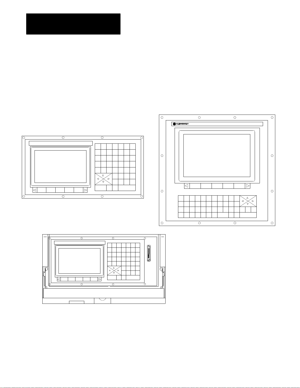
Figure 2.1 shows the different operator panels available. The color
operator panel has identical keys and softkeys in a slightly different
configuration. The portable operator panel has the same key locations as
the monochrome operator panel but can be removed from the 9/Series I/O
ring.
Figure 2.1
Operator Panels
9/SERIES
Monochrome Operator Panel
Removable Operator Panel
9
78
456
123
.
0:
N
+
_
$
=
CALC
!
G
O
X
P
_
I
F
Z
Y
A
W
R
M
Q
K
J
SHIFT
#
D
H
,
?
E
B
C
L
C
&
SP
T
S
[
]
SELECTSELECT
DISP
DEL
EOB
)
(
LINE
PROC
ColorOperatorPanel
(CRTand FlatPanel)
CAN
TRANSMIT
RES
CNTRL
19436
Page 27

Chapter 2
2-3
Basic Control Operation
2.1.1
Keyboard
Table 2.A explains the functions of keys on the operator panel keyboard.
In this manual, the names of operator panel keys appear between [ ]
symbols.
Table 2.A
Key Functions
Key Name Function
Addressand NumericKeys Usethese keys toenter alphabeticand numeric
characters. Ifa key has twocharactersprintedon it,
pressingit normallyentersthe upperleft character.Holding
downthe [SHIFT] key while pressingit entersthelower
rightcharacter.
CursorKeys • , • ,• , •
[SHIFT] and • or •
[SHIFT] and • or •
CalculationKey[CALC] Pressingthiskey enables a calculatortype function on the
Delete Key [DEL] Pressingthiskey deletes thecharacterto theleftofthe
[SHIFT] and [DEL] Pressingthis key deletesall keyed-indata currently
[CAN] Clearthemostrecently generated,activeerrormessage
Transmit Key [TRANSMIT] Thedata enteredand displayed ontheinput linesis sent to
BlockReset [RESET] Thisperforms a block reset. See page 2-4 .
ControlReset[RESET] +
[SHIFT]
DisplaySelect
[DISP SELECT]
End of Block [E.O.B.] Usethiskey to enteran End of Blockcharacterwhen
[PROC SELECT] This keyis used for dual processlathe systemsonly.
[SHIFT] and [• ] Pressthe [SHIFT] keywhile holding down the[• ]
Usethese keys tomove the cursorleft,right,up and down
inthe data displayarea (lines4-21)of thescreen. We
refertothese keys as theleft,right,up, and downcursor
keys respectively.
Pressthe rightor leftcursorkeys while holdingdown the
[SHIFT] keyto move thecursor rightand lefton any
lineon which thatdata is being input. (normallyscreen
lines2-3).
Pressthe up ordown cursorkeywhile holding down the
[SHIFT] keyto roll thedisplay page forwardor
backwards.
control. Basicmathematicalexpressionsmay be evaluated
usingthis feature. For details,see page2-4.
cursoron inputlines.
displayedon input lines.
thecontrolwhen the [TRANSMIT] keyispressed,for
examplea password ora programblock.
Pressingthe resetkey whileholding down the shiftkey
performs a controlreset. See page 2-4 fordetails.
Usethis key todisplay the differentaxis positiondisplay
softkeys.
editinga programor when writingan MDIprogram.
Pressingthiskey toggles thecontrolfrom processto
process.
softkeytojump to theonline searchmonitorscreen. Press
thesekeys again toreturntothe previousscreen.
Page 28

Chapter 2
2-4
Basic Control Operation
Reset Operations
Block Reset
Use the block reset feature to force the control to skip the block execution.
To use the block reset function, program execution must be stopped. If
program execution stops before the control has completely finished the
block execution, a block reset aborts any portion of that block that has not
been executed. If program execution stops after the complete block
execution (as in the case of single block execution or a M00 etc.), the
control aborts the execution of the entire following block.
Press
[RESET] key on the operator panel to perform a block reset.
Control Reset
You can return the control to the default parameters, clear any
programming errors, and cancel any MDI commands by executing a
control reset. After you execute a control reset, any active program resets
to the first block; any programmed offsets or rotations of the coordinate
systems reset to default, and any MDI command is discarded. All of the
operating parameters return to the standard AMP-assigned values,
including any AMP-assigned G-codes active at power-up (except
Inch/Metric which remains in its last programmed state at control reset).
2.1.2
Calculator Function
Press the
[SHIFT] key to execute a control reset.
[RESET] key on the operator panel while holding down the
The 9/Series control is equipped to evaluate simple mathematical
expressions during the course of operation or programming.
To use the calculator function, line 2 of the screen must be blank. There
can be no prompt on the input line of the screen when you attempt to do
calculations. This completely disables any calculation operation when in
MDI mode. If you attempt to enter the calculator function while another
prompt is active, the control generates the error message “CANNOT
CALCULATE - PROMPT PRESENT.”
Use the calculator function as follows:
1. Press the
[CALC] key on the operator panel. The “CALC:”prompt
appears on the input line of the screen (line 2).
2. Enter a mathematical equation on the input line by pressing the
desired keys on the operator panel.
3. Press the
[TRANSMIT] key to evaluate the expression. The answer to
the expression is displayed on the input line.
Page 29

Chapter 2
2-5
Basic Control Operation
Expressions entered on the input line cannot exceed a total of 25
characters. Only numeric or special mathematical operation characters as
described below can be entered next to the “CALC:”prompt. Any
character that is not numeric or an operation character you enter on the
input line generates the error message “INVALID CHARACTER.”
The largest number you can enter for a calculate function is 214748367.
You cannot enter a number larger than 10 digits. If control displays a
number that is too large (longer than 10 digits), the control displays t he
error message “NUMBER IS OUT OF RANGE”. If the number entered or
calculated is greater than 10 digits, control displays the error message
“MATHOVERFLOW.”
Any fractional numbers cannot exceed .999999 (6 decimal places). If you
exceed this number of decimal places, the control automatically rounds off.
If this seventh digit is less than 5, the control rounds down. If this seventh
digit is 5 or greater, the control rounds up.
Any data entered on the input lines can be edited as described on page
2-41.
To disable the calculator function, press the
[CALC] key again. The
“CALC:”prompt is removed from the input line.
Use the characters in Table 2.B to indicate mathematical operations.
Table 2.B
Mathematical Operators
* Multiplication
/ Division
+ Addition
- Subtraction
[] Brackets
#
GetParamacroValue
The control executes mathematical operations in this order:
1. Any part of the expression that is between the brackets [ ] is
evaluated first. The values of paramacro variables are also
substituted for the #xxxx as the first operation performed.
2. Multiplication and division are evaluated second.
3. Addition and subtraction are evaluated last.
If the same level of evaluation is performed the left most operation takes
priority.
Page 30

Chapter 2
2-6
Basic Control Operation
Example 2.1
Mathematic Expressions
Expression Entered Result Displayed
12/4*3
12/[4*3] 1
12+2/2 13
[12+2]/2 7
12-4+3 11
12-[4+3]
9
5
Table 2.C lists the function commands available with the [CALC] key.
Table 2.C
Mathematical Functions
Function Meaning
SIN Sine (degrees)
COS Cosine(degrees)
TAN Tangent (degrees)
ATAN ArcTangent(degrees)
ASIN Arc Sine (degrees)
ACOS ArcCosine (degrees)
SQRT Square Root
ABS Absolute Value
BIN Conversion fromDecimalto Coded Decimal
BCD Conversion fromCoded Decimalto Decimal
ROUND RoundingOff(nearestwhole number)
FIX Truncation Down
FUP Truncation Up
LN Logarithms(naturallog)
EXP Exponent
When you program these functions, place the value that the function is to
be performed on in brackets, for example, SIN [10]. The exception to this
is the arc tangent function. The format for ATAN requires the division of
two values. For example, ATAN [10]/[2] is used to calculate the arc
tangent of 5.
The functions in Table 2.C are executed from left to right in a program
block. These functions are executed before the control executes any
mathematical operators like addition or subtraction. This order of
execution can only be changed by enclosing operations in brackets [ ].
Operations enclosed in brackets are executed first.
Page 31

Chapter 2
2-7
Basic Control Operation
Example 2.2
Format for [CALC] Functions
SIN[2] This evaluatesthe sine of2 degrees.
SQRT[14+2] Thisevaluates thesquare rootof 16.
SIN[SQRT[14+2]]
Thisevaluates thesineof the squareroot of16.
Example 2.3
Mathematical Function Examples
Expression Entered Result
SIN[90]
SQRT[16] 4.0
ABS[-4] 4.0
BIN[855] 357.0
BCD[357] 855.0
ROUND[12.5] 13.0
ROUND[12.4] 12.0
FIX[12.7] 12.0
FUP[12.2] 13.0
FUP[12.0] 12.0
LN[9] 2.197225
EXP[2]
1.0
7.389056
Important: Precaution must be taken when performing calculations within
the brackets [ ]. The operations within the bracket are performed first, and
then the function is performed on this resultant. For example
ROUND[2.8+2.6]; The result of this is 5.0
The values in the brackets are added together first and then rounded, not
rounded and then added together.
Paramacro Variables in CALC Operations
Any paramacro variable can be accessed through the CALC function.
Include a # sign followed by the paramacro variable number. When the
calculation is performed the value of that paramacro variable is substituted
into the equation. You can not change the value of paramacro variables
with the CALC function. Local parameters are only available for the
currently active nesting level of the control (main program, or one of four
nested macro programs). You can not perform calculations that contain
any paramacro variables if the control is currently executing a program
block. The control must be in either cycle stop state, or E-Stop.
Page 32
Chapter 2
2-8
Basic Control Operation
Example 2.4
CallingParamacro Variables with the CALC Function
Expression Entered Result Displayed
2.1.3
Softkeys
#100
12/#100*3 Divide12 by the currentvalue of#100
SIN[#31*3]
Displaycurrentvalue of variable#100
and multiply by 3
Multiply the value of#31 (forthe current
localparameternesting level)by 3 and
take the sine of thatresult
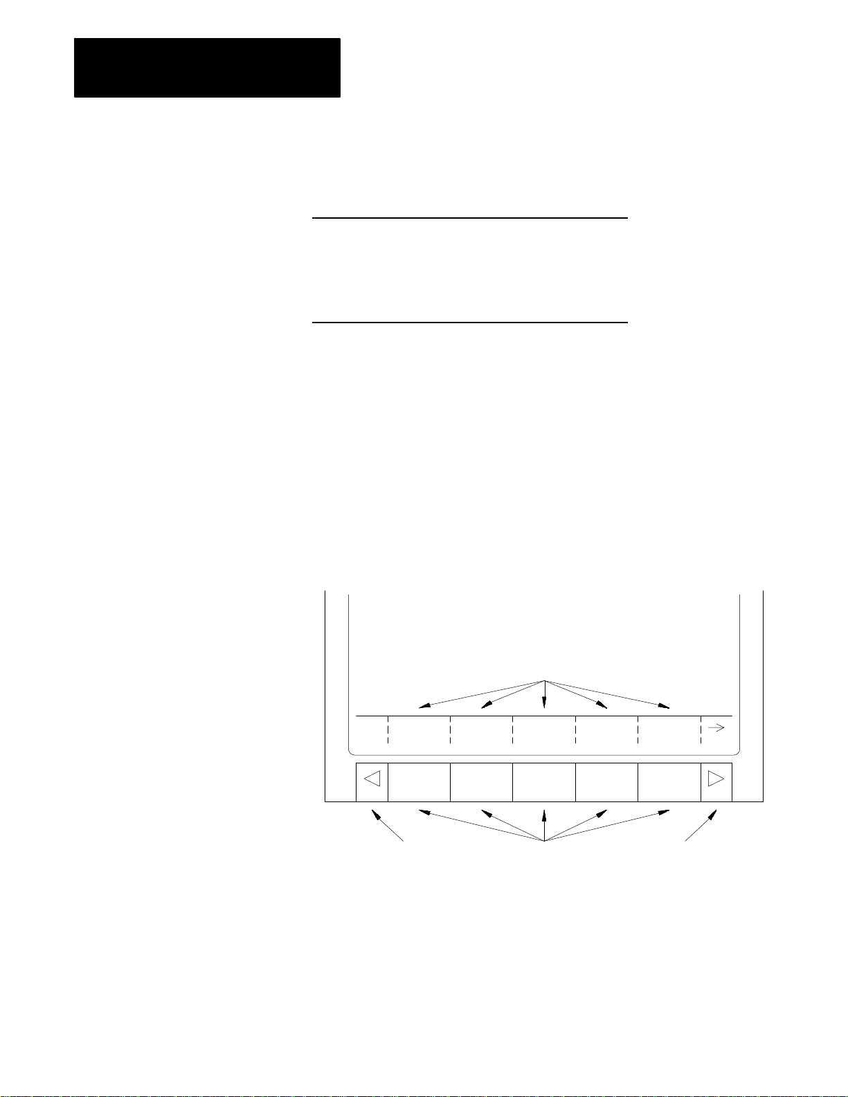
We use the term softkey to describe the row of 7 keys at the bottom of the
CRT. Each function is displayed on the CRT directly above the softkey.
Softkey names are shown between the { } symbols in this manual.
The control offers a variety of functions that can be initiated by using the
softkeys. The operator panel has 5 softkeys whose function names are
displayed in the softkey area at the bottom of the screen (lines 23-25 — see
Figure 2.2).
Figure 2.2
Softkeys
Datadisplay area
Softkey name displayarea
PRGRAM
MANAGE
Exit
OFFSET
MACRO
PARAM
Softkeys
PRGRAM
CHECK
SYSTEM
SUPORT
Continuekey
We often describe softkeys as being on a certain level, for example softkey
level 3. We use the level of the softkey to determine the location or
necessary path to reach that particular softkey function. For example, to
get to a softkey on level 3, you must press a specific softkey on level 1,
followed by a specific softkey on level 2. For a listing of all the softkeys
and their respective levels, refer to appendix A.
Page 33

Chapter 2
2-9
Basic Control Operation
Softkey level 1 is the initial softkey level the control displays at power-up.
Softkey level 1 always remains the same and all other levels are referenced
from softkey level 1.
The softkeys on opposite ends of the softkey row have a specific use that
remains standard throughout the different softkey levels.
On the: Is the:
left exitsoftkeydisplayed withthe up arrow{• }
right continuesoftkeydisplayed withthe rightarrow {• }
Use the exit softkey {• } on the far left to regress softkey levels. For
example, if you are currently on softkey level 3 and you press the exit
softkey, the softkeys change to the softkeys previously displayed on
softkey level 2. When you press the exit softkey while holding down
the shift key, the softkey display is returned to softkey level 1 regardless
of the current softkey level.
When more than 5 softkey functions are available on the same level, the
control activates the continue {
• } softkey at the far right of the softkey
area. When you press the continue softkey, the softkey functions
change to the next set of softkeys on that level.
Important: The continue softkey is not active when the number of softkey
functions on that level does not exceed 5.
For example:
(softkey level 1)
PRGRAM
MANAGE
OFFSET MACRO
PARAM
PRGRAM
CHECK
SYSTEM
SUPORT
When softkey level 1 is reached, the above set of softkeys is displayed.
Pressing the continue softkey {
• } displays the remaining softkey
functions on softkey level 1.
(softkey level 1)
FRONT
PANEL
ERROR
MESAGE
PASSWORD
SWITCH
LANG
The exit softkey is not displayed since the softkeys are already on softkey
level 1.
The softkey functions for level 1 and level 2 are explained in appendix A.
Softkey functions for level 3, or higher, are explained in the sections that
apply to their specific operations.
Page 34

Chapter 2
2-1
0
Basic Control Operation
To use a softkey function, press the plain, unmarked button directly below
the description of the softkey function.
Important: Some of the softkey functions are purchased as optional
features. This manual assumes that all available optional features have
been purchased for the machine. If an option is not purchased, the softkey
is blank.
2.1.4
CRT
The control can be purchased with a 9-inch monochrome monitor or a
12-inch color monitor.
Certain lines of the screen are dedicated to displaying specific information:
Lines: Display information:
line 1
machine/
systemmessage area
lines2-3
inputlines
lines4-20
datadisplay area
lines21-22
PAL message area
lines23-25
softkeydisplayarea
Ifan erroroccurs ora message is generatedforany reason during
machineoperationor programexecution,the controldisplays the
correspondingmachine/systemmessage in thisarea. Onlythe
highestpriority,mostcurrentmessageis displayed here.
Whenyou enter datausing the keyboard,the controldisplaysthe
characters correspondingto the keyspressed untilyou press the
[TRANSMIT] key. Somescreens can onlyhave line 2 as an input
line.
The controldisplaysaxis positiondata,listingof thepart program,tool
offset data,G-,M-,H-,T-,F-,S-,and D-codes,graphics,and other
data,as determinedby theselected display. Seechapter 8.
The controldisplaysany messages generatedby the control’sPAL
programin thisarea
The controldisplaysthe currentlyavailablesoftkey functionsin this
area.
Page 35
Chapter 2
2-1
1
Basic Control Operation
2.1.5
PortableOperatorPanel
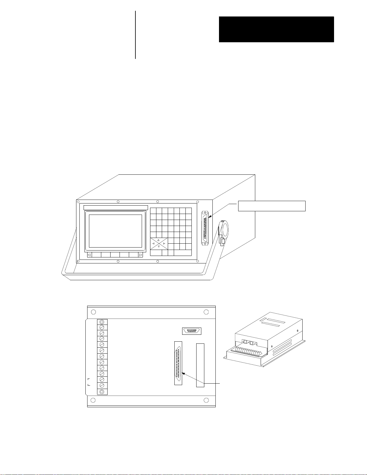
The control can be purchased with a 9-inch monochrome portable operator
panel. This panel can be attached or detached to the 9/Series I/O ring
operator panel interface assembly at any time without disrupting control
operation.
The portable operator panel is attached through a 10 ft portable operator
panel interface cable with a 3--pin D--shell connector at each end. One end
of the cable attaches to the front of the portable operator panel. The other
end attaches to the portable operator panel interface assembly. Refer to
your system installer’s documentation for details on attaching and
detaching the portable operator panel and the locations of the operator
panel interface assembly.
Removable Operator Panel
Connect Interface Assembly
(37 pin D Shell has pins)
Interface Assembly
GND12V GND5VGND 5V GND 5VCHA
GND
LH
AC
Video In CN19M
Operator Pnl. CN5
Vidoe Out CN4
Connect OperatorPanel
(37 pinD Shell has sockets)
Page 36

Chapter 2
2-1
2
Basic Control Operation
2.2
The MTBPanel
AUTO MDI MAN
Figure 2.3 shows the push-button MTB panel. Table 2.D explains the
functions of the switches and buttons on the MTB panel. Other optional or
custom MTB panels may be used. Refer to the documentation prepared by
your system installer for details.
We show button names found on the push--button MTB panel between the
< > symbols throughout this manual. The push-button MTB panel uses
defaults when you turn on power to the control. Table 2.D contains these
defaults.
Most of the switches or buttons on the MTB panel are configured by your
system installer’s PAL program. We assume that PALhas been written as
intended for normal operation. If a switch or button does not work the way
it is described in this manual, refer to documentation prepared by your
system installer.
Figure 2.3
Push-Button MTB Panel
MODE SELECT SPEED/MULTIPLY
JOG SELECT
CONT
INCR
LOWX1MEDL
X10
SPINDLESPEED
OVERRIDE
MED
X100
SPINDLE
CCW CW
ON
CYCLE
START
SINGLE
BLOCK
CYCLE
STOP
HAND HOME
AXIS
+X +4 --X
+Y TRVRS --Y
+Z - -4 --Z
MEDH
X1000
FUNCTION
F1
F3 F4
F5 F6
HIGH
X10000
F2
50 120
FEEDRATE
OVERRIDE
50 100
0
150
%
OFF
RAPID FEEDRATE
OVERRIDE
F1 25
50 100
ESTOP
RESET
OFF
19930
Page 37

Chapter 2
2-1
3
Selectstheoperationmode
Basic Control Operation
Table 2.D
Functions of the Buttons on the Push-Button MTB Panel
Switch orButton Name
MODE SELECT
JOG SELECT Selects the jogmethod tobe active in manualmode
SPEED/MULTIPLY Selectsan axis feedrateor axis feedamount multiplication ratioused in themanual mode. Each
How It Works = DefaultforPush-ButtonMTB Panel
AUTO ---- automaticmode
MANUAL-- -- manualmode
MDI---- manualdata inputmode
HANDWHEEL ---- HPG(hand pulse generator)jog
INCREMENTAL ---- incremental jog
CONTINUOUS---- continuous jog
HO M E -- -- m a c h i ne ho m e
selectionmodifiesthe activefeedrateby a value setin AMP. Modification also dependson the setting
of<JOG SELECT> asdescribedbelow:
• HANDWHEEL
Whenin handwheel jog mode,SPEED/MULTIPLYaltersthe handwheel resolutionby a factor
determinedin AMP. Yoursystem installersetsthe value for:
-LOWX1
-MEDLX10
-MEDL X100
You cannot usethevalues listedbelow forhandwheel jog:
-MEDH X1000
-HIGH X10000
• INCREMENTAL
Whenin incrementaljog mode,SPEED/M ULTIPLYaltersthe incrementaljogdistance
in AMPby yoursysteminstaller. Your systeminstallersetsa value forthe selections. The
incremental jog speed
<FEEDRATE OVERRIDE>.
• CONTINUOUS
Whenin continuous jog mode,SPEED/MULTIPLYacts as a feedrate selectionswitchwhich has
values set in AMPby yoursysteminstaller. Your systeminstaller sets a value for all 5 selections
independentlyforeach axis. <FEEDRATE OVERRIDE> can be used forspeed adjustments.
isfixed tomediumbutcan still be controlledby
byafactorset
Important: The valuesfor thedifferent<SPEED/MULTIPLY> selectionsareconfiguredby
your systeminstaller.
Page 38

Chapter 2
2-1
4
Basic Control Operation
Table 2.D
Functions of the Buttons on the Push-Button MTB Panel
Switch orButton Name
SPINDLE SPEED OVERRIDE Selects the overrideforprogrammedspindle speeds in 5%incrementswithin a rangeof 50% to120%.
SPINDLE or
SPINDLE DIRECTION
FEEDRATEOVERRIDE Selects a feedrateoverridepercentagefor thefeedrateprogrammedwith an F--wordin any of the
RAPIDFEEDRATE OVERRIDE Selects theoverride forrapid feedrates. SelectfromF1, 25%,50%, and 100% whereF1 is a rapid
EMERGENCY STOP This buttonstops machineoperationand disables the spindleand axis driveswhenpressed.
E-STOP RESET This buttonresetsan emergency stopconditionwhen pressed. Beforepressingthis buttonthe
CYCLE START The controlbegins orresumes partprogramexecution,MDI programexecution,or programcheck
CYCLE STOP The controlstopspart programexecution,MDIexecution,or programcheck when thisbuttonis
SINGLE BLOCK The controlexecutes orchecks one block ofa part programorMDIentryeach timethe
AXIS/DIRECTION Thesebuttonsare used formanual operations. They selectan axis and directionwhen
TRVRS Holdthisbutton down whileexecuting a continuousjog move tooverridetheactivefeedrate and jog an
F1-F4 Thefunctionsfor thesebuttonsare assignedby the systeminstaller. Referto the documentation
JOG RETRACT Usejog retracttojog a cuttingtool away fromtheworkpiece duringautomaticor MDIprogram
BLOCK RETRACE Toretracethe toolpath in a partprogram alreadyexecuted (up to15 blocks), pressthis button.
ON Turnson power tothe control.
OFF Turnsoffpower tothe control.
Selectsspindle rotation, clockwise(CW),spindle stop(OFF),counterclockwise (CCW). Can be
overriddenby any programmed spindle directioncommand.
feedrates modes (G93/G94/G95)andthereciprocationfeedrateprogrammedwithan E--word.
<FEEDRATE OVERRIDE> has a range of0% to 150%of the programmed feedrateand altersthe
programmed feedratein 10% increments. When setto 0%,the controlis effectively in feedhold.
feedrate override settingestablishedin AMP by thesystem installer.
conditionthatcaused the E-Stopshould beresolved.
whenthis buttonis pressed.
pressed. If pressedduring the executionof a programblock a cycle suspend stateoccurs.
<CYCLE START> buttonis pressed whensingle block is active.
<JOG SELECT> is setfor continuous,incremental, orhome. If<JOG SELECT> is setfor
handwheel,these buttonsselectan axis only. Directionis thendeterminedby handwheel rotation.
axisin rapid traverse.
preparedby the systeminstallerfor details.
execution.The controlcan retracethejog moves and returnthe cuttingtoolautomaticallytothe
workpieceby pressing<CYCLE START>. Refertochapter 7 formoreon this.
= DefaultforPush-ButtonMTB PanelHow It Works
Important: Many of the override switch settings may be disabled by
programming the correct M-code or setting a particular paramacro
parameter. Refer to their respective sections for details on these features.
Page 39

Chapter 2
2-1
5
Basic Control Operation
2.3
SoftwareMTB Panel
{FRONT PANEL}
The 9/Series control offers a software MTB panel that performs many of
the functions of an MTB panel. This feature uses softkeys instead of the
normal switches and buttons of a panel. If the control uses a standard
MTB panel (described on page 2-12), or some other custom panel, the
requests for operations from the panel takes priority. This means that
requests of the software MTB panel are ignored if another request is sent
from a standard or custom MTB panel.
The software MTB panel’s operation depends on PAL, especially if the
control uses either the standard or a custom MTB panel. Refer to
documentation prepared by your system installer for details on using the
software MTB panel. Your system installer uses PAL to disable the
{FRONT PANEL} softkey.
Important: By using the PAL flags $SWF1 and $SWF2, you can enable
and disable features available on the software front panel.
Refer to your PAL reference manual for additional information.
Page 40

Chapter 2
2-1
6
Basic Control Operation
The software MTB panel can control these features:
Feature Description
ModeSelect SelecteitherAutomatic, MDI,orManual modes as thecurrentoperatingmodeof thecontrol.
Rapid Traverse This featurereplacesthe feedratewhen executinga continuousjogmove withthe rapid feedrate.
FeedrateOverride Selectsa feedrateoverridepercentage forfeedratesprogrammedwithan F -word,in 10% incrementswithina
rangeof 0% to150%. When setto 0%,the controlis effectively in feedhold.
RapidFeedrate Override Selectsthe overrideforrapid feedrates. SelectfromF1, 25%,50%, and 100%,where F1 is a rapidfeedrate
override settingestablished inAMP by the systeminstaller.
SpindleDirection Selects spindlerotation,clockwise(CW),spindle stop (OFF),orcounterclockwise (CCW). Isoverridden by
anyprogrammed spindle directioncommand.
SpindleSpeed Override Selects theoverridefor programmedspindlespeeds in 5% incrementswithina range of50% to 120%.
DryRun Mode Places the controlin DryRun Mode. Thisreplaces feedrateswiththe DryRun feedrates. See chapter7.
BlockDelete Allowsthe activation of theblock delete feature“/or /1”(Seechapter 7). Block delete2 -- 9 are not available
with the{FRONT PANEL}.
M-Function Lock Allows selectM-,S-,T-, and B-codesto be ignored. See chapter 7.
OptionalStop This enables or disablesthe M01optionalstopcode. When this featureis“ON,”anM01 in a partprogram
stopsautomaticexecution. When this feature is “OFF,”anM01 in a partprogramis ignored. See chapter 10
fordetailson M01.
SingleBlock The controlexecutesor checks one block ofa partprogramorMDI entryeach timethe <CYCLE START>
buttonis pressedwhen this feature is on.
Mirror Image Mirrorsthe axiscommands in thepart programaround theselected axis. See chapter14.
AxisInhibit Prevents axis commandsfrombeing executed. The control simulatesaxismotion on inhibitedaxes by using
Acc/Decand feedrates; however,noactual axis motionforthe inhibitedaxes is generated.See chapter7.
JogtheAxes Allowsmanual motionstobe performedin any one of thejogging modes. Seesection4.1. Multi-axisjogs
maynot be performedby usingthe SoftwareMTBfeature.
Set Zero Changethe tool’scurrent positionin the workcoordinate systemto 0 forthe selecteda xis. This is done by
shiftingthework coordinatesystem. Seechapter 11.
BlockRetrace Thisallowsup to 15 partprogramblocks to be retraced during programexecutionand allow the toolto
automatically re-executethese blocks. Seechapter 7.
Jog Retract Allowthe toolto be manuallyjogged away fromthe partand then automatically returnthetool to thepart by
retracing the jogged moves. Up to 15 jogmovescan be remembered.Seechapter 7.
Cycle Start The controlbegins orresumes partprogramexecution,MDI programexecution,orprogram checkwhen you
pressthis button.
Cycle Stop T he control stopspartprogram execution,orprogram checkwhen you press thisbutton. If pressedduring the
executionof a programblock, a cycle suspend stateoccurs.
Page 41

Chapter 2
2-1
7
Basic Control Operation
Software MTB Panel Screen
To use the software MTB panel feature, follow these steps:
1. From the main menu screen, press the
{FRONT PANEL} softkey.
(softkey level 1)
PRGRAM
MANAGE
FRONT
PANEL
OFFSET MACRO
PARAM
ERROR
MESAGE
PASSWORD
PRGRAM
CHECK
SWITCH
LANG
SYSTEM
SUPORT
The Software MTB Panel screen displays the current status of the
alterable features.
SOFTWARE FRONT PANEL
MODE SELECT: MDI
RAPID TRAVERSE: OFF
FEEDRATE OVR: 0%
RAPID FEEDRATE OVR: 100%
SPINDLE DIRECTION: CW
SPINDLE SPEED OVR: 50%
DRY RUN MODE: OFF
BLOCK DELETE: OFF
M-FUNC LOCK: OFF
OPTIONAL STOP: OFF
SINGLE BLOCK: OFF
MIRROR IMAGE:
AXIS INHIBIT:
USE CURSOR FOR SELECTION
JOG
AXIS
PRGRAM
EXEC
2. Press the up or down cursor keys to select the function you want to
change. The selected function appears in reverse video.
3. Alter the value of the function by pressing the left or right cursor keys
(except for the Mirror Image and Axis Inhibit features). When you
select the Mirror Image or Axis Inhibit features, the softkey names
change to the axis names. Press the softkey that corresponds to the
axis (or axes) that you want to assign to these features.
Page 42

Chapter 2
2-1
8
Basic Control Operation
Jog Screen
We assume that you have performed the steps to display the Software
Front Panel screen. Make sure that the function selected on the Software
Front Panel screen is not the Mirror Image or the Axis Inhibit features.
1. Press the
{JOG AXIS} softkey.
(softkey level 2)
JOG
AXIS
This screen appears:
MEMORY MAN STOP
PRGRAM
EXEC
E-STOP
PROGRAM [mm] F 0.000 MMPM
Z 0.000 S 0.0
R X 0.000 T 0
C 359.99 FILENAME
SUB NAME
AXIS SELECT: X
JOG SELECT: CONTINUOUS
SPEED/MULTIPLY LOW
HPG NUMBER 0
SET
ZERO
JOG
AXIS +
JOG
AXIS -
2. Select the axis, jog type, speed multiply value (see chapter 4), and
HPG number (if HPG has been selected as the type of jog) by using
the up and down cursor keys, and the left and right cursor keys to
alter the value assigned to that function.
3. If the jog type is not HPG, then press the softkey that corresponds to
the direction on the selected axis to jog (if HPG is the jog type then
the direction of HPG rotation determines the direction to jog).
4. If you want to shift the current work coordinate system to force the
current tool position to be the zero point of the work coordinate
system, press the
{SET ZERO} softkey. The {SET ZERO} softkey does
not function when the control is in handwheel mode.
Page 43

Chapter 2
2-1
9
Basic Control Operation
ProgramExecute Screen
The following assumes that the steps have been performed to display the
Software Front Panel screen (see page 2-17). Make sure that the function
selected on the Software Front Panel screen is not the Mirror Image nor
the Axis Inhibit feature.
1. Press the
{PRGRAM EXEC} softkey.
(softkey level 2)
JOG
AXIS
PRGRAM
EXEC
This screen appears. Before you press this softkey, a program should
have already been selected for automatic execution as described in
chapter 7.
E-STOP
PROGRAM[ MM ] F 0.000 MMPM
Z 0.000 S 0.0
R X 0.000 T 0
C 359.99 FILENAME
SUB NAME
MEMORY MAN STOP
M100;
G90;
Z10;
G70;
BLOCK
RETRCE
JOG
RETRCT
CYCLE
START
CYCLE
STOP
Page 44

Chapter 2
2-2
0
Basic Control Operation
2. Select one of these softkey options:
block retrace
jog retract
cycle start
cycle stop
To Perform a: Press:
Cycle Start thesoftkeythat correspondstothe desired feature. Detailson these
features are describedin chapter7.
Cycle Stop the softkeythatcorresponds tothe desiredfeature. Details on these
features are describedin chapter7.
BlockRetrace the {BLOCK RETRCE} softkey. The controlautomatically
retraces the previouslyexecuted blockeach timeyou press. The tool
returnstothe startpointof Block Retracewhen you pressthe
{CYCLE START} softkey. Detailson BlockRetrace canbefound
inchapter 7.
Jog Retract the {JOG RETRCT} softkey. This callsup the jog retractscreen.
Select: theaxis, thetype of jog,the speed multiplyvalue (see
chapter4),or the HPGnumber (ifHPG has been selectedas the
typeof jog). Use the up and down cursorkeys toselect thefunction,
and theleftand right cursorkeys toalter thevalue assigned tothat
function.
3. If you selected JOG RETRACT, press the {JOG AXES +} or
{JOG AXES -} softkeys to select the direction to jog the axis. Press
the exit {
• } softkey when you complete the jog retract. The cutting
tool automatically retraces the jog moves you made when you pressed
{CYCLE START}. See chapter 7.
the
(softkey level 4)
SET
ZERO
JOG
AXES +
JOG
AXES-
Page 45

Chapter 2
2-2
1
Basic Control Operation
Figure 2.4
Jog Retract Software MTB Panel Screen
PROGRAM[ MM ] F 00000.000 MMPM
Z 00000.000 S 0
R X 00000.000 T 12
C 359.99 FILENAME
MEMORY MAN STOP
E-STOP
SUB NAME
2.4
PowerProcedures
2.4.1
Turning Power On
JOG
AXES+
JOG
AXES-
The basic procedure for turning power on and off is described in this
section. Refer to the documentation prepared by your system installer for
more specific procedures.
Follow this procedure to turn on power to the control:
1. Visually check to make sure that the control and the machine are in
normal operating conditions.
2. Press the power
Important: Do not touch any other buttons after you press the power
<ON> button.
<ON>
button until characters appear and remain on the screen.
3. If characters are not displayed on the screen within 15 seconds, press
the power
<OFF> button immediately.
Important: If the screen does not display characters after you press the
power
immediately press the power
To activate the main menu, press the
<ON> button within a reasonable warm up period (about 15 seconds),
<OFF> button and contact service personnel.
[TRANSMIT] key.
Page 46

Chapter 2
2-2
2
Basic Control Operation
You see the main menu screen:
E-STOP
PROGRAM[ MM ] F 00000.000 MMPM
Z 00000.000 S
R X 00000.000 T 12345
C 359.99 FILENAME
SUB NAME 9999
MEMORY 30000 MDI STOP
2.4.2
Turning Power OFF
(PAL messages)
PRGRAM
MANAGE
OFFSET MACRO
PARAM
PRGRAM
CHECK
SYSTEM
SUPORT
The softkeys available on the main menu screen are referred to as “level 1”
softkey functions. Some of the softkey functions are purchased as optional
and may not appear exactly as shown.
Follow this procedure to turn off power to the c ontrol:
CAUTION: To prevent damage to the machine, never turn off
power while a part program is being executed. Before turning
off power, make sure that the control is in CYCLE STOP.
1. Before you turn the power off, make sure that the control is in
CYCLE STOP.
2. Press the
<EMERGENCY STOP> button.
3. Make sure that power is turned off to all peripheral devices (tape
reader, tape punch, etc.) that are connected to the control.
4. Press the power
<OFF> button.
Page 47

Chapter 2
2-2
3
Basic Control Operation
2.5
Control Conditions at
Power-Up
After powering up the control or performing a control reset operation (see
page 2-4), the control assumes a number of initial operating conditions.
These are listed below:
Initial Password Access is assigned to the level that was active when
power was turned off (provided that level is a power-up level selected in
access control). If the active level when power is turned off is not a
power-up level, then the control defaults to the next lower level that is a
power-up level. See page 2-25 on access control.
The control is placed in E-Stop. The control is not allowed to come out
of E-Stop if the default AMP is loaded at power-up, or if there is no
PAL program loaded in the system. An appropriate error message is
displayed.
The control defaults to one G-code from each of these groups
(as set in AMP):
ModalGroup: G-code
1 G00 Rapid traverse
G01 Linear interpolation
2 G17 Plane Selected
G18 Plane Selected
G19 Plane Selected
3 G90 Absolute
G91 Incremental
4 G22 ProgrammableZone 2 and 3 (On)
G22.1 ProgrammableZ one 2 (Off)3 (On)
G23 ProgrammableZone 2 and 3 (Off)
G23.1 ProgrammableZ one 2 (On) 3 (Off)
5 G94 Feed per minute
G95 Feed per revolution
6* G70 Inch mode
G71 Metricmode
18 G07 Radius ProgrammingMode
G08 DiameterProgrammingMode
* This G codegroup is only establishedat powerup. A controlreset
willnot change thelast programmedstateof thismodal G codegroup.
To show the current operating conditions at any time, access the G-code
status screen as described in chapter 8. If you do this immediately after
power-up, it shows the initial operating conditions selected in AMP along
with other control power-up default conditions.
Page 48

Chapter 2
2-2
4
Basic Control Operation
2.6
Emergency StopOperations
Press the red <EMERGENCY STOP> button on the MTB panel (or any other
E-Stop switches installed on the machine) to stop operations regardless of
the condition of the control and the machine.
WARNING: To avoid damage to equipment or hazard to
personnel, the system installer should connect the
<EMERGENCY STOP> button, so that pressing the button opens the
circuit connected to the E-STOP STATUS terminal on the
control. This should disable the axis drives and the spindle
drive circuits, which should both be connected to this terminal.
Refer to the integration manual or the documentation prepared
by your system installer for details.
If equipped with the standard MTB panel, the following occurs
automatically after you press the
<EMERGENCY STOP> button:
The control displays “E-STOP”in the message area. This indicates that
the control is in the emergency stop state.
The red light in the <CYCLE STOP> button lights up to indicate that the
control is in the feedhold state.
2.6.1
EmergencyStop Reset
Power to all axis drive motors is turned off.
Important: If you press the
<EMERGENCY STOP> button while a part
program is running, program execution can resume at the point of
interruption. Refer to the mid-program start feature described in chapter 7.
Before resetting the emergency stop state, first locate and eliminate the
cause of the emergency stop.
If the
<EMERGENCY STOP> button is locked in the pressed position, it must
be released before the emergency stop state can be reset. The locked
button can be released in different ways depending on its type. With the
standard MTB panel, turn the button clockwise until it pops out.
To reset the emergency stop state, press the
<E-STOP RESET> button. Once
you push the E--Stop Reset button to clear the E--Stop state, the message,
“RESETTING E--STOP”displays to alert you that the control is attempting
to come out of E--Stop. After the cause of the E--Stop is resolved, the
control clears the “E--STOP”message. If the error condition is not cleared,
the “RESETTING E--STOP”message clears, but the “E--STOP”message
continues to flash as the control remains in E--Stop state.
Page 49

Chapter 2
2-2
5
Basic Control Operation
If the E-Stop occurred during program execution, the control may reset the
program when E-Stop reset is performed provided AMP is configured to
do so. Assuming that a control reset is performed, program execution
begins from the first block of the program when
<CYCLE START> is
pressed. If the current axis position prohibits this, the operator can
manually jog the axes clear, or consider executing a Mid-Program Start.
See chapter 7. If no control reset is performed, the remainder of the
program block being executed when E-Stop took place is aborted, and a
<CYCLE START> begins program execution at the next block.
Important: If the cause of the E-Stop is not eliminated, the circuit
connected to the E-STOP STATUS terminals remains open, and the
emergency stop state is not reset even when the
<E-STOP RESET> button is
pressed.
2.7
Access Control
Access control lets the system installer assign different functions of the
control to different users by means of a password. See section 2.7.2 for a
list of the functions that may be protected on the 9/Series control.
Each protectable function is assigned an access level that is made active
when the operator enters the password. When an access level is made
active, all functions that are assigned to that access level become available.
Access levels range between 1 and 8 where 1 is the highest level and 8 is
the lowest. A different password is assigned to each of the different access
levels. Eight passwords can be assigned.
Access control only applies to the front panel and softkey inputs. It cannot
control inputs from outside the system. For instance, if you control access
to the delete function, the user can’t delete a file, but a file can be deleted
by Mini-DNC software and by Data Highway with the 9/Series Data
Highway Plus Communication Module.
Important: If you do not want to use password protection, simply select
all functions as accessible for access level 8. Since access level 8 is
automatically available at power up, no password is necessary to access
any of the functions of the control. Password protection can also be
disabled by assigning a level at the power-up level by using the
“POWER UP LEVEL”parameter as described in section 2.7.2.
Page 50

Chapter 2
2-2
6
Basic Control Operation
2.7.1
Assigning Access Levels
and Passwords
This section describes setting or changing the functions assigned to a
particular access level, and changing the password used to activate that
access level.
Important: Functions or passwords can be assigned to another access
level only if:
If you have a higher access level than the access level you are
attempting to change, this means that if your password is assigned to
access level 6, you can only change the functions or passwords for
access levels 7 and 8. Functions, or a password, cannot be assigned to
access level 6 with a level 6 password.
Functions that are not available to the current user cannot be assigned to
other levels. If a user with access level 6 is changing a lower access
level functions, access level 6 must have access to any functions that are
changed. For example, if you are an access level 6 user, you do not
have access to
{SYSTEM SUPORT} to access level 7.
{SYSTEM SUPORT}, you cannot assign or remove
The current user must have access to the {ACCESS CONTROL} function.
To change the functions or password of a lower user number, follow these
steps:
1. Press the
(softkey level 1)
{PASSWORD} softkey.
PRGRAM
MANAGE
FRONT
PANEL
OFFSET MACRO
ERROR
MESAGE
PARAM
PASSWORD
PRGRAM
CHECK
SWITCH
LANG
SYSTEM
SUPORT
Page 51

Chapter 2
2-2
7
Basic Control Operation
2. Press the {ACCESS CONTRL} softkey. If the {ACCESS CONTRL}
softkey does not appear on the screen, the currently active access
level is not allowed to use the
password that has access to
(softkey level 2)
{ACCESS CONTRL} function. Enter a
{ACCESS CONTRL}.
ACCESS
CONTRL
This screen appears.
PASSWORD NAME -- (current password)
1 ACTIVE PROGRAM 18 ACCESS CONTROL
2 PROGRAM MANAGE 19 SWITCH LANGUAGE
3 EDIT PROGRAM 20 POWER UP LEVEL
4 COPY PROGRAM 21 TIME PARTS
5 RENAME PROGRAM 22 SI/OEM MESSAGE
6 DELETE PROGRAM 23 SCALING
7 DELETE ALL PROGRAM 24 CHANGE DIRECTORY
8 OFFSETS 25 AUX COMM
9 TOOL WEAR 26 SEARCH MONITOR
10 TOOL GEOMETRY 27
11 ACTIVE OFFSET 28
12 BACKUP OFFSET 29
13 QUICK CHECK 30
14 SYSTEM SUPPORT 31
15 PRGRAM PARAMETER 32
16 AMP 33
17 PARAMACRO PROG 34
UPDATE
01 02 03 04
& EXIT
NOTE: Some of theseprotected features are not available on 9/240 controls.
The softkey names change to display the 8 access levels along with
their corresponding passwords (provided that a password has been
assigned to that access level). Only the password names of access
levels that are lower than the currently active access level are shown.
Page 52

Chapter 2
2-2
8
Basic Control Operation
3. Press the softkey that corresponds to the access level that you want to
change. The pressed softkey appears in reverse video, and the
password name assigned to that access level is moved to the
“PASSWORD NAME.”
Important: If you attempt to change the functions available to an access
level that is equal to or higher than your the current access level, the error
message “ACCESS TO THIS LEVEL IS NOT ALLOWED.” You cannot
change the features that are assigned to your current access level or any
level that is higher than your own.
(softkey level 3)
UPDATE
& EXIT01(NAME)02(NAME)03(NAME)04(NAME)
4. If you want to enter or change the password for the selected level,
edit the password next to the “PASSWORDNAME”prompt by using
the input cursor as described on page 2-41 . If you also want to
change the functions for this password, move on to step 5. To save
the change made to the password and leave the access control screen
press the
{UPDATE & EXIT} softkey.
Functions that are currently available to the selected level are shown
in reverse video on the access level screen.
5. Use the up, down, right, and left cursor keys to select the functions to
change for that access level. The selected function is shown with a
flashing > to the left of the function.
6. Pressing the
[TRANSMIT] key toggles the function between accessible
and inaccessible for that access level.
Important: If you attempt to activate or deactivate a function that is not
accessible to the current user’s access level, the message “ACCESS TO
THIS FUNCTION NOT ALLOWED”is displayed. Only features that are
accessible to your the current access level can be selected as accessible or
inaccessible to a lower access level.
7. Press the
{UPDATE & EXIT} softkey to store the changes made to
accessible functions for the user levels and return the control to
softkey level 1.
(softkey level 3)
UPDATE
& EXIT01(NAME)02(NAME)03(NAME)04(NAME)
Page 53

Chapter 2
2-2
9
Basic Control Operation
2.7.2
PasswordProtectable
Functions
Parameter Name: Function becomesaccessible when parameter name is in reverse video:
1) ACTIVE PROGRAM Toaccess thesefeatures,both ACTIVEPROGRAMand PROGRAMMANAGE(number2below) mustbe
2)PROGRAM MANAGE • {ACTIVE PRGRAM} — All ofthe functionsin 1 above providedACTIVEPROGRAM (number1
3) EDIT PROGRAM {EDIT PRGRAM} — Editan existingprogramor createa new program.
4) COPY PROGRAM {COPY PRGRAM} — Copy a programto orfrommemory orstorage device.
5)RENAMEPROGRAM {RENAME PRGRAM}— Not renamea programname.
6)DELETE PROGRAM {DELETE PRGRAM} — Deletea singleprogramstoredin memory
7)DELETE ALL PROG {REFORM MEMORY}— Deleteall programscurrentlystoredin memory.
The following section describes the functions on the 9/Series control that
can be protected from an operator by the use of a password. If a user has
access to a function, the parameter associated with that function is shown
in reverse video on the access control screen.
Access to these functions can be controlled by passwords. Table 2.E
describes the function that is enabled (the operator can perform them) if
the parameter name is shown in reverse video. If the function is not shown
in reverse video, the function is protected and cannot be accessed.
Some parameters enable more than one function. If a parameter that
enables multiple functions is not selected as accessible, some of the
functions that would be enabled by the parameter can be enabled
individually by using other parameters.
Table 2.E
Password Protectable Functions
assignedto the user.
• {SELECT PRGRAM} — Selecta programforautomatic operation.
• {SEARCH} — Searcha partprogramfor a characterstringor sequencenumber tobegin program
executionat.
• {MID ST PRGRAM} — Startprogramexecutionfrom somelocation otherthanthebeginning and
stillsetall of theparameterspreviouslydefinedin the programactive.
• {T PATH GRAPH} — Enable theactive graphicsfeature.
• {CANCEL PRGRAM} — Disablethe currentlyactiveprogramfromexecution.
• {SEQ STOP} — Choosea sequence numberfor programautomaticprogramexecutionto stop at.
above)is also selected.
• {EDIT PRGRAM} — Editan existingprogramor createa new program.
• {DISPLY PRGRAM} — Displaya programusing the displayfunction.
• {COPY PRGRAM} — Copya program toor frommemory.
• {VERIFY PRGRAM} — Verify thattwoprograms areidentical usingthe verifyfunction.
• {COMENT} — Addcommentsto a programname inthedirectory.
• {RENAME PRGRAM} — Change aprogramname.
• {DELETE PRGRAM} — Deletea single programstoredin memory.
• {REFORM MEMORY} — Deleteall programscurrentlystoredin memory.
Page 54

Chapter 2
2-3
0
Basic Control Operation
Parameter Name: Function becomesaccessible when parameter name is in reverse video:
8) OFFSETS • {WORK CO-ORD} — Display and alter the preset work coordinate systemzero locations and the
9)TOOL WEAR {TOOL WEAR}— Displayand alter thetool wearamount tablefor thedifferenttools.
10)TOOL GEOMETRY {TOOL GEOMET} — Displayand alterthe toolgeometrytable.
11)ACTIVE OFFSET {ACTIVE OFFSET} — Changethecurrentlyactiveoffsetnumberwithoutrequiring theprogramming
12) BACKUP OFFSET {BACKUP OFFSET}— Makea copy of thecurrenttooloffsetdata.
13) QUICKCHECK {QUICK CHECK} — Use the syntax and formatchecker or the {QUICK CHECK} with graphics
14) SYSTEM SUPORT • {PRGRAM PARAM} — Displayand change the tablesfor programmable zones 1 and 2, the
15) PRGRAM
PARAMETERS
16)ONLINE AMP {AMP} — Displayand change the online adjustablemachine parameters.
17) PARAMACRO
PARAM
18) ACCESSCONTROL {ACCESS CONTRL} — Assign different functions to different accesslevels, change thecurrent
19) SWITCHLANGUAGE {SWITCH LANG.} — Change the currentdisplaysfromone language to another.
20) POWER-UP LEVEL When POWER-UP LEVEL is showninreverse video,it indicatesthatif poweris turnedoffwhenthis level
21)TIME PARTS • {SET TIME} — Change orreset timeparameters
22) SI/OEMMESSAGE • {ENTER MESSAGE} — Entera new message tobe displayed on the control’s power-upscreen.
Table 2.E
Password Protectable Functions
fixture offsetvalue.
• {TOOL WEAR} Displayand alter thetool wearamount tablesforthedifferenttools.
• {TOOL GEOMET} — Displayand alterthe tool geometrytables.
• {ACTIVE OFFSET} — Change thecurrentlyactiveoffsetnumberwithoutrequiringthe
programming of a differentoffsetnumber.
• {TOOL MANAGE} — Alterthetool lifeindicatorsand other machinespecifictool functions.
• {RANDOM TOOL} — Allowthe use ofthe randomtool tablesused to keep trackof different toolsin
differenttool pocket(see chapter20).
• {COORD ROTATE} — Rotateallof the workcoordinatesystemsfromthe machine coordinate
system.
• {BACKUP OFFSET} — Makea copy of thecurrenttool offsetdata.
ofa differentoffset number.
function.
single-digitfeedrates,andthe fixed-cycleoperating parameters.
• {AMP} — Changeany of theonline AMP features.
• {DEVICE SETUP} — Displayand change any of thecommunicationparametersforthe peripheral
devices.
• {MONI-TOR} — DisplaythecurrentI/Oconfigurations and the axismonitorfor followingerror,
distanceto marker,etc. Systemsuportdoes notprotecthotkey access tothe searchmonitorpage.
{PRGRAM PARAM} — Displayand change the tablesforprogrammablezones 1 and 2, thesingle-digit
feedrates, and the fixed-cycleoperatingparameters.
{MACRO PARAM} — Displayor change any ofthe values in theparamacrotables withoutusing
programming commands.
password,orview the functionsassigned tothe different accesslevels.
isactive,this level automatically becomesactive when poweris turnedback on. Ifthis isnot in reverse
video,it indicatesthatthe controldefaultsto level8 access controlat nextpower-up.
• {SET DATE} — Change orreset dataparameters
WhenT IME PARTS is notin reversevideo, theoperator canonly performthe followingfunctionson the
timeand partsscreen: RUNTIME,CYCLETIME,andLOT SIZE.
• {STORE BACKUP} — Storean enteredmessage forthe power-upscreen tobackup memory.
Page 55

Chapter 2
2-3
1
Basic Control Operation
ParameterName: Function becomes accessible when parameter name is inreverse video:
23) SCALING When SCALINGis not in reversevideo,the operatorstillhas access to the{SCALNG} softkey;however
valueson the screenmaynot be modified.
24) CHANGE
DIRECTORY
25)AUX COMM Allows access to the{AUX COMM} softkeythatsets DataHighway Communication Module Parameters.
26) SEARCHMONITOR Allowsaccess to the {SEARCH MONITOR} page thatallows searchingand monitoringof the control’s
27) PASSTHRUENABLE Allowsaccess to the {PT ENABLE} softkeythat enablesremoteI/Opass thruof AMP, PAL,and other
Allowsaccess tothe protectabledirectoryforfileedit,directexecutionselection,and encryptedoutput.
PAL program. This parameteralso protectshotkeyaccess to thesearch monitorpage.
ODSfeatures. The {PT ENABLE} softkeyisonlyavailable when AMPis configuredto disallowblock
transfers and the systemcontains remoteI/Ohardware thathas been enabled throughPAL.
2.7.3
EnteringPasswords
When you power-up, only functions that are not protectable and functions
that are assigned to access level 8 are available (provided that the active
level when power was turned off was not assigned the POWER UP
LEVEL feature). To access the functions that are assigned to a specific
access level, you must enter the password that corresponds to that access
level. To enter a password, follow these steps:
1. Press the
(softkey level 1)
{PASSWORD} softkey.
PRGRAM
OFFSET MACRO
MANAGE
FRONT
PANEL
ERROR
MESAGE
PARAM
PASSWORD
PRGRAM
CHECK
SWITCH
LANG
SYSTEM
SUPORT
Page 56

Chapter 2
2-3
2
Basic Control Operation
E-STOP
ENTER PASSWORD:
PROGRAM [INCH] F 0.000 MMPM
Z 00000.000 S 0
R X 00000.000 T 1
C 359.99
MEMORY MAN STOP
ACCESS
CONTRL
2. Enter the password you want to activate by typing it in on the input
line with the keys on the operator panel. The control displays * for
the characters you entered. If you make an error entering the
password, edit the input line as described on page 2-41.
3. When the password is correct, press the
[TRANSMIT] key. The access
level that the password is assigned to is made active, and the control
enables all of the functions that are assigned to that access level.
Page 57

Chapter 2
2-3
3
Basic Control Operation
2.8
Changing Operating Modes
The control provides 3 basic operation modes:
manual (MAN or MANUAL)
manual data input (MDI)
automatic (AUTO)
You can select a mode by using
using the
{FRONT PANEL} softkey. This is configurable by your system
<MODE SELECT> on the MTB panel, or
installer. Both means of selection cannot be available. Details on using
{FRONT PANEL} softkey are given on page 2-15.
the
Depending on the current control status, a mode change request cannot be
honored. Operating modes may not be changed if any of these are true:
The control is in E-Stop.
The control is in the cycle-suspend state. This results when a program
is halted during the execution of a block.
The control is executing a threading- or multiple-pass turning cycle.
Important: Your system installer may have written PAL to disable the use
of the
{FRONT PANEL} softkey to change modes. If this is the case, then
changing modes can be performed by using only
<MODE SELECT> on the
MTB panel.
Page 58

Chapter 2
2-3
4
Basic Control Operation
Manual mode
To operate the machine manually,
select MAN or MANUAL under <MODE SELECT>
or
press the {FRONT PANEL} softkey.
Use the left/right arrow keys to change the mode select options if using
{FRONT PANEL}.
For details on Manual Mode operation, see chapter 4.
Figure 2.5
Manual ModeScreen
PROGRAM[ MM ] F 00000.000 MMPM
Z 00000.000 S 0
R X 00000.000 T 1
C 359.99
MEMORY MAN STOP N 99999
(First 4 blocks of
program shown here)
(PAL messages)
PRGRAM
MANAGE
OFFSET MACRO
PARAM
PRGRAM
CHECK
E-STOP
SYSTEM
SUPORT
Page 59

Chapter 2
2-3
5
Basic Control Operation
MDI mode
To operate the machine in MDI mode,
select MDI under <MODE SELECT>
or
press the {FRONT PANEL} softkey
Use left/right arrow keys to change mode select options if using
{FRONT PANEL}.
For details on MDI operation, see page 4-11.
Figure 2.6
MDI Mode Screen
MDI:
PROGRAM[ MM ] F 0 MMPM
Z 00000.000 S
R X 00000.000 T 1
C 359.99
MEMORY MDI STOP N 99999
(First 4 blocks
of MDI shown here)
(PAL messages)
PRGRAM
MANAGE
OFFSET MACRO
PARAM
PRGRAM
CHECK
E-STOP
SYSTEM
SUPORT
Page 60

Chapter 2
2-3
6
Basic Control Operation
Automaticmode
To operate the machine automatically,
select AUTO under <MODE SELECT>
or
press the {FRONT PANEL} softkey
Use left/right arrow keys to select mode options if using
For details on automatic operation, see chapter 7.
Figure 2.7
Automatic Operation Screen
PROGRAM[ MM ] F 0 MMPM
Z 00000.000 S 0
R X 00000.000 T 1
C 359.99
MEMORY AUTO STOP N 99999
(First 4 blocks of
program shown here)
(PAL messages)
{FRONT PANEL}.
E-STOP
PRGRAM
MANAGE
OFFSET MACRO
PARAM
PRGRAM
CHECK
SYSTEM
SUPORT
Page 61

Chapter 2
2-3
7
Basic Control Operation
2.9
Displaying System and
MachineMessages
The control has two screens dedicated to displaying messages. The
MESSAGE ACTIVE screen displays up to nine of the most current
system messages and ten of the most current machine (logic generated)
messages at a time. The MESSAGE LOG screen displays a log of up to
99 system messages and a separate log of up to 99 machine messages that
occurred since the last time memory was cleared. For single process
controls, this log displays up to 11 pages of messages (99 messages total)
and up to six pages per process for dual process systems.
Important: The control automatically displays the highest priority, single,
active message on all screens (other than the message screen) on line 1 of
the CRT. If more than one message occurs with the same priority, the
control displays the most recent message (provided no other message is
active with a higher priority).
Use the MESSAGE ACTIVE screen to display all the messages that are
currently active, or the MESSAGE LOG screen to display a log of the
recorded messages. To access these message screens, follow these steps:
1. From the main menu press the continue {• } softkey to change the
softkey functions.
(softkey level 1)
PRGRAM
MANAGE
OFFSET MACRO
PARAM
PRGRAM
CHECK
SYSTEM
SUPORT
2. Press the {ERROR MESAGE} softkey to enter the MESSAGE ACTIVE
screen shown in Figure 2.8.
(softkey level 1)
FRONT
PANEL
ERROR
MESAGE
PASSWORD
SWITCH
LANG
The control displays the currently active messages in sections
dedicated to:
system messages in the top half of the screen
machine messages (logic generated) in the bottom half of the
screen
Page 62

Chapter 2
2-3
8
Basic Control Operation
Figure 2.8
Message Active Display Screen
MESSAGE ACTIVE
SYSTEM MESSAGE
(The system error messages are displayed in this area)
MACHINE MESSAGE
(The logic messages are displayed in this area)
ERROR
LOG
CLEAR
ACTIVE
This is the information displayed on the MESSAGE ACTIVE screen. The
control displays up to 9 active system messages and up to 10 machine
messages. The machine messages represent the currently active logic
messages located on 13 lines through 22 of the 9/Series display screen.
Important: For a listing of system messages and a brief description, refer
to appendix B. For a description of machine messages, refer to the
documentation prepared by your system installer.
3. Press the
{ERROR LOG} softkey to enter the MESSAGE LOG screen
shown in Figure 2.9.
(softkey level 2)
ERROR
LOG
CLEAR
ACTIVE
The control displays the logged messages in sections dedicated to:
system logged messages in the top half of the screen
machine logged messages (logic generated) in the bottom half of
the screen
Page 63

2-3
9
Figure 2.9
Message Log Display Screen
MESSAGE LOG PAGE 1 of 9
SYSTEM MESSAGE
(The logged system error messages are displayed in
this area)
MACHINE MESSAGE
(The logged logic messages are displayed in this area)
Chapter 2
Basic Control Operation
ACTIVE
ERRORS
TIME
STAMPS
This is the information displayed on the MESSAGE LOG screen. The
control displays up to 99 system messages and up to 99 machine messages.
These are the most recent system messages and machine messages that
occurred on the control since memory was last cleared. To display more
messages, press the [• ] key while holding the[SHIFT]key. The next page
of the logged messages displays.
Press the {TIME STAMPS} softkey to view the date and time of when
each logged system message and machine message occurred.
Pressing this softkey may cause part of the messages text to be
overlaid by the date and time data. To display the full messages text ,
press the {FULL MESAGE} softkey.
4. Press the {ACTIVE ERRORS} softkeytoreturntothe
MESSAGE ACTIVE screen.
(softkey level 2)
ACTIVE
ERRORS
TIME
STAMPS
5. To return to softkey level 1 press the exit {• } softkey while holding
the [SHIFT] key.
Page 64

Chapter 2
2-4
0
Basic Control Operation
2.9.1
ClearingActive Messages
{CLEAR ACTIVE}
After the cause of a machine or system message has been resolved, some
messages remain displayed on all screens until you clear them.
CAUTION: Not clearing the old messages from the screen can
prevent messages that are generated later from being displayed.
This occurs when the old resolved message has a higher priority
than the newly generated message. The new message is still
displayed on the message display screen as an active message,
but does not appear in the message area of other screens.
Active messages are cleared from the screen in this way:
Press the [CAN] key to clear the most recent active messages
individually.
Clear all active messages from the error message display screen by
pressing the
(softkey level 2)
{CLEAR ACTIVE} softkey.
ERROR
LOG
CLEAR
ACTIVE
Important: Clearing active messages does not correct the problem that
caused the error; it only clears the message from the active file.
Page 65

Chapter 2
2-4
1
Basic Control Operation
2.10
The Input Cursor
The input cursor is the cursor located on lines 2 and 3 of the screen. It is
available when you need to input data by using the operator panel (as
needed in MDI mode, for example). The following section is a description
of how to move the cursor and edit data on the input line by using the keys
on the operator panel.
CursorOperation: Description:
Movingthe inputcursor To movethe cursorrightandleft in theinput area,press and
holdthe [SHIFT] key while pressingthe leftand rightcursor
keys. To move the cursor between line 2 and 3 use theleft
and rightcursorkeys while holdingthe [SHIFT] key. The
up and downcursor keyscannotbe used. The inputcursor
wrapsaround when itreaches theend of the screen.
Inserting characters To insertcharactersinto existingdata ontheinput lines,move
thecursor asdescribed above. Placethe cursorjust tothe
rightofthelocationto insertdata. Anydata typed inby using
theoperatorpanel is insertedjust tothe leftof thecursor.
DeletingCharacters Todelete characterson theinput lines movethe cursorto the
rightofthecharacterto delete. Pressingthe[DEL] key
deletesthe charactertothe leftof thecursor intheinput line.
Deletingall characters on
theinput line
Sendinginformation Tosend information tothecontrolfrominput line pressthe
To delete all enteredcharacterson theinput lines pressthe
[DEL] keywhile holding down the[SHIFT] key. All
characters on the inputline are deleted.
[TRANSMIT] key. Allinformationon theinputline is sentto
thecontrol.
2.11
{REFORM MEMORY}
It is sometimes necessary to perform a Reform Memory operation to clear
memory. This is often necessary after one of the following occurs:
the amount of RAM memory that can be used by PAL is changed in
AMP
a new PAL program has been sent to the control (downloading PAL
does not always make it necessary to format)
volatile memory has failed either from the super cap loosing power or
from the battery backup loosing power.
You must format any time the control displays the error message
“MEMORY CRASH -- REFORMAT.”
This operation can also be performed when you want to delete all part
programs in control memory.
After a format operation is performed, it is not necessary to re-install
AMP or PAL.
Page 66

Chapter 2
2-4
2
Basic Control Operation
CAUTION: The {REFORM MEMORY} function erases all part
programs that are stored in control memory.
To reformat control memory and delete all programs stored in memory,
follow these steps:
1. Press the
(softkey level 1)
{PRGRAM MANAGE} softkey.
PRGRAM
MANAGE
FRONT
PANEL
OFFSET MACRO
ERROR
MESAGE
PARAM
PASSWORD
2. Press the {REFORM MEMORY} softkey.
(softkey level 2)
ACTIVE
PRGRAM
DELETE
PRGRAM
REFORM
MEMORY
EDIT
PRGRAM
VERFY
PRGRAM
CHANGE
DIR
RESTRT
PRGRAM
PRGRAM
COMENT
PRGRAM
CHECK
SWITCH
LANG
DISPLY
PRGRAM
RENAME
PRGRAM
SYSTEM
SUPORT
COPY
PRGRAM
INPUT
DEVICE
3. Press the {REFORM YES} softkey. All programs that are stored in
control memory are deleted. To abort the operation, press the
{REFORM NO} softkey.
(softkey level 3)
REFORM
YES
REFORM
NO
It can take several seconds for the control to complete the operation.
During this period, the softkeys on the operator panel are rendered
inoperative.
Page 67

Chapter 2
2-4
3
Basic Control Operation
2.12
Removingan Axis
(Axis Detach)
2.13
Time Parts Count
DisplayFeature
This feature allows the removal of a rotary table or other axis attachment
from a machine. When activated, the control ignores messages that may
occur resulting from the loss of feedback from a removed axis such as
servo errors, etc.
Important: This feature removes the selected axis from the control as an
active axis. Any attempt to move the removed axis results in an error.
This means that part programs that use the removed axis name cannot be
executed. Jog moves and MDI commands that attempt to move the
removedaxisalsoresultinanerror.
This feature can be enabled in AMP. The axis must be selected as
“Detached”to be considered removed. Refer to the documentation
supplied by your system installer for the necessary steps involved in
detaching an axis or physically removing axis hardware from your
machine.
The Time Parts Count Display logs data relevant to part program execution
such as number of workpieces cut, cycle time, lot size, and remaining
workpieces. This data can be displayed and altered through the Time Parts
screen.
There are 3 levels of access to the Time Parts screen. They are listed
below in order of most restrictive to least restrictive. Refer to page 2-25
for details on password protection and access control.
Access: Protection:
No Restricts operatorfromTime Partsscreenentirely(softkey
{TIME PARTS} notaccessible). Accomplishedby denying accessto
“ActiveProgram.”
Operator Restricts operatorfromsetting“Date”or“Time”(softkeys {SET TIME}
and {SET DATE} do notappear). Alsorestrictsoperatorfromsetting
“Power-ontime/overall”and “Workpiecescut/overall.” Accomplishedby
denyingaccess to “TimeParts.”
Supervisor Fullaccess toall featuresof theTime Partsscreen.
To access the Time Parts screen, follow these steps:
1. Press the
(softkey level 1)
{PRGRAM MANAGE} softkey.
PRGRAM
MANAGE
OFFSET MACRO
PARAM
PRGRAM
CHECK
SYSTEM
SUPORT
FRONT
PANEL
ERROR
MESAGE
PASSWORD
SWITCH
LANG
Page 68

Chapter 2
2-4
4
Basic Control Operation
2. Press the {ACTIVE PRGRAM} softkey.
(softkey level 2)
ACTIVE
PRGRAM
DELETE
PRGRAM
REFORM
MEMORY
EDIT
PRGRAM
VERFY
PRGRAM
CHANGE
DIR
RESTRT
PRGRAM
PRGRAM
COMENT
DISPLY
PRGRAM
RENAME
PRGRAM
COPY
PRGRAM
INPUT
DEVICE
3. Press the {TIME PARTS} softkey. This generates the screen shown in
Figure 2.10.
(softkey level 3)
DE-ACT
PRGRAM
SEQ
STOP
SEARCH MID ST
PRGRAM
T PATH
GRAPH
T PATH
DISABL
TIME
PARTS
Page 69

2-4
5
You see the Time Parts screen:
Figure 2.10
Time Parts Screen
PROGRAM DATE TIME
XXXXXXXX MM/DD/YY HH:MM:SS
POWER-ON TIME/OVERALL : 99999:59:59
WORKPIECES CUT/OVERALL : 9999999999
RUN TIME : 99999:59:59
POWER-ON TIME/AFTER RESET : 99999:59:59
CYCLE TIME : 99999:59:59
WORKPIECES CUT/AFTER RESET : 9999999999
LOT SIZE : 9999999999
REMAINING WORKPIECES : 999999999
LOT COMPLETION FLAG : 0
Chapter 2
Basic Control Operation
(PAL messages)
SET
TIME
SET
DATE
ED PRT
INFO
Important: Some softkeys shown in Figure 2.10 might not appear on your
system due to restricted access. Refer to the beginning of this section and
page 2-25 for details.
You can modify the values on this screen. Press the
{SET DATE},orthe{SET TIME} softkeys as explained in the Screen Field
{ED PRT INFO},
Definitions that follow.
Press the exit softkey {
• } to save changes and return to the “Active
Program”screen.
Page 70

Chapter 2
2-4
6
Basic Control Operation
Time Part Screen Field Definitions
Program -- is the currently active part program, displayed automatically
by the control.
Date -- is the current date setting. To change this setting:
1. Press the
{SET DATE} softkey, provided that you have
supervisor-level access.
You are prompted for a new date with a line that displays the current
date setting.
2. Press the
[DEL] key to erase the characters displayed.
3. Type in the new date.
You must use one of these formats:
Format: Language:
Month/ Day/ Year English
Year /Month /Day Japanese
Day/ Month/ Year German
Time -- is the current 24-hour time setting. It can be changed by pressing
the
{SET TIME} softkey, provided that you have supervisor-level access.
You are prompted for a new time with a line that displays the current time
setting. Change the current setting by pressing the
[DEL] keytoerasethe
characters displayed and then typing in the new time. You must enter
using the format Hours:Minutes:Seconds. For example, 2:00 pm should be
entered as 14:00:00.
Power-on Time/Overall -- indicates the total accumulated time that the
control has been ON. This value is saved in backup memory each time the
control is powered off, so it is restored at its previous value each time the
control is turned ON. To clear this field to zero:
1. Press the
{ED PRT INFO} softkey, provided that you have
supervisor-level access.
2. Press the up or down cursor keys to move to this field or the next
field without changing the current value.
3. Enter a Y at the prompt for this field.
4. Press [TRANSMIT] to clear the current value.
Page 71

Chapter 2
2-4
7
Basic Control Operation
Workpieces Cut/Overall -- indicates the total number of part programs
executed to completion by the control. Use this field to determine the need
for periodic checkups or as a statement of warranty. This counter is
incremented by one each time the control encounters an M02, M30, or an
M99 in a main part program (M99 in a subprogram does not increment this
counter, though M02 or M30 does). To clear this field to zero:
1. Press the
{ED PRT INFO} softkey, provided that you have
supervisor-level access.
2. Press the up or down cursor keys to move to this field or the next
field without changing the current value.
3. Enter a Y at the prompt for this field.
4. Press [TRANSMIT] to clear the current value.
Run Time -- indicates the total accumulated time that part programs were
executing with the control in automatic mode. Use this field with
“Power-on Time/After Reset”to estimate the utilization ratio of the
machine. To clear this field to zero:
1. Press the
{ED PRT INFO} softkey if you have either operator-level or
supervisor-level access.
2. Press the up or down cursor keys to move to this field or the next
field without changing the current value.
3. Enter a Y at the prompt for this field.
4. Press [TRANSMIT] to clear the current value.
Power-on Time/After Reset -- indicates the total accumulated time that
the control has been ON. This value is saved in backup memory each time
the control is powered off, so it is restored at its previous value each time
the control is turned ON. Use this field with “Run Time”to estimate the
utilization ratio of the machine. The value for this field is cleared to zero
when the “Run Time”field is cleared to zero; it cannot be changed
independently.
Page 72

Chapter 2
2-4
8
Basic Control Operation
Cycle Time -- indicates the elapsed execution time for each individual part
program. Cycle time begins counting when the cycle-start button is
pressed and ends when an M02 reset or M30 is encountered. To reset this
field to zero, use one of three methods:
press the cycle-start button to initiate program execution
turn off the control power
follow these steps:
1. Press the
{ED PRT INFO} softkey if you have either operator-level or
supervisor-level access.
2. Press the up or down cursor keys to move to this field or the next
field without changing the current value.
3. Enter a Y at the prompt for this field.
4. Press [TRANSMIT] to clear the current value.
Workpieces Cut/After Reset -- indicates the total number of part
programs executed to completion by the control since the last time “Run
Time”was reset. This counter is incremented by one each time the control
encounters an M02, M30 or an M99 in a main part program (M99 in a
subprogram does not increment this counter, though M02 or M30 does).
The value for this field is cleared to zero when the “Run Time”field is
cleared to zero; it cannot be changed independently.
Lot Size -- is the number of times you need to execute this particular part
program. To enter a new number:
1. Press the
{ED PRT INFO} softkey if you have either operator-level or
supervisor-level access.
2. Press the up or down cursor keys to move to this field or the next
field without changing the current value.
3. Enter a numeric value at the prompt for this field.
4. Press
[TRANSMIT] to change the current value.
Page 73

Chapter 2
2-4
9
Basic Control Operation
Remaining Workpieces -- indicates the number of workpieces that still
need to be cut in the lot. The value for this field is automatically set equal
to the lot size each time the “Lot Size”value is changed. When the control
encounters an M02, M30, or M99 in a main part program, the remaining
workpieces field is decremented by one. The control tells the system
installers PAL program when the lot remaining size is zero. At this point,
press
<CYCLE START> to automatically set the field back to the “Lot Size”
value. Complete operation of this feature is somewhat PAL dependant.
Refer to the documentation supplied by your system installer.
Lot Completion Flag -- is automatically set to zero by the control
whenever a non-zero value is entered for “Lot Size.” It is set to one when
the “Remaining Workpieces”field reaches zero. It is again reset to zero
when the next cycle start occurs after the remaining workpieces field has
reached zero. Complete operation of this feature is somewhat PAL
dependant. See the documentation supplied by your system installer.
Press the exit softkey {
Program”screen.
END OF CHAPTER
• } to save changes and return to the “Active
Page 74

Chapter 2
2-5
0
Basic Control Operation
Page 75

Chapter
3
Offset Tables and Setup
3.0
ChapterOverview
3.1
Tool OffsetTable {TOOL
GEOMET}and {TOOL
WEAR}
In this chapter we describe the basics of job setup. Major topics include
how to:
use the offset table
set and display offset data
set and display work coordinate systems
set and display communication parameters
The offset tables are broken in to two major tables: the tool geometry
offset table and the wear offset table. Use the tool geometry offset table to
enter measured values that compensate for differences in tool mounting
and differences in tool dimensions. Use the wear offset table to enter
measured values that compensate for the amount of wear on a tool under
normal use. “Wear”means a non-reversible tool dimensional change.
This data can be entered into the offset tables:
Tool length offset data (TOOL GEOMETRY and TOOL WEAR.)
Cutter radius data (TOOL GEOMETRY and TOOL WEAR)
Parameters for the resolution of the offset data are determined by the
system installer in AMP. For more AMP information see your:
9/Series CNC AMP Reference Manual
Offline Development System (ODS) Software User Manual
Any setting smaller than the minimum unit set for axis motion is not
acceptable as offset data. The minimum value available to the system
installer is 0.00001 mm (0.000001 inch) with a maximum value of
99999999 (8 digits).
The D--word in a program will call values from the offset tables
corresponding to the tools diameter. An H--word in a program will call
values from the offset tables for tool length. When the H-- or D--word is
programmed the control pulls data from both the tool the geometry table
and the tool wear table. The value from the tool wear table is subtracted
from the value from the tool geometry table. The result is used by the
control as tool length offset or cutter c ompensation data.
For details on using tool offsets see chapter 20. For information on cutter
compensation see chapter 21.
3-1
Page 76

Chapter 3
OffsetTables and Setup
Figure 3.1
Offset Table Screen for Wear
TOOL OFFSET NUMBER:
TOOL WEAR TABLE X PAGE 1 OF 4
NO. LENGTH (DIAMETER)
1 .5321 .0234 [INCH]
2 .4421 .0142 [INCH]
3 .0243 .0888 [INCH]
4 .0156 .0791 [INCH]
5 .0265 .0532 [INCH]
6 .081 .043 [ MM ]
7 .032 .022 [ MM ]
8 .0000 .0000 [INCH]
9 .0000 .0000 [INCH]
10 .0000 .0000 [INCH]
11 .0000 .0000 [INCH]
12 .0000 .0000 [INCH]
13 .0000 .0000 [INCH]
3.1.1
Tool OffsetDimensional
Parameters
SEARCH
NUMBER
REPLCE
VALUE
ADD TO
VALUE
ACTIVE
OFFSET
MORE
OFFSET
Tool Offset Numbers(Geometry and WearTable)
Tool offset numbers are called out in a part program through use of D-- and
H--words. D-- and H--words specify a one, two, or three digit offset
number. The control then accesses the value assigned to that offset number
in the offset table. The offset number is in the far left column on the offset
screen. Offset number “00”is not a valid offset number to enter data under,
but can be used to cancel tool offsets.
For more on calling offset numbers refer to chapter 20.
Tool LengthOffset Data (Geometry Table)
The tool length offset function is used to compensate for the difference
between the tool position (or tool length) as mounted in the spindle and the
tool length assumed in writing a part program. By using the tool length
offset function, a programmer can write a part program without further
concern for tool mounting.
3-2
Page 77

Chapter 3
OffsetTable and Setup
The system installer determines in AMP which axis (or axes) are used by
the control as the tool length axis. Refer to documentation prepared by the
system installer for details on what axes have been selected for the tool
length axis. This manual assumes that the Z axis is used as the tool length
axis.
Figure 3.2
Tool Length Offset
gauge
line
amount of
tool offset
cutting tool
The term “gauge line”is used to define the precise point on the spindle or
tool holder from which all programmed tool paths originate. Offsets refer
to the distance from this gauge line to the end of the tool that contacts the
part being cut.
For tool length offset data, measure the value for the Z axis from the gauge
line to the end of the cutting tool. The values may be entered as either
positive or negative values depending on which G-code is used to activate
the offset (G43 or G44).
Important: For a typical end milling machine (with tool/chuck
configuration similar to Figure 3.2), keep the following in mind. When
programming tool offsets with a G43, the geometry offset value should be
positive and the wear offset data should be negative when entered in the
offset tables. When programming tool length offsets with a G44, the
geometry offset value should be negative and the wear offset data should
be positive when entered into the offset tables.
3-3
Page 78

Chapter 3
OffsetTables and Setup
Tool Diameter Compensation Data (Geometry Table)
To cut a workpiece using the side face of the cutting tool, it is more
convenient to write the part program so that the center of the tool moves
along the shape of the workpiece. Since all cutting tools have a diameter, a
program written for moving the center of the tool must somehow
“compensate”for the tool’sradius.
The system installer determines if radius or diameter values are entered in
the offset table. This manual assumes that the system installer requires
diameter values to be entered.
The control can compensate for this difference using the c utter
compensation feature discussed in chapter 21.
Cutter compensation require that the diameter of the cutting tool be
entered. Call the tool diameter value from the offset tables by
programming a D--word in a part program. Note that the control will
automatically convert the tool diameter to a radius value when necessary.
Tool Length WearData (Wear Table)
The tool length wear feature takes into account the wear (change in
length) that the end of a tool will incur from normal usage. Enter a value
in the wear table that is equal to the difference in tool length as entered in
the geometry table and the actual tool length. The value entered as tool
length wear is subtracted from the current value for tool length taken from
the geometry offset table when an H--word is designated in a part program.
This feature allows the compensation for slight changes in tool length
without the need to change the tool geometry table. Then when a worn
tool is replaced with an identical tool the wear offset needs to be reset to
zero. The tool geometry value should never need to be altered once the
initial value is entered as long as identical tools are always used when
replacing tools.
Important: For a typical end milling machine (with tool/chuck
configuration similar to Figure 3.2), keep the following in mind. When
programming tool offsets with a G43, the geometry offset value should be
positive and the wear offset data should be negative when entered in the
offset tables. When programming tool length offsets with a G44, the
geometry offset value should be negative and the wear offset data should
be positive when entered into the offset tables.
3-4
Page 79

Chapter 3
OffsetTable and Setup
Tool DiameterWear CompensationData (Wear Table)
The tool diameter wear compensation feature takes into account the wear
that a tool diameter will incur from normal usage. Enter a value in the
wear table that is equal to the difference in tool diameter as entered in the
geometry table and the actual tool diameter. The value entered as tool
diameter wear is subtracted from the current value for the tool diameter
taken from the geometry offset table when a D--word is designated in a part
program.
The system installer determines if radius or diameter values are entered in
the offset table. This manual assumes that the system installer requires
diameter values to be entered.
This feature allows the compensation for slight changes in tool diameter
without the need to change the tool geometry table. Then when a worn
tool is replaced with an identical tool the wear offset needs to be reset to
zero. The tool geometry value should never need to be altered once the
initial value is entered as long as identical tools are always used when
replacing tools.
3.1.2
Setting ToolOffset Tables
There are six methods for modifying tool offset tables. These are
discussed in the following chapters and sections:
Using {MEASURE} (section 3.1.3)
Programming G10s (chapter 20)
Skip functions using a probe (chapter 27)
Setting Paramacro System Parameters (chapter 28)
Altering through the PAL program
When PAL is used to modify either the work coordinate system
tables or the tool offset tables, cutter compensation should not be
active (G40 mode). If cutter compensation is active, be aware that
the new offset will not be placed in part program set-up buffers that
have already been read into control memory. This will result in the
offset not being activated until several program blocks after the
current block. The number of setup buffers is dependent on the
number of block retrace steps configured in AMP and what software
features are currently being used.
The sixth method, and the one discussed here, lets you directly key in to
the offset table offset data that is manually measured.
3-5
Page 80

Chapter 3
OffsetTables and Setup
Important: In order for newly modified tool offsets to become
immediately active, cutter compensation must be off (G40 mode). If it is
on (G41/G42 mode), the control generates the error message “CHANGE
NOT MADE IN BUFFERED BLOCKS”. This indicates that the control is
still using the old offset values and must first run several program blocks
before using the new offsets values. The new offsets may then be activated
too late for your particular application.
To manually display or alter the offset tables follow the directions below:
1. Press the
(softkey level 1)
{OFFSET} softkey.
PRGRAM
MANAGE
FRONT
PANEL
OFFSET MACRO
ERROR
MESAGE
PARAM
PASSWORD
QUICK
CHECK
SWITCH
LANG
SYSTEM
SUPORT
2. Display either the tool geometry offsets or the tool wear offsets.
To display the geometry offsets (tool length offsets and the tool
diameter data), press the
{TOOL GEOMET} softkey. An example of a
tool offset geometry screen is shown i n Figure 3.3.
To display the wear offsets (tool length and diameter wear data),
press the
{TOOL WEAR} softkey. An example of a tool offset wear
screen is shown in Figure 3.4.
(softkey level 2)
WORK
CO-ORD
TOOL
WEAR
TOOL
GEOMET
TOOL
MANGE
RANDOM
TOOL
3-6
COORD
ROTATE
BACKUP
OFFSET
SCALNG
Page 81

Figure 3.3
Tool Offset (Geometry) Screen
TOOL OFFSET NUMBER:
TOOL GEOMETRY TABLE X PAGE 1 OF 4
NO. LENGTH (DIAMETER)
1 1.6396 1.6000 [INCH]
2 1.4537 .8000 [INCH]
3 .6312 .9000 [INCH]
4 5.7931 .5000 [INCH]
5 7.8432 .6000 [INCH]
6 0.000 .000 [ MM ]
7 0.000 .000 [ MM ]
8 0.0000 .0000 [INCH]
9 0.0000 .0000 [INCH]
10 0.0000 .0000 [INCH]
11 0.0000 .0000 [INCH]
12 0.0000 .0000 [INCH]
13 0.0000 .0000 [INCH]
Chapter 3
OffsetTable and Setup
SEARCH
NUMBER
REPLCE
VALUE
ADD TO
VALUE
ACTIVE
OFFSET
MORE
OFFSET
3. Move the cursor to the offset data to be modified. Use the up, down,
left, or right cursor keys to move the cursor to the tool offset data on
the current page. Press the
{MORE OFFSET} softkey to change pages.
The tool offset data located at the cursor will be shown in reverse
video.
4. Select the units using
{INCH/METRIC}
To select units of “mm”or “inch”for the offset data, press the
{INCH/METRIC} softkey. The units used for the currently selected
offset number will change each time the softkey is pressed.
When the units are altered, all data previously entered is converted to
the newly selected units (Inch or Metric) for that offset number.
(softkey level 3)
SEARCH
NUMBER
REPLCE
VALUE
ADD TO
VALUE
ACTIVE
OFFSET
MORE
OFFSET
MEASURE
INCH/
METRIC
NEXT
AXIS
PREV
AXIS
COPY
OFFSET
3-7
Page 82

Chapter 3
OffsetTables and Setup
Figure 3.4
Tool Offset (TOOL WEAR) Screen
TOOL OFFSET NUMBER:
TOOL WEAR TABLE X PAGE 1 OF 4
NO. LENGTH (DIAMETER)
1 .5321 .0234 [INCH]
2 .4421 .0142 [INCH]
3 .0243 .0888 [INCH]
4 .0156 .0791 [INCH]
5 .0265 .0532 [INCH]
6 .081 .043 [ MM ]
7 .032 .022 [ MM ]
8 .0000 .0000 [INCH]
9 .0000 .0000 [INCH]
10 .0000 .0000 [INCH]
11 .0000 .0000 [INCH]
12 .0000 .0000 [INCH]
13 .0000 .0000 [INCH]
SEARCH
NUMBER
REPLCE
VALUE
ADD TO
VALUE
ACTIVE
OFFSET
MORE
OFFSET
5. Replace or add data as follows:
To replace stored offset data with new data, key-in the new data,
and press the
{REPLCE VALUE} softkey.
To add to previously stored offset data, key-in the amount to be
added, and press the
(softkey level 3)
SEARCH
NUMBER
MEASURE
{ADD TO VALUE} softkey.
REPLCE
VALUE
INCH/
METRIC
ADD TO
VALUE
NEXT
AXIS
ACTIVE
OFFSET
PREV
AXIS
MORE
OFFSET
COPY
OFFSET
6. Change to the next or previous axis by pressing {NEXT AXIS} or
{PREVIOUS AXIS}.
(softkey level 3)
SEARCH
NUMBER
REPLCE
VALUE
ADD TO
VALUE
ACTIVE
OFFSET
MORE
OFFSET
3-8
MEASURE
INCH/
METRIC
NEXT
AXIS
PREV
AXIS
COPY
OFFSET
Page 83

Chapter 3
OffsetTable and Setup
3.1.3
SettingOffset Data Using
{MEASURE}
The measure feature offers an easier method of establishing tool offsets.
The control, not the user, computes the tool length offsets and enters the
value into the tool offset table. Note the measure feature is used to
measure tool length offset values for the wear or geometry tables. It is
typically not very effective at measuring tool diameters unless special
attention is paid to tool orientation. To use the measure feature, follow
these steps:
1. Establish a fixed machine position without a tool in the chuck. This
position may be any fixed, non-movable location on the machine that
the tool may be jogged against consistently, using a variety of
different tools.
If entering a tool length in the geometry offset table, jog the
machine gauge line (on the axis being updated) to this position.
No tool offsetsshould be active and no tool should be in the chuck.
The value of this position, located in the work coordinate system,
must be recorded. The user keys in this value in steps 6 and 7.
If entering a tool length wear in the wear offset table, jog the
machine gauge line to the fixed position. No tool offsets should
be active, and no tool should be in the chuck. The value of this
position, located in the work coordinate system, must be recorded.
Add the original tool length offset from the tool geometry table to
the fixed machine location. The user keys in this value in step 7.
2. Access the tool geometry or wear offset table as discussed in section
3.1.2.
3. Cursor down to the offset that is to be changed. Note that the offset
can be displayed in either inch or metric measurements.
4. Load the tool that is to be measured into the chuck.
5. Using incremental, continuous or handwheel mode, jog the tool tip to
the fixed location determined in step 1.
6. Press the
{MEASURE} softkey.
7. Key in the coordinate value of the fixed location determined in
step 1.
8. Press the
[TRANSMIT] key.
The control now subtracts the keyed in position from the current axis
position and enters this difference as the offset value into the table.
3-9
Page 84

Chapter 3
OffsetTables and Setup
3.1.4
Tool Offset Range
Verification
Tool offset range verification checks:
the maximum values entering the tool offset tables
the maximum change that can occur in either table
To use tool offset range verification, follow this softkey sequence:
9. Press the {SYSTEM SUPORT} softkey.
(softkey level 1)
PRGRAM
MANAGE
FRONT
PANEL
OFFSET MACRO
ERROR
MESAGE
PARAM
PASSWORD
PRGRAM
CHECK
SWITCH
LANG
SYSTEM
SUPORT
10. Press the {AMP} softkey.
(softkey level 2)
PRGRAM
PARAM
PTOM
SI/OEM
AMP DEVICE
SETUP
SYSTEM
TIMING
MONITOR
TIME
PARTS
11. Press the {AXIS PARAM} softkey.
(softkey level 3)
AXIS
PARAM
PATCH
AMP
UPDATE
BACKUP
12. Press the {RANGE PARAM} softkey.
(softkey level 4)
SPNDL
PARAM
RANGE
PARAM
SERVO
PARAM
AXIS
CALIB
UPLD/
DWNLD
HOME
CALIB
BACKUP
AMP
REVERS
ERROR
3-10
Page 85

Chapter 3
OffsetTable and Setup
Your system installer initially sets these values in AMP. You can modify
them with online AMP by using this screen:
OFFSET RANGE VERIFICATION
[inch]
Pertable values
Peraxis values
softkey level 5
MAXIMUM+/-- WEAR RADIUS
MAXIMUM+/-- GEOM RADIUS
MAXIMUMWEAR OFFSET CHANGE
MAXIMUMGEOMOFFSET CHANGE
MAXIMUM+/-- WEAR OFFSET
MAXIMUM+/-- GEOM OFFSET
REPLCE
VALUE
ADD TO
VALUE
NEXT
AXIS
UPDATE
& EXIT
.12345
10.12345
[inch]
.01000
1.00000
.10000
10.00000
QUIT
About the OffsetRange VerificationScreen
display format is fixed
Mode Places to the left of the decimal point Places to the right of the decimal point
inch 3 5
metric 4 5
data entry is bounded by the programming resolution of the axes
When Does VerificationOccur
Verification occurs when a value enters the table from:
• data entry screens • PAL • paramacros
Important: The control does not perform the verification if the value, old
or new, is zero, nor does it check G10 data-setting codes.
3-11
Page 86

Chapter 3
OffsetTables and Setup
Verify for MaximumValue
This value represents the absolute maximum value per table for all tool
offsets in that table.
Ifyou enter: Then:
a positivenumbergreaterthan the maximumvalue thecontrolgenerates theerrormessage:
“OFFSETEXCEEDS MAX VALUE”
a negativenumberless than thenegative of the
maximum value
The controldoes notmodify thevalue in
thetable.
Verifyfor MaximumChange
This change represents the amount an offset may change from its current
value. If you exceed the amount set by the system installer in AMP, the
change is not allowed. The control generates the error message “OFFSET
EXCEEDS MAX CHANGE.”
3.2
Changing the ActiveTool
Offset {ACTIVE OFFSET}
Use this feature to allow the manual activation of tool offsets without the
need to program a D-- or H--word to call the corresponding offset number.
This may be necessary when a broken tool has been replaced using the Jog
Retract feature, or if a program is to start e xecution with a tool active in the
chuck and no tool offsets programmed, etc.
Important: The control must be in either cycle stop or E-Stop states
before an attempt is made to change the active offset using this method.
The axis that is selected as the length axis (the axis that length offsets are
applied to) is shown in reverse video. The length axis is selected in AMP
or through programming as discussed on page 20-9.
If it is necessary to change the current tool offset values or to activate tool
offset numbers without programming an H-- or D--word, follow these steps:
1. Press the
(softkey level 1)
{OFFSET} softkey.
PRGRAM
MANAGE
FRONT
PANEL
OFFSET MACRO
ERROR
MESAGE
PARAM
PASSWORD
QUICK
CHECK
SWITCH
LANG
SYSTEM
SUPORT
3-12
Page 87

Chapter 3
OffsetTable and Setup
2. Press the {TOOL GEOMET} or the {TOOL WEAR} softkey. It does not
matter which softkey is pressed. Any changes made to the active
offset number on the tool geometry screen also activates the same
offset number on the tool wear screen as well and vice versa.
(softkey level 2)
WORK
CO-ORD
COORD
ROTATE
TOOL
WEAR
BACKUP
OFFSET
TOOL
GEOMET
SCALNG
TOOL
MANGE
RANDOM
TOOL
The tool offset table is displayed. Currently active offset values (if
any) are indicated with an * to the left of the offset value.
3. Move the cursor on the offset table until the desired offsetis shown in
reverse video. If it is desired to activate a length offset (normally
programmed with an H--word), make sure the selected offset value is
in the “LENGTH”column. If it is desired to activate a diameter or
radius offset (normally programmed with a D--word), make sure the
selected offset value is in the “DIAMETER”column. Only one
length offset and one diameter offset may be active at the same time.
4. Press the
{ACTIVE OFFSET} softkey when the desired offset is
selected. The offset will be made active provided that that offset
mode is active on the control G41 or G42 for tool diameter offsets
and G43 or G44 for tool length offsets. See chapter 20 and 21 for
details on programming these tool offsets.
(softkey level 3)
SEARCH
NUMBER
MEASURE
REPLCE
VALUE
INCH/
METRIC
ADD TO
VALUE
NEXT
AXIS
ACTIVE
OFFSET
PREV
AXIS
MORE
OFFSET
COPY
OFFSET
If the tool length offset is currently active (G43 or G44), t hen the new tool
length offset will go into effect immediately (the coordinate system is
shifted). The next time cycle start is pressed, the control will generate and
execute a block that will move the cutting tool back to the coordinate
location in the work coordinate system that it was at before the shift to the
coordinate system took place. If the control is currently in G49 mode, then
only the H--word is activated until a G43 or G44 is programmed.
If cutter compensation is active (G41 or G42) and the control is not
currently in MDI mode, then the new radius is activated as discussed in
chapter 21. If G40 is currently active, then only the D--word is activated
until a G41 or G42 is programmed.
3-13
Page 88

Chapter 3
OffsetTables and Setup
3.3
Work Coordinate System
Offset Tables {WORK
CO-ORD}
There are two types of data that are entered in the work coordinate system
table. One is the initial work coordinate system zero point locations that
are called when programming G54-G59.3. The other is the external offset,
used to offset all of the G54-G59.3 zero points to make the same set of
work coordinate systems fit a variety of applications.
Zero Point Parameters
The work coordinate system parameters refer to the zero point locations of
all of the work coordinate systems called out by G54-G59.3. Enter
positions for these zero points as machine coordinate values. The specified
machine coordinate position is then used by the control as the work
coordinate system zero point.
Enter a machine coordinate system position for each of the work
coordinate systems as described in section 3.3.3.
ExternalOffset
The external offset is used to modify all of the work coordinate system
zero points. Use of the external offset is optional. The value entered here
will offset all of the work coordinate systems by the specified amount.
Enter external offsets in the work c oordinate system tables as the external
offset value.
This offset is used to allow a programmer to use the same set of work
coordinate system values in a variety of applications. Adjusting this value,
for example, will allow for use of the same work coordinate systems and
programs after a different part or tool mounting fixture has been installed
on the machine. It can also be used to offset all work coordinate systems
when part programs are transferred from different machines with different
mechanical features.
3-14
Page 89

Chapter 3
OffsetTable and Setup
3.3.1
Setting Work Coordinate
System Tables
There are four methods for modifying work coordinate values. Three
methods are discussed in the following chapters:
Programming G10s (chapter 11)
Setting paramacro system parameters (chapter 28)
Modify offsets through PAL (see the system installer’s documentation)
The fourth method, and the one discussed in this section, lets you modify
the work coordinate values immediately by using the keyboard.
Important: In order for newly modified work coordinate offsets to
become immediately active, cutter compensation must be off (G40 mode).
If it is on (G41/G42 mode), the control generates the error message
“CHANGE NOT MADE IN BUFFERED BLOCKS”. This indicates that
the control is still using the old offset values and must first run several
program blocks before using the new offsets values. It is possible,
therefore, that the new offsets may be activated too late for your particular
application.
To display or change the initial setups for the work coordinate system and
external offset follow these steps.
1. Press the
(softkey level 1)
{OFFSET} softkey on the main menu screen.
PRGRAM
MANAGE
FRONT
PANEL
OFFSET MACRO
ERROR
MESAGE
PARAM
PASSWORD
QUICK
CHECK
SWITCH
LANG
SYSTEM
SUPORT
2. Press the {WORK CO-ORD} softkey to display the offset values for the
work coordinate systems and the external offset. See Figure 3.5.
(softkey level 2)
WORK
CO-ORD
COORD
ROTATE
TOOL
WEAR
BACKUP
OFFSET
TOOL
GEOMET
SCALNG
TOOL
MANAGE
RANDOM
TOOL
3-15
Page 90

Chapter 3
OffsetTables and Setup
Figure 3.5
Work Coordinate System Setting
WORK COORDINATE TABLES
G54 [INCH] G55 [ MM ] G56 [ MM ]
X -9999.9999 X -9999.9999 X -9999.9999
Y -9999.9999 Y -9999.9999 Y -9999.9999
Z -9999.9999 Z -9999.9999 Z -9999.9999
U -9999.9999 U -9999.9999 U -9999.9999
G57 [INCH] G58 [ MM ] G59 [ MM ]
X -9999.9999 X -9999.9999 X -9999.9999
Y -9999.9999 Y -9999.9999 Y -9999.9999
Z -9999.9999 Z -9999.9999 Z -9999.9999
U -9999.9999 U -9999.9999 U -9999.9999
REPLCE
VALUE
ADD TO
VALUE
INCH/
METRIC
RADI/
DIAM
MORE
OFFSET
3. Move the cursor to the offset data to be modified. Use the up, down,
left, or right cursor keys to move the block cursor to the offset data on
the current page. Press the
{MORE OFFSET} softkey to change pages.
The selected item will be shown in reversed video.
Important: To modify the active work coordinate system, the control
must be in ESTOP, or CYCLE-STOP and END OF BLOCK. If it is not,
the control, along with generating the error message “ACTIVE OFFSET
CAN NOT CHANGE”, will not update the work coordinate table.
4. Units selection
{INCH/METRIC}
To select units of “mm”or “inch”, press the {INCH/METRIC} softkey.
(softkey level 3)
REPLCE
VALUE
ADD TO
VALUE
INCH/
METRIC
RADI/
DIAM
MORE
OFFSET
When the units are altered, all data previously entered for a particular
coordinate system or offset is converted to the newly selected units
(Inch or Metric). The current units are displayed to the right of the
work coordinate system or the offset that is being changed.
3-16
Page 91

Chapter 3
OffsetTable and Setup
Data can be replaced or added to as follows:
To replace stored data with new data, key-in the new data and press the
{REPLCE VALUE} softkey.
To add to previously stored data, key-in the amount to be added a nd
press the
(softkey level 3)
{ADD TO VALUE} softkey.
3.4
BackingUp Offset Tables
REPLCE
VALUE
ADD TO
VALUE
INCH/
METRIC
MORE
OFFSET
5. Replace or add data.
The control is capable of saving all of the information that is entered in the
tool offset tables and the work coordinate system tables as a backup. This
is done by the control generating a program consisting of G10 blocks.
These G10 blocks contain the offset numbers and t heir respective wear and
geometry values. Any time that this program is run, the set of values
contained in these G10 blocks replace the current values in the offset
tables. The G10 program can be saved in either control memory or it can
be sent to a peripheral device.
The backup format includes a G43.1 block with the axis name of the
currently active tool length offset axis. The axis name replaces the R-word
in the L10/L11 blocks for the non-AMPed tool length offset axes.
This feature is very useful if the same tool or coordinate system offsets are
to be used on different machines. The same offset tables can be easily set
up by running this G10 program on other machines.
The offset table program can be saved in e ither control memory as a
program or it can be sent to a peripheral device. This is very useful if the
same tools are to be used on different machines. The offset tables can be
easily set up by executing the same offset table program on all the other
machines.
3-17
Page 92

Chapter 3
OffsetTables and Setup
Important: Once the control begins executing a G10 program that has
been previously generated, it will clear any data that already exists in the
offset table being updated by that G10 command. This makes it
impossible for a G10 block to simply add a few offset values. A G10
program must load the entire offset table each time it is run. Note that tool
geometry and tool wear tables are separate offset tables. Loading data into
one does not clear the other.
To backup the offset tables follow the directions below:
1. Press the
(softkey level 1)
{OFFSET} softkey.
PRGRAM
MANAGE
OFFSET ERROR
FRONT
PANEL
MESAGE
MACRO
PARAM
PASSWORD
QUICK
CHECK
SWITCH
LANG
SYSTEM
SUPORT
2. Press the {BACKUP OFFSET} softkey. This softkey backs up the
currently active tool length offset axis. If you’re using offsets on
more than one axis, each axis must be selected and backed up
separately. The backup offset screen shown in Figure 3.6 is displayed.
(softkey level 2)
WORK
CO-ORD
COORD
ROTATE
TOOL
WEAR
BACKUP
OFFSET
TOOL
GEOMET
SCALNG
TOOL
MANGE
RANDOM
TOOL
3-18
Page 93

Figure 3.6
Backup Offset Screen
Chapter 3
OffsetTable and Setup
BACKUP OFFSETS
TOOL WEAR
TOOL GEOMETRY
WORK COORDINATE
ALL
SELECT OPTION USING THE UP/DOWN ARROW
TO
PORT ATOPORT BTOFILE
3. Select the offsets to be backed up by moving the cursor to the desired
offset using the up and down cursor keys. The selected offset will be
shown in reverse video. There are four options here:
TOOL WEAR ---- When wear is selected all data from the tool
offset wear tables is stored as a G10 program.
TOOL GEOMETRY ---- When geometry is selected all data from
the tool offset geometry tables is stored as a G10 program.
WORK COORDINATE ---- When work coordinate systems is
selected the work coordinate offset information for the G codes
G54 - G59.3 and the external offset value are stored as a G10
program.
ALL ---- When all is selected all data from the tool offset geometry
and wear tables and work coordinate offset tables is stored as a
G10 program.
3-19
Page 94

Chapter 3
OffsetTables and Setup
4. Once the data to save has been selected, determine the destination for
the G10 program from these three options:
Press the {TO PORT A} softkeytosendtheG10programtoa
peripheral attached to port A.
Press the {TO PORT B} softkeytosendtheG10programtoa
peripheral attached to port B.
Press the {TO FILE} softkey to send the G10 program to control
memory.
5. When the
{TO FILE} softkey is pressed, the control will ask for a
program name to store the program as. Enter the program name
using the alphanumeric keys on the operator panel and press the
[TRANSMIT] key (See the section on program names in chapter 10).
The G10 program will be saved under the file name just entered.
3-20
Page 95

Chapter 3
OffsetTable and Setup
3.5
Programmable Zone Table
The programmable zone feature provides a means to prevent tool motion
from entering or exiting a designated area. For details on programmable
zones see chapter 12.
This table contains the values for programmable zones 2 and 3. These
values define the boundaries for the programmable zones and are
referenced from the machine coordinate system.
Important: These values may also be entered in AMP by the system
installer. Programmable zone 3 table values may also be modified by
programming a G22 command (see chapter 12).
1. To display or alter the values in the programmable zone table follow
the steps below:
(softkey level 1)
PRGRAM
MANAGE
FRONT
PANEL
OFFSET MACRO
ERROR
MESAGE
PARAM
PASSWORD
QUICK
CHECK
SWITCH
LANG
SYSTEM
SUPORT
2. Press the {PROGRAM PARAM}softkey.
(softkey level 2)
PRGRAM
PARAM
PTOM
SI/OEM
AMP DEVICE
SETUP
MONITOR
TIME
PARTS
3. Press the {ZONE LIMITS} softkey to display the programmable
zone table as shown in Figure 3.7.
(softkey level 3)
ZONE
LIMITS
F1-F9 MILCYC
PARAM
PROBE
PARAM
3-21
Page 96

Chapter 3
OffsetTables and Setup
Figure 3.7
Programmable Zone Table
ENTER VALUE:
PROGRAMMABLE ZONE
LOWER LIMIT UPPER LIMIT
LIMIT 2
X AXIS 0.0000 0.0000 [ MM ]
Y AXIS 0.0000 0.0000 [ MM ]
Z AXIS 0.0000 0.0000 [ MM ]
U AXIS 0.0000 0.0000 [ MM ]
REPLCE
VALUE
ADD TO
VALUE
MORE
LIMITS
UPDATE
& EXIT
QUIT
Important: Programmable zone coordinates are displayed in inch or
metric units for a liner axis, depending on which is the currently active
program mode. Rotary axes are shown in units of degrees.
4. Use the up or down cursor keys to move the block cursor to the data
to be changed. Data located at the cursor-will be shown in reverse
video.
3-22
Page 97

Chapter 3
OffsetTable and Setup
5. Data can be replaced or added to as follows:
To replace stored travel data with new data, key-in the new data
and press the
{REPLCE VALUE} softkey.
To add to previously stored travel data, key-in the amount to be
added and press the
(softkey level 4)
{ADD TO VALUE} softkey.
3.6
Single Digit Feedrate Table
REPLCE
VALUE
ADD TO
VALUE
UPDATE
& EXIT
QUIT
6. To end editing the programmable zone parameters there are two
choices.
Press the {UPDATE & EXIT} softkey to store the changes made to
the parameters and leave the programmable zone screen.
Press the {QUIT} softkey to delete all changes made to the
programmable zones and leave the programmable zone screen.
(softkey level 4)
REPLCE
VALUE
ADD TO
VALUE
UPDATE
& EXIT
QUIT
Use this feature to change the values set for the single digit feedrates.
When a single digit F--word is encountered during block execution, the
control looks to the single digit feedrate table for a feedrate. The feedrate
in this table corresponding to the single digit then becomes the active
feedrate. For details on programming single digit F--words see chapter 28.
Important: Feedrates must always be entered into the single digit feedrate
table in units of inches per minute (IPM) or millimeters per minute
(MMPM) dependent on the controls current feedrate mode.
1. Press the
(softkey level 1)
{SYSTEM SUPORT} softkey.
PRGRAM
MANAGE
FRONT
PANEL
OFFSET MACRO
ERROR
MESAGE
PARAM
PASSWORD
QUICK
CHECK
SWITCH
LANG
SYSTEM
SUPORT
3-23
Page 98

Chapter 3
OffsetTables and Setup
2. Press the {PROGRAM PARAM}softkey.
(softkey level 2)
PRGRAM
PARAM
AMP DEVICE
SETUP
MONITOR
TIME
PARTS
PTOM
SI/OEM
3. Pressthe {F1 - F9} softkey to display the single digit feedrate table as
shown in Figure 3.8.
(softkey level 3)
ZONE
LIMITS
Figure 3.8
Single Digit Feedrate Table
ENTER VALUE:
1-DIGIT F-WORD FEEDRATE [MMPM]
F1-F9 MILCYC
PARAM
PROBE
PARAM
F1 .01000
F2 .02000
F3 .03000
F4 .04000
F5 .05000
F6 .06000
F7 .07000
F8 .08000
F9 .09000
REPLCE
VALUE
ADD TO
VALUE
UPDATE
& EXIT
QUIT
Important: Feedrates are displayed in inch or metric depending on which
is the active mode on the system at the current time. IPM (inches per
minute) or MMPM (millimeters per minute) is displayed at the top of the
screen, indicating the currently active mode.
3-24
Page 99

Chapter 3
OffsetTable and Setup
4. Use the up, or down cursor keys to move the block cursor to the
feedrate parameter to be changed. The selected feedrate will be
shown in reverse video.
5. There are two choices for changing feedrate values.
Type in a new value for the selected feedrate by using the keys on
the operator panel. Then press the
{REPLCE VALUE} softkey. The
value typed in will replace the old value for that feedrate.
Type in a value to add to the old value for the selected feedrate by
using the keys on the operator panel. Then press the
{ADD TO VALUE} softkey. The value typed in will be added to the
old value for that feedrate.
(softkey level 4)
REPLCE
VALUE
ADD TO
VALUE
UPDATE
& EXIT
QUIT
6. To leave the feedrate parameter screen there are two choices.
To save the changes just made and leave the feedrate parameter
screen press the
{UPDATE & EXIT} softkey.
To leave the feedrate parameter screen without saving the changes
press the
(softkey level 4)
{QUIT} softkey.
REPLCE
VALUE
ADD TO
VALUE
UPDATE
& EXIT
QUIT
END OF CHAPTER
3-25
Page 100

Chapter 3
OffsetTables and Setup
3-26
 Loading...