

Page 1
Allen-Bradley
9/Series CNC
Grinder
Operation and
Programming
Manual
Page 2

Important User Information
Because of the variety of uses for theproducts described in this
publication, those responsible for the application and use of this control
equipment must satisfy themselves that all necessary steps have been taken
to assure that each application and use meets all performance and safety
requirements, including any applicable laws, regulations, codes and
standards.
The illustrations, charts, sample programs and layout examples shown in
this guide are intended solely for purposes of example. Since there are
many variables and requirements associated with any particular
installation, Allen-Bradley does not assume responsibility or liability
(to include intellectual property liability) for actual use based upon the
examples shown in this publication.
Allen-Bradley publication SGI-1.1, Safety Guidelines for the Application,
Installation, and Maintenance of Solid-State Control (availablefrom your
local Allen-Bradley office), describes some important differences between
solid-state equipment and electromechanical devices that should be taken
into consideration when applying products such as those described in this
publication.
Reproduction of the contents of this copyrighted publication, in whole or
in part, without written permission of Allen-Bradley Company, Inc., is
prohibited.
Throughout this manual we use notes to make you aware of safety
considerations:
ATTENTION: Identifies i nformation about practices or
circumstancesthat can lead to personal injury or death, property
damage or economic loss.
Attention statements help you to:
identify a hazard
avoid the hazard
recognize the consequences
Important: Identifies information that is critical for successful application
and understanding of the product.
PLC is aregistered trademarkof Allen-Bradley Company,Inc.
DataHighway Plus, DH+, IMC,PAL, PLC-5, Paramacro, QuickCheck,QuickPath Plus, and Quick View
aretrademarks of Allen-Bradley Company,Inc.
IBM is aregistered trademarkof International Business MachinesCorporation.
MS-DOS isatrademark of Microsoft.
PC ATand PCXT are trademarksof International Business Machines Corporation.
Page 3

Summary of Changes
9/Series Grinder
Operationand ProgrammingManual
October 2000
New Information
RevisionBars
The following is a list of the larger changes made to this manual since its
last printing. Other less significant changes were also made throughout.
Error Message Log
Paramacro Parameters
Softkey Tree
Error Messages
We use revision bars to call your attention to new or revised information.
A revision bar appears as a thick black line on the outside edge of the page
as indicated here.
Page 4

Chapter
1-2
Page 5

Table of Contents
Index (General)
9/Series Grinder
9/Series PALReferenceManual
Operationand ProgrammingManual
Chapter 1
Using This Manual
1.0 Chapter Overview 1-1.................................................................
1.1 Audience 1-1.......................................................................
1.2 Manual Design 1-1...................................................................
1.3 What This Manual Contains 1-2..........................................................
1.4 Reading This Manual 1-3...............................................................
1.5 Terms and Conventions 1-4.............................................................
1.6 Warnings, Cautions, and Important Information 1-4............................................
1.7 Related Publications 1-5...............................................................
Chapter 2
Operating the Control
2.0 Chapter Overview 2-1.................................................................
2.1 Operator Panel Operations 2-2...........................................................
2.1.1 Using theKeyboard 2-3............................................................
2.1.2 Softkeys 2-5....................................................................
2.1.3 Using theCRT 2-7...............................................................
2.2 The MTB Panel 2-8..................................................................
2.3 Software MTB Panel {FRONT PANEL} 2-11..................................................
2.4 Powering the Control 2-18...............................................................
2.4.1 Turning On Power 2-18.............................................................
2.4.2 Turning Off Power 2-20.............................................................
2.5 Control Conditions at Power-Up 2-20.......................................................
2.6 Emergency Stop Operations 2-22..........................................................
2.6.1 Emergency StopReset 2-22.........................................................
2.7 Access Control 2-23...................................................................
2.7.1 Assigning Access Levels and Passwords 2-24............................................
2.7.2 Password Protectable Functions 2-27...................................................
2.7.3 Storing PasswordList to Backup Memory 2-30............................................
2.7.4 Entering Passwords 2- 31...........................................................
2.8 Changing OperatingModes 2-32..........................................................
2.9 Control and Block Reset 2-36.............................................................
2.10 Displaying System and Machine Messages 2-37..............................................
2.10.1 Clearing ActiveMessages {CLEAR ACTIVE} 2-40.........................................
2.11TheInput Cursor 2-41.................................................................
2.12 {REFORM MEMORY} 2-42.............................................................
2.13 Removing an Axis(Axis Detach) 2-43......................................................
2.14 Time Parts Count Display Feature 2-44.....................................................
2.15 Calculator Function 2-48...............................................................
Chapter 3
Offset Tables and S etup
3.0 Chapter Overview 3-1.................................................................
3.1 Wheel Length Offset Tables{WHEEL GEOMET} 3-1...........................................
3.2 Dresser/Wheel RadiusOffsets {RADIUS TABLE} 3-4...........................................
3.3 Dresser/Wheel Orientation {RADIUS TABLE} 3-8.............................................
i
Page 6

Table of Contents
Index (General)
9/Series PALReferenceManual
Operationand ProgrammingManual
3.3.1 Dresser Orientations 3-9...........................................................
3.3.2 Grinding Wheel Orientations 3-10.....................................................
3.4 Entering Offset Data {WHEELGEOMET} or {RADIUS TABLE} 3-11.................................
3.5 Set Offset Data Using{MEASURE} 3-16.....................................................
3.6 Changing the Active Dresser/Wheel Offset {ACTIVE OFFSET} 3-17.................................
3.7 Work Coordinate System Offset Table{WORK CO-ORD} 3-18.....................................
3.7.1 Entering Work CoordinateSystem Data 3-19.............................................
3.8 Backing Up Offset Tables 3-23............................................................
3.9 Programmable Zone Table 3- 25...........................................................
3.10 Single-Digit Feedrate Table 3-27..........................................................
3.11Tool Offset Range Verification 3-29........................................................
9/Series Grinder
Chapter 4
Manual/MDI Operation Modes
4.0 Chapter Overview 4-1.................................................................
4.1 Manual OperatingMode 4-1.............................................................
4.1.1 Jogging an Axis 4-2..............................................................
4.1.2 ContinuousJog 4- 3...............................................................
4.1.3 Incremental Jog 4-3..............................................................
4.1.4 HPG Jog 4-4...................................................................
4.2 Arbitrary Angle Jog 4-5................................................................
4.3 Manual Gap Elimination 4-6.............................................................
4.4 ResettingOvertravels 4-9..............................................................
4.5 Mechanical Handle Feed (Servo Off) 4-10....................................................
4.6 Removing an Axis (AxisDetach) 4-10......................................................
4.7 Manual MachineHoming 4-11............................................................
4.8 MDI Mode 4-13.......................................................................
4.8.1 MDI Basic Operation 4-14..............................................................
Chapter 5
Editing Programs On Line
5.0 Chapter Overview 5-1.................................................................
5.1 Selecting a Program to Edit 5-1..........................................................
5.2 Editing Programs at the Control (on line) 5-3.................................................
5.2.1 Moving the Cursor {STRING SEARCH} 5-5...........................................
5.2.2 Entering CharactersandBlocks 5-7...................................................
5.2.3 Changing and Inserting {MODIFY INSERT} 5-7...........................................
5.2.4 Erasing Characters and Blocks 5-10....................................................
5.2.5 Sequence Numbers {RENUM PRGRAM} 5-13..........................................
5.2.6 Merging Part Programs {MERGE PRGRAM} 5-15..........................................
5.2.7 ExitingEdit Mode 5-15.............................................................
5.3 Programming Aids QuickView 5-16........................................................
5.3.1 Using {QPATH+PROMPT} Sample Patterns 5-19..........................................
5.3.2 G Code Prompting {G CODE PROMPT} 5-23.............................................
5.3.3 Grinding CyclePrompting {GRINDR PROMPT} 5-25........................................
5.3.4 Selectinga QuickView Plane 5-27.....................................................
5.4 Digitizing a Program (Teach) 5-28..........................................................
ii
Page 7

Table of Contents
Index (General)
9/Series Grinder
9/Series PALReferenceManual
Operationand ProgrammingManual
5.4.1 Linear Digitizing 5-31..............................................................
5.4.2Digitizing an Arc (3Points) 5-33.......................................................
5.4.3 Digitizing An Arc Tangent at End Points 5-35.............................................
5.5 Deleting A Program {DELETE PRGRAM} 5-37................................................
5.6 Renaming Programs {RENAME PRGRAM} 5-38..............................................
5.7 Displaying a Program {DISPLY PRGRAM} 5-39...............................................
5.8 Comment Display {PRGRAM COMENT} 5-40................................................
5.9 Copying Programs {COPY PRGRAM} 5-41..................................................
5.10 Selecting theProtectable Part Program Directory 5-42..........................................
5.10.1 Protected Program Encryption and Decryption 5-45........................................
5.10.2 Storing Encryption/Decryption Table toBackup Memory 5-48.................................
Chapter 6
Editing Part Programs Off Line (ODS)
6.0 Chapter Overview 6-1.................................................................
6.1 Selecting the Part Program Application 6-2..................................................
6.2 Editing Part Programs Off Line 6-3........................................................
6.3 Connecting theWorkstation to the Control 6-5................................................
6.4 Downloading Part Programs from ODS 6-6..................................................
6.5 Uploading Part Programs to ODS 6-12.....................................................
Chapter 7
Running a Program
7.0 Chapter Overview 7-1.................................................................
7.1 Selecting Special Running Conditions 7-1...................................................
7.1.1 Block Delete 7-2.................................................................
7.1.2 MiscellaneousFunction Lock 7-2.....................................................
7.1.3 Sequence Stop {SEQ STOP} 7-2.....................................................
7.1.4 Single Block 7-4.................................................................
7.2 Selecting a Part Program Input Device 7-5..................................................
7.3 Selecting a Program 7-6...............................................................
7.4 De-Selecting a Part Program 7-9.........................................................
7.5 ProgramSearch{SEARCH} 7-10..........................................................
7.6 Search With Recall {MID ST PRGRAM} 7-13.................................................
7.7 Basic Program Execution 7-16............................................................
7.7.1 {QUICK CHECK} 7-18.............................................................
7.7.2 Axis Inhibit Mode 7-20.............................................................
7.7.3 Dry Run Mode 7-21...............................................................
7.7.4 Part Production/Automatic Mode 7-22..................................................
7.8 Interrupted Program Recover {RESTRT PRGRAM} 7-24.........................................
7.9 Jog Retract 7-27......................................................................
7.10 Block Retrace 7-30...................................................................
iii
Page 8

Table of Contents
Index (General)
9/Series PALReferenceManual
Operationand ProgrammingManual
9/Series Grinder
Chapter 8
Display and Graphics
8.0 Chapter Overview 8-1.................................................................
8.1 Selection of Axis PositionData Display 8-1..................................................
8.2 PALDisplay Page 8-22.................................................................
8.3 Changing Languages 8-23...............................................................
8.4 Graphics 8-24.......................................................................
8.4.1 Selectingthe Program for Graphics 8-24................................................
8.4.2 Running Graphics 8-25.............................................................
8.4.3 DisablingGraphics 8-27............................................................
8.4.4 Changing Parameters 8-27..........................................................
8.4.5 Graphics in Single-Block 8-33........................................................
8.4.6 Clearing GraphicsScreen 8-33.......................................................
8.4.7 DisplayingMachine Information in Graphics 8-33..........................................
8.4.8 Zooming Graphics 8-33.............................................................
8.6 Power Turn-on Screen 8-37..............................................................
8.7 Screen Saver 8-39....................................................................
Chapter 9
Communications
9.0 Chapter Overview 9-1.................................................................
9.1 Setting Communications 9-1............................................................
9.1.1 SettingCommunication Port ParameterValues 9-1........................................
9.1.2 Communication Port Parameters 9-3..................................................
9.2 InputtingPartProgramsfrom a Serial Peripheral 9-9...........................................
9.3 OutputtingPart Programs to a Serial Peripheral 9-13............................................
9.4 Verifying Part Programs Against Source Programs 9-16..........................................
9.5 Error Conditions (Inputting and Outputting Part Programs) 9-18....................................
Chapter 10
Introduction to Programming
10.0 Chapter Overview 10-1................................................................
10.1 Tape Format 10-2....................................................................
10.2 Program Configuration 10-6.............................................................
10.2.1 Program Names 10-8.............................................................
10.2.2 Sequence Numbers 10-9...........................................................
10.2.3 Comment Blocks 10-10.............................................................
10.2.4 Block Delete and Multi Level Delete 10-11...............................................
10.2.5 End of BlockStatement 10-12........................................................
10.3 Using Subprograms 10-12...............................................................
10.3.1 Subprogram Call (M98) 10-13........................................................
10.3.2 Main and Subprogram Return (M99) 10-14...............................................
10.3.3 Subprogram Nesting 10-15..........................................................
10.4 Word Formats and Functions 10-17........................................................
10.4.1Minimumand Maximum AxisMotion (Programming Resolution) 10-20..........................
10.5 Word Descriptions 10-21................................................................
10.5.1 Axis Names 10-21................................................................
iv
Page 9

Table of Contents
Index (General)
9/Series Grinder
9/Series PALReferenceManual
Operationand ProgrammingManual
10.5.2 A_L_,R_,C_ (QuickPath Plus Words) 10-21..............................................
10.5.3 F Words (Feedrate) 10-22...........................................................
10.5.4 G Words (Preparatory Functions) 10- 23.................................................
10.5.5. I J K Integrand Words 10-28.........................................................
10.5.6 M Words (MiscellaneousFunctions) 10-29...............................................
10.5.7 N Words (Sequence Numbers) 10-34...................................................
10.5.8 O Words (Program Names) 10-34.....................................................
10.5.9 P,L(Main Program Jumps and Subprogram Calls) 10-35.....................................
10.5.10 S Word (Spindle Speed) 10-35.......................................................
10.5.11TWords (Length, Radius, and Orientation Offsets) 10-36...................................
Chapter 11
Coordinate Control
11.0Chapter Overview 11-1................................................................
11.1Machine (Absolute) Coordinate System 11-2.................................................
11.1.1 Motion in the Machine Coordinate System (G53) 11-3......................................
11.2PresetWorkCoordinate Systems (G54-59.3) 11-4.............................................
11.2.1 Altering Work Coordinate Systems (G10L2) 11-8..........................................
11.3WorkCoordinate System External Offset 11-10................................................
11.3.1Altering External Offset (G10L2) 11-11..................................................
11.4Offsetting the Work Coordinate Systems 11-13................................................
11.4.1 Coordinate Offset Using Wheel Position(G92) 11-14........................................
11.4.2 Offsetting Coordinate Zero Points (G52) 11-17............................................
11.4.3 {SETZERO}Offset 11-18...........................................................
11.4.4 JogOffset 11-19..................................................................
11.4.5 Canceling Coordinate System Offsets (G92.1) 11-20........................................
11.4.6 Canceling Selected Coordinate System Offsets (G92.2) 11-22.................................
11.5 PAL Offsets 11-22.....................................................................
11.6Rotating the CoordinateSystems 11-23.....................................................
11.6.1 Rotating the Current Work Coordinate System (G68, G69) 11-24...............................
11.6.2 External Part Rotation 11-28.........................................................
11.7 Plane Selection (G17, G18, G19) 11-33.....................................................
11.8 Overtravels and Programmable Zones 11-34..................................................
11.8.1 Hardware Overtravels 11-36.........................................................
11.8.2 SoftwareOvertravels 11-36..........................................................
11.8.3Programmable Zone 2 (G22, G23) 11-38................................................
11.8.4Programmable Zone 3 (G22.1, G23.1) 11-40.............................................
11.8.5 Resetting Overtravels 11-43.........................................................
11.9Absolute/Incremental Modes (G90, G91) 11-44................................................
11.10Inch/Metric Modes (G70, G71) 11-45......................................................
11.11 Radius/Diameter Modes (G07, G08) 11-46..................................................
11.12 Scaling 11-48.......................................................................
11.11.1 Scaling and Axis Position Display Screens 11-51..........................................
11.11.2 Scaling MagnificationData Screen 11-52................................................
11.11.3 Scaling Restrictions 11-54..........................................................
v
Page 10

Table of Contents
Index (General)
9/Series PALReferenceManual
Operationand ProgrammingManual
9/Series Grinder
Chapter 12
Axis Motion
12.0 Chapter Overview 12-1................................................................
12.1 PositioningAxes 12-1.................................................................
12.1.1 Rapid Positioning Mode (G00) 12-2...................................................
12.1.2 Linear Interpolation Mode (G01) 12-3..................................................
12.1.3 Circular Interpolation Mode (G02, G03) 12-5.............................................
12.1.4 Positioning Rotary Axes 12-9........................................................
12.1.5 PALAxis Mover 12-11..............................................................
12.2 QuickPath Plus 12-11..................................................................
12.2.1 Linear QuickPathPlus 12-13.........................................................
12.2.2 Circular QuickPath Plus (G13, G12.1) 12-17..............................................
12.3 Chamfering and Corner Radius 12-22.......................................................
12.4 AutomaticMotion To and From Machine Home 12-27...........................................
12.4.1 Automatic Machine Homing (G28) 12-28................................................
12.4.2 Automatic Return to Machine Home(G28) 12-29..........................................
12.4.3 Automatic Return from Machine Home (G29) 12-30........................................
12.4.4 Machine Home Return Check (G27) 12-32...............................................
12.4.5 Move ToAlternate Home (G30) 12-33..................................................
12.5 Spindle Speed Control 12-34............................................................
12.5.1 Surface Grinder, No S--word 12-35....................................................
12.5.2 Surface Grinder, S--word for Wheel Speed 12-36..........................................
12.5.3 Cylindrical Grinder, S--word for Part Speed 12-37..........................................
12.5.4 Cylindrical Grinder, S--word for WheelSpeed 12-40........................................
12.5.5 Notes on Constant Surface Speed Mode(G96) 12-42.......................................
12.5.6 CSS Axis Selection 12-45..........................................................
12.5.7 CSS Examples 12-46..............................................................
12.5.8 RPM SpindleSpeed Mode (G97) 12-51.................................................
12.6 Part or Wheel Spindle Orientation (M19) 12-51................................................
12.7 Feedrates 12-53......................................................................
12.7.1 Feedrates AppliedDuring Dresser/Wheel Radius Compensation 12-54...........................
12.7.2 Feed Per MinuteMode (G94) 12-56....................................................
12.7.3 Feed Per Revolution Mode (G95) 12-56.................................................
12.7.4 Rapid Feedrate 12-57..............................................................
12.7.5 Feedrate Overrides 12-58...........................................................
12.7.6 Feedrate Limits (Clamp) 12-59.......................................................
12.7.7 Rotary AxisFeedrates 12-60.........................................................
12.8 Special AMPAssigned Feedrates 12-61.....................................................
12.8.1 Single-Digit F--words 12-61..........................................................
12.8.2 External Deceleration Feedrate Switch 12-62.............................................
12.9 AutomaticAcceleration/Deceleration 12-63...................................................
12.9.1 Exponential Acc/Dec 12-64..........................................................
12.9.2 Linear Acc/Dec 12-65..............................................................
12.9.3S--CurveAcc/Dec 12-66............................................................
12.9.4 Programmable Acc/Dec 12-67........................................................
12.9.5 Precautions on Corner Grinding 12-69..................................................
12.9.6 Spindle Acceleration (Ramp) 12-71....................................................
vi
Page 11

Table of Contents
Index (General)
9/Series Grinder
9/Series PALReferenceManual
Operationand ProgrammingManual
12.9.7Controlling Spindles (G12.1,G12.2, G12.3) 12-71..........................................
12.9.8 Spindle Orientation (M19, M19.2, M19.3) 12-72...........................................
12.9.9 Spindle Direction (M03, M04, M05) 12-74................................................
12.9.10 Short Block Acc/Dec Check G36, G36.1 12-75...........................................
12.10 Dwell (G04) 12-78....................................................................
12.10.1 Dwell - Seconds 12-78............................................................
12.10.2 Dwell - Number of Spindle Revolutions 12-78............................................
12.11MirrorImage (G50.1, G51.1) 12-79........................................................
12.12 Axis Clamp 12-82....................................................................
12.13 Dual Axis Operation 12-82..............................................................
12.12.1 Parking a Dual Axis 12-84..........................................................
12.12.2 Homing a Dual Axis 12-85..........................................................
12.12.3Programming a DualAxis 12-86......................................................
12.12.4 Offset Management for a Dual Axis 12-88..............................................
Chapter 13
Wheel Length Offsets
13.0 Chapter Overview 13-1................................................................
13.1 T Words and Wheel LengthOffsets 13-1....................................................
13.1.1 SelectingWheel Length Offsets (T Word) 13-2...........................................
13.1.2 Activation of Wheel Length Offsets 13-4................................................
13.2Programming Changes to Wheel Geometry and Radius Offset Tables (G10L10) 13-5...................
Chapter 14
Angled-Wheel Grinding
14.0 Chapter Overview 14-1................................................................
14.1 Angled-Wheel GrinderConfiguration Assumptions 14-1.........................................
14.2 Determining the Wheel Angle 14-2........................................................
14.3 Angled-Wheel Mode ( G15,G16.3 and G16.4) 14-4............................................
14.3.1 Normal Angled-Wheel Grinding Mode (G16.3) 14-6........................................
14.3.2 Two Step Angled-Wheel GrindingMode (G16.4) 14-9......................................
14.3.3 Angled-Wheel Transform Off (G15) 14-11................................................
14.4 Position Displays for Angled-Wheel Grinders 14-12.............................................
14.5 Manual Motion on an Angled-Wheel Grinder 14-14.............................................
14.6 Homing an Angled-Wheel Grinder 14-15.....................................................
14.7 Plane Selectionon Angled-Wheel Grinders 14-15..............................................
14.8 Offsets on an Angled-Wheel Grinder 14-16..................................................
14.9 Overtravels and Programmable Zones on an Angled-Wheel Grinder 14-17............................
Chapter 15
Dresser/Wheel Radius Compensation
15.0 Chapter Overview 15-1................................................................
15.1 Introduction to Dresser/Wheel RadiusCompensation 15-2.......................................
15.2Programming Compensation (G40, G41, G42) 15-5...........................................
15.2.1 Application Schemes 15-5..........................................................
15.2.2 CompensationBlock Format 15-12....................................................
15.3 Generated Compensation BlocksG39, G39.1 15-15............................................
vii
Page 12

Table of Contents
Index (General)
9/Series PALReferenceManual
Operationand ProgrammingManual
15.4 Type A Compensation Paths 15-17.........................................................
15.4.1 Type A Compensation EntryMoves 15-17...............................................
15.4.2 Type A Compensation Exit Moves 15-20................................................
15.5 Type B Compensation Paths 15-27.........................................................
15.5.1 Type B Compensation EntryMoves 15-27...............................................
15.5.2 Type B Compensation Exit Moves 15-30................................................
15.6 Path During Compensation 15-37..........................................................
15.7 Special Compensation Cases 15-42.......................................................
15.7.1 Changing Compensation Direction 15-42................................................
15.7.2 TooManyNon-Motion Blocks 15-46....................................................
15.7.3 Corner Movement After Generated Blocks 15-49...........................................
15.7.4 Changing Dresser/Wheel Radius During Compensation 15-51.................................
15.7.5 MDI or Manual MotionDuring Dresser/Wheel Radius Compensation 15-55........................
15.7.6 Moving To/From Machine Home 15-57..................................................
15.7.7 Changing or Offsetting Work Coordinate System in Dresser/Wheel RadiusCompensation 15-58........
15.7.8 Block Look-Ahead 15-59............................................................
15.8 Error Detection 15-60..................................................................
9/Series Grinder
Chapter 16
Surface Grinding Fixed Cycles
16.0 Chapter Overview 16-1................................................................
16.1 Surface Grinding Considerations 16-2......................................................
16.2 Surface Grinding Parameters 16-8........................................................
16.3 G81 or G81.1 Reciprocation Without CrossPick orPlunge 16-13...................................
16.4 G82 or G82.1 PlungeGrinding (Slot) 16-14...................................................
16.5 G83 or G83.1 Incremental Plane Grinding (Axis 1) 16-16.........................................
16.6 G84 or G84.1 Incremental Plane Grinding (Axis 2) 16-19.........................................
16.7 G85 or G85.1 Continuous Plane Grinding (Axis 1) 16-20.........................................
16.8 G86 or G86.1 Continuous Plane Grinding (Axis 2) 16-23.........................................
Chapter 17
Cylindrical Grinding Fixed Cycles
17.0 Chapter Overview 17-1................................................................
17.1 Cylindrical Grinding Considerations 17-3....................................................
17.2 Cylindrical Grinding Parameters 17-9......................................................
17.3 G81 or G81.1 Reciprocation Without Plunge 17-11.............................................
17.4 G82 or G82.1 Incremental Face Grinding (Axis 1) 17-12..........................................
17.5 G83 or G83.1 Incremental Plunge Grinding (Axis 2) 17-16........................................
17.6 G84 or G84.1 Multi-pass Face Grinding (Axis 1) 17-20...........................................
17.7 G85 or G85.1 Multi-pass Diameter Grinding(Axis 2) 17- 23........................................
17.8 G86 or G86.1 Shoulder Grinding 17-26.....................................................
17.9 G87 or G87.1 Shoulder Grinding With Face Plunge 17-28........................................
17.10 G88 or G88.1 Shoulder Grinding With DiameterPlunge 17-30....................................
17.11G89orG89.1 Multi-Step Plunge with Blend 17-32.............................................
17.11.1G89for Normal Single-Step Grinders 17-38.............................................
17.11.2G89for Two-StepGrinders 17-39.....................................................
17.11.3Micro-FeedDuring the G89/G89.1 Cycles 17-40..........................................
viii
Page 13

Table of Contents
Index (General)
9/Series Grinder
9/Series PALReferenceManual
Operationand ProgrammingManual
Chapter 18
Turning Operations
18.0 Chapter Overview 18-1................................................................
18.1 Single Pass Turning Cycles 18- 1.........................................................
18.1.1 Single Pass O.D. and I.D. Roughing Cycle (G20) 18-2......................................
18.1.2 Single Pass Rough FacingCycle (G24) 18-7............................................
18.2 Single Pass ThreadGrinding 18-12........................................................
18.2.1 Considerationsfor Thread Grinding 18-12...............................................
18.2.2 Single Pass Threading Mode (G33) 18-14...............................................
18.2.3 Single Pass Var iableLeadThreadingMode (G34) 18-19.....................................
Chapter 19
Skip and Gauge Probing Cycles
19.0 Chapter Overview 19-1................................................................
19.1 External Skip Functions (G31 codes) 19-2..................................................
19.2 Wheel GaugingExternal Skip Functions (G37 Codes) 19-3......................................
Chapter 20
Paramacros
20.0 Chapter Overview 20-1................................................................
20.1 Parametric Expressions 20-1............................................................
20.1.1 Basic Mathematical Operators 20-2...................................................
20.1.2 Mathematical Function Commands 20-3................................................
20.1.3 Parametric ExpressionsasG-- or M --codes 20-6..........................................
20.2 Transfer of Control Commands 20-7.......................................................
20.2.1 Conditional Operators 20-7.........................................................
20.2.2 GOTO and IF-GOTOCommands 20-9.................................................
20.2.3 DO-END and WHILE-DO-END Commands 20-10..........................................
20.3 Parameter Assignments 20-12............................................................
20.3.1 Local ParameterAssignments 20-13...................................................
20.3.2 Common Parameters 20-15..........................................................
20.3.3 System Parameters 20-16...........................................................
20.3.4 PALParameters 20-37.............................................................
20.4 Assigning ParameterValues 20-39.........................................................
20.5 Backing Up ParameterValues 20-47........................................................
20.6 Macro Call Commands 20-48.............................................................
20.6.1 Non-Modal Paramacro Call (G65) 20-50.................................................
20.6.2 Modal Paramacro Call (G66) 20-50....................................................
20.6.3 Modal Paramacro Call (G66.1) 20-52...................................................
20.6.4 AMP-DefinedG-Code MacroCall 20-54................................................
20.6.5 AMP-DefinedM-Code MacroCall 20-55................................................
20.6.6 AMP-DefinedT -, S-, and B-Code Macro Call 20- 56.........................................
20.6.7 NestingMacros 20-57..............................................................
20.7 Macro Output Commands 20-59...........................................................
ix
Page 14

Table of Contents
Index (General)
9/Series PALReferenceManual
Operationand ProgrammingManual
9/Series Grinder
Chapter 21
In-process Dresser
21.0 Chapter Overview 21-1................................................................
21.1 Offset Generation While Dressing 21- 2.....................................................
21.1.1 Plane Selection for the In-process Dresser Offset 21-4.....................................
21.1.2 Maintaining Dresser Offsets 21-6.....................................................
21.2 Activatingthe In-process Dresser 21-7.....................................................
21.3 On-line In-process Dresser Parameters 21-8.................................................
21.4 Calibratingthe In-process Dresser 21-12.....................................................
Chapter 22
Program Interrupts and Dressing Interrupts
22.0 Chapter Overview 22-1................................................................
22.1 Program Interrupts 22-1................................................................
22.1.1 Enabling/Disabling Program Interrupts (M96, M97) 22-2.....................................
22.2 Dressing Interrupts 22-10................................................................
22.2.1 Operator Request for Dressing Interrupt 22-10............................................
22.2.2 Auto-Dressing Request during Grinding Cycle (D word) 22-10.................................
22.2.3 Dressing Interruptthrough Pre-DressRequest 22-11........................................
22.2.4 Dressing InterruptExecution 22-1 1....................................................
22.3 The Interrupt Program (P word) 22-13.......................................................
22.4 Interrupt Request Considerations 22-15.....................................................
Appendix A
Softkey Tree
Appendix Overview A-1...................................................................
Understanding Softkeys A-1................................................................
Describing Level 1 Softkeys A-3............................................................
Using the SoftkeyTr ee A-3................................................................
Appendix B
Error and System Messages
Overview B-1..........................................................................
Appendix C
G-Code Table
Overview C-1..........................................................................
x
Page 15

Using This Manual
Chapter
1
1.0
ChapterOverview
1.1
Audience
1.2
Manual Design
This chapter describes how to use this manual. Major topics include:
how the manual is written and what fundamentals are presumed to be
understood by the reader
how the manual is organized and what information can be found in it
definitions for certain key terms
We wrote this manual for operators and programmers who use
Allen-Bradley controls. We assume that you are familiar with the basic
operation and programming of a CNC.
This manual has a basic operation section, a programming section and
three appendices:
How tooperate thecontrol
Chapter9
How toprogram thecontrol
Chapter22
Chapter2
SoftkeyList
Appendix
A
Chapter10
Errorand Operator
MessageList
Appendix
B
G-Code List
Appendix
C
11963-I
1-1
Page 16

Chapter 1
Using This Manual
1.3
What This Manual Contains
Chapter Title Summary
1 ManualOverview Manualoverview,intendedaudience, definitionof keyterms,howto proceed.
2 Operatingthe Control Abriefdescriptionofthe control’s basicoperation includingpower-up,MTBpanel,operator
3 OffsetTablesand Setup Basicsetup ofthe offsettable, otherinitial operatingparameters.
4 ManualandMDI Operation How touse themanual operatemode, including homingthe machine,jog hand-wheel,jog
5 EditingPrograms How tocreate,edit,and saveapart programon line.
6 EditingPart ProgramOffLine Howto create,edit, andsave a partprogram fromODS offline.
7 Running aProgram How toselect andexecute aprogram automatically. This coversprogram checkingas well
8 Displaysand Graphics How toaccess andinterpret thedifferentposition displays. How touse theQuickCheck
9 Communications Communicationswith peripheraldevices. Includes sections on communication port
10 Introductionto Programming Tapeformat,structureandformatofthe programminglanguage forthe control.
11 CoordinateControl The differentcoordinatesystemsand offsetstothem. Also sections on plane selection,
12 Axis Motion G-wordsthat definehowthe wheelis positionedtothe endpointof amove. Also sections
13 Wheel LengthOffset Selectinga wheel. Activatingand deactivatingwheel lengthoffsets.
14 AngledWheelGrinding Descriptionand use ofcylindrical grinderswith anangled wheel. The angledwheel is a
15 Dresser/wheelRadius
Compensation
16 SurfaceGrinding Cycles Description anduse of thefixed cycles (cannedcycles) forsurfacegrinders andthe
17 CylindricalGrindingCycles Descriptionand use ofthe fixedcycles(canned cycles)forcylindrical grinders andthe
18 TurningO perations Rough contouring routinesandthreading includingtapered andmulti-lead threading.
19 SkipandGauging Cycles Descriptionand use ofthe 9/Seriesprobing features. Includedin this isthe wheel
20 Paramacros Descriptionand use ofparamacros,including calling, arithmeticfunctions,looping,decision
21 In-Process Dresser Descriptionon how thein-process dresseroperates. The in-processdresserinteraction with
22 Programinterrupts /Dressing
Interrupts
AppendixA Softkeys Adescription ofsoftkeys andtheir functionsfor softkeylevels 1and 2. Alsothe softkeytree
AppendixB Error andOperator Messages Analphabetical listingof 9/Serieserror/warningmessages, eachwith a briefdescription.
AppendixC G-Code Tables Alisting of theG-codes usedto programthe 9/Seriescontrols.
This table contains a brief summary of each chapter.
panel,access control,and E-STOP.
continuous,and jog increment. Also coveredare thebasics forMDI operation.
aspartproduction. Also detailson special runningconditions.
and Active Programgraphics features.
parameters,inputting andoutputting AMP, PAL
overtravels,absolute/incremental andinch/metric modes.
on spindlecontrol,QuickPath Plus
non-orthogonalwheel axis.
Adescription ofthe dresser/wheelradius compensationfeature thatoffsetsfor different
dresser/wheeldiameters.
G-wordsandparametersusedto definethem.
G-wordsandparametersusedto definethem.
measuringgauge feature.
making,etc.
featuressuch asoffsettablesand thein-process dressestable arealso covered.
Adescription ofthe programinterrupt anddressing interruptfeatures. These featuresare
usedtocall asubprogram orparamacro programwhenever a signalcorresponding tothat
programissent toPAL bythe operatoror requestedbya grindercycle.
displayingalllevels ofsoftkeysandtheir locationis shown.
™ programming, dwell,andmirroring.
™,Offsets,andprograms.
1-2
Page 17

Chapter 1
Using This Manual
1.4
Reading This Manual
To make this manual easier to understand, we included these explanations
of terms and symbols:
All explanations, illustrations, and charts presented are based on
standard CNC functions. Operationscan differ from the basic
information provided in this manual depending on the configuration of
your grinder machine controlled by the CNC. For details, see the
manuals prepared and supplied by your system installer.
You can purchase some of the softkey functions and features as options
on the 9/Series control. This manual assumes you have all of the
optional features.
Explanations and illustrations assume a 2-axes cylindrical grinder
configuration. This means the movement of the grinding wheel on a
rotating part or the movement of the grinding wheel on the fixed dresser.
Explanations and illustrations were not specifically written for an angled
wheel cylindrical grinder though most will apply to the cylindrical
grinder configuration.
The control accepts several different alphabetic characters for
expressing numerically controlled axes. This manual uses Z and X for
the first and second axes on the basic coordinate system. The integrand
name for these axes is K and I respectively . Cylindrical angled wheel
grinders should also assume Z (real) and X (virtual) axes for the first
and second axis on the basic coordinate system with W (real) however,
being the actual physical wheel axis.
The term AMP is an abbreviation for Adjustable Machine Parameters.
These parameters are used to match the control to a specific machine.
AMP configuration is usually done by your system installer.
Program examples are given as radius values. Assume the control is in
radius programming mode unless stated otherwise.
Names between the [ ] symbols are keys
Names between the { } symbols are softkeys
Names between the < > symbols are switches and buttons
found on the operator panel.
found below the CRT.
found on the
standard MTB panel.
The term PAL is an abbreviation for Programmable Application Logic.
This is a ladder logic program that processes signals between the CNC
and the grinder. It is usually programmed by your system installer.
1-3
Page 18

Chapter 1
Using This Manual
1.5
Terms and Conventions
To make this manual easier to read and understand, we shortened the full
product names and features. Shortened terms include:
Term Description
AMP AdjustableMachine Parameters
backup Memorystorage areain the controlthat doesnot requirebattery powerto bemaintained
CNC Computer NumericalControl
CPU CentralProcessing Unit(the computingpart ofthe control)
CRT Cathode RayTube (thecontrol’s monitorscreen)
thecontrol the 9/240,9/260, or9/290 ComputerizedNumerical Control
Dresser/Wheel appliestoprocessesthat areinterchangeable between thedresser orgrinding wheel
EPROM Erasable Programmable Read OnlyMemory
E-STOP EmergencyStop
HPG HandPulse Generator
I/O Input/Output
MDI ManualDataInput
modal an operatingcondition thatremainsineffecton the control until canceledor replaced
MTB Machine Tool Builder
ODS OfflineDevelopment System
PAL ProgrammableApplication Logic
RAM RandomAccess Memory
softkeys therowof keysdirectlybelowthe screen
system installer the companyor contractor responsiblefor installingthis controlon the machine
1.6
Warnings, Cautions, and
Important Information
1-4
Throughout this manual we make notes to alert you to possible injury to
people or damage to equipment under specific circumstances.
Information that is especially important is indicated in these ways:
ATTENTION: indicates circumstances or practices that can
lead to personal injury as well as to damage to the control, the
machine, or other equipment.
Important: indicates information that is necessary for successful
application of the control.
Page 19

Chapter 1
Using This Manual
1.7
Related Publications
For more information about Allen-Bradley controls, see these publications:
Pub.No. Document Name
8520-4.3 9/SeriesCNCPALReference Manual
8520--5.1.1 9/SeriesCNCLathe Operationand ProgrammingManual
8520--5.1.3 9/SeriesCNCMill Operationand ProgrammingManual
8520--5.1.4 9/SeriesCNCGrinder Operationand ProgrammingManual
8520-5.1.5 9/SeriesData HighwayPlusCommunicationModule User Manual
8520-5.1.6 9/SeriesMMS/EthernetCommunication ModuleUser Manual
8520--5.2 9/SeriesCNC OCI UserManual Supplement
8520-6.2 9/SeriesCNCIntegrationand MaintenanceManual
8520-6.4 9/SeriesCNCAMP Reference Manual
8520-6.5 T-Line-9TransferLineQuick StartGuide
8520--6.6 9/SeriesCNC OCI Installation Manual
8520--6.7 9/SeriesCNC OCI APIDeveloper’s Guide
MCD-5.1 OfflineDevelopmentSystem User’sManual
END OF CHAPTER
1-5
Page 20

Chapter 1
Using This Manual
1-6
Page 21

Operatingthe Control
Chapter
2
2.0
ChapterOverview
This chapter covers the basics necessary for operation of the Allen-Bradley
9/Series control. Major topics covered in this chapter include:
Topic: On page:
OperatorPanel Operations 2-2
UsingtheKeyboard 2-3
Softkeys 2-5
UsingtheCRT 2-7
The StandardMTB Panel 2-8
SoftwareMTB Panel{FRONT PANEL} 2-11
Poweringthe Control 2-18
TurningOnPower 2-18
TurningOffPower 2-20
ControlConditions atPower-Up 2-20
EmergencyStop Operations 2-22
EmergencyStop Reset 2-22
Access Control 2-23
AssigningAccess Levelsand Passwords 2-24
PasswordProtectable Functions 2-27
StoringPassword Listto BackupMemory 2-29
EnteringPasswords 2-30
Changing OperatingModes 2-32
ControlandBlock Reset 2-36
DisplayingSystem andMachine Messages 2-37
ClearingActive Messages{CLEAR ACTIVE} 2-40
The InputCursor 2-41
{REFORM MEMORY} 2-42
RemovinganAxis (AxisDetach) 2-43
TimeParts CountDisplay Feature 2-44
CalculatorFunction 2-48
2-1
Page 22
Chapter 2
Operating the Control
2.1
Operator Panel Operations
Use the operator panel to:
display a part program
display control status and wheel position
edit a part program
display and enter wheel offset data
display the status of input/output signals
display and enter programmable zone boundaries
set the level of protection for:
- part programs
- wheel offset data
-AMPdata
You can perform other operations by using the operator panel. They are
covered in t he remaining chapters of this manual.
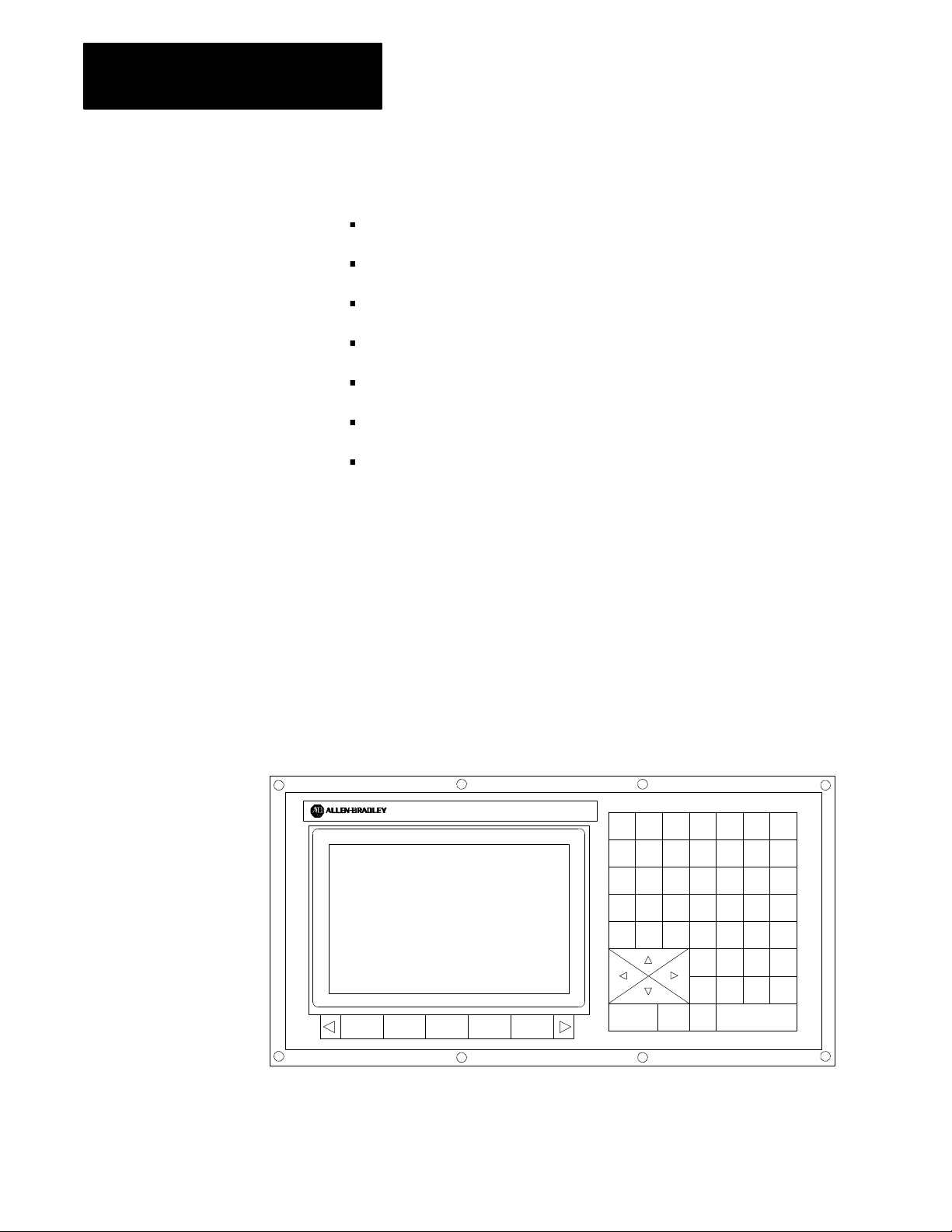
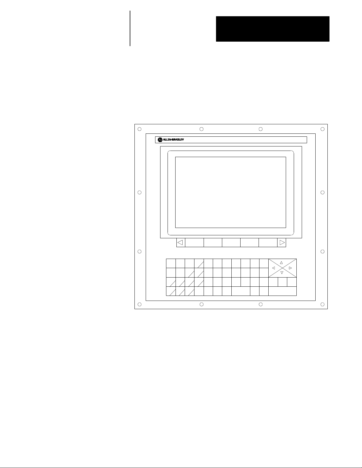
Figure 2.1 shows the monochrome operator panel.
Figure 2.1
Monochrome Operator Panel
9/SE RIES
789ONGP
456XYZQ
123IJKR
_0.ABCL
+
*
SHIFT
;
%
=:FDH
PROC
UVW
SP
E?
MST
CALC DEL CAN RES
DISP
o
]
()[
TRANSMIT
#
EOB
.
19435
2-2
Page 23
Chapter 2
Operating the Control
Figure 2.2 shows the color operator panel. It has keys and softkeys
identical to the monochrome operator panel in a slightly different
configuration.
Figure 2.2
ColorOperatorPanel
9/SERIES
2.1.1
Using the Keyboard
#
H
C
C
T
DISP
,
L
&
SP
DEL
(
EOB
PROC
)
CAN
LINE
TRANSMIT
RES
CNTRL
19436
?
]
.
9
6
5
0:
78
4
123
+
_
=
CALC
N
O
X
P
G
Z
Y
VU
R
Q
I
J
K
D
F
E
B
A
W
S
M
[
SHIFT
Table 2.A lists the functions of keys on the operator panel keyboard. The
names of operator panel keys appear between [ ] symbols.
2-3
Page 24

Chapter 2
Operating the Control
Table 2.A
Key Functions
Key Name Function
Addressand NumericKeys Usethese keystoenter alphabeticand numeric
characters. Ifakey hastwo charactersprinted onit,
pressingit normallyenters theupperleftcharacter.Holding
down the[SHIFT] keywhile pressingitenters thelower
rightcharacter.
CursorKeys ←,↑, →,↓
[SHIFT] and→ or ←
[SHIFT] and↑ or ↓
CalculationKey [CALC] Pressthiskeyto enablea calculator-typefunction onthe
DeleteKey[DEL] Pressthis keyto deletethe characterto theleft ofthe
[SHIFT] and[DEL] Press thiskey todeleteall keyed-indata currently
[CAN] Clearsthe mostcurrently generated,active errormessage.
TransmitKey [TRANSMIT] The dataentered anddisplayed on theinput lines(e.g., a
BlockReset [RESET] This performs a blockreset. Fordetails onBlock Reset,
ControlReset[RESET] +
[SHIFT]
DisplaySelect
[DISP SELECT]
End ofBlock[E.O.B.] Usethis keyto enteranEnd-of-Blockcharacter when
ProcessSelect
[PROC SELECT]
[SHIFT] and[⇒] Pressthe [SHIFT]key while holdingdown the[⇒]
Usethese keystomove thecursor left,right,upand down
in thedata displayarea (lines4-21) of thescreen. These
keysare referredto as theleft,right,up,anddown cursor
keys respectively.
Pressthe rightor leftcursor keyswhileholding downthe
[SHIFT] keyto movethe cursorright andlefton any
line thatdata isbeing inputon(normally screenlines 2-3).
Pressthe up anddown cursorkeys whileholdingdown the
[SHIFT] keyto rollthe displaypageforward or
backward.
control. Basic mathematical expressionscan be evaluated
usingthisfeature. For detailsonCalculator Function,see
page 2-48.
cursoron input lines.
displayedoninput lines.
passwordor a programblock) issent tothe controlwhen
you pressthe[TRANSMIT] key.
seepage2-36.
Pressthe resetkey while holdingdown theshift keyto
performa controlreset. For detailson Control Reset,see
page 2-36.
Usethiskey todisplay thedifferentaxis positiondisplay
softkeys.
editingaprogram orwhen writinganMDI program.
Usethiskey toselect thedifferentprocesses.
softkeyto jumpto theonlinesearch monitorscreen. Press
thesekeys again toreturn tothe previousscreen.
2-4
Page 25
Chapter 2
Operating the Control
2.1.2
Softkeys
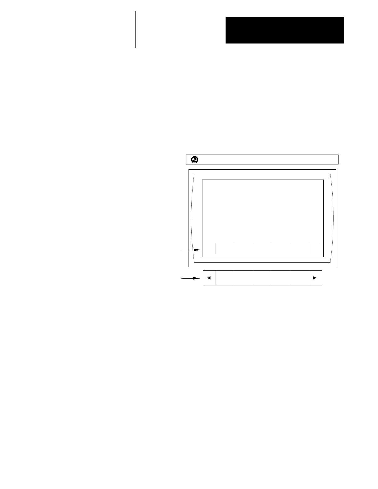
You access the various software features and functions of the control
through softkeys. Softkeys are the row of 7 keys located at the bottom of
the CRT as shown in Figure 2.3. They let you move through the control’s
software. The control displays the function of each softkey on the CRT
directly above the softkey. In this manual, softkey names appear between
the { } symbols.
Figure 2.3
Softkey and Softkey Name Locations
ALLEN-BRADLEY
Softkeynames
displayedhere
9/Series
Softkeys
11978-I
In this manual, we often describe softkeys as being on a certain level, e.g.,
softkey level 3. We use the level of the softkey to determine the location
or necessary path to reach that particular softkey. For example, to get to a
softkey on level 3, you must press a specific softkey on level 1, followed
by a specific softkey on level 2. For a listing of all of the softkeys and
their respective levels, see appendix A.
Softkey level 1 is the initial softkey level the control displays at power-up.
Softkey level 1 always remains the same, and all other levels are
referenced from softkey level 1.
The softkeys on opposite ends of the softkey row have a specific use that
remains standard throughout the different softkey levels. On the left is the
exit softkey displayed with the up arrow {
continue softkey displayed with the right arrow {
↑}, and on the right is the
→}.
2-5
Page 26

Chapter 2
Operating the Control
Use the exit softkey {↑} (on the far left) to regress softkey levels. For
example, if you are currently on softkey level 3 and you press the exit
softkey, the softkeys change to the softkeys previously displayed on
softkey level 2. When you press the exit softkey while holding down the
[SHIFT] key, the softkey display returns to softkey level 1 regardless of the
current softkey level.
When more than 5 softkey functions are available on the same level, the
control activates the continue {
→} softkey at the far right of the softkey
area. When you press the continue softkey, the softkey functions change to
the next set of softkeys available on that level.
Important: When the number of softkey functions on that level does not
exceed 5, the continue softkey is not available.
For example:
(softkey level 1)
PRGRAM
MANAGE
OFFSET MACRO
PARAM
PRGRAM
CHECK
SYSTEM
SUPORT
When you reach softkey level 1, the above set of softkeys appears. Press
the continue softkey {
→} to display the remaining softkey functions on
softkey level 1.
(softkey level 1)
FRONT
PANEL
ERROR
MESAGE
PASSWORD
SWITCH
LANG
On softkey level 1, the control does not display the exit softkey since the
softkeys are already on softkey level 1.
We explain the softkey functions for level 1 and 2 in appendix A, and level
3 or higher in the sections that apply to their specific operations.
To use a softkey function, press the plain, unmarked button directly below
the description of the softkey function.
You can purchase some of the softkey functions as optional features. This
manual assumes that you purchased all available optional features for your
machine. If you did not purchase an option, the softkey is blank.
2-6
Some features accessed through a softkey can be password protected.
When a feature is password protected, the softkey that accesses that feature
is no longer displayed.
Page 27

Chapter 2
Operating the Control
2.1.3
Using the CRT
Your control has one of these monitors:
9-inch monochrome monitor
19435
12-inch color m onitor
19436
Both have identical displays and graphics capabilities.
Certain lines of the screen are dedicated to displaying specific information:
Line Area Content
1 machine/system
message
2-3 inputlines When datais enteredusingthe keyboard,the controldisplays the
4-20 data display The controldisplays axisposition data,listing ofthe partprogram,
21 -22 PALmessage The controldisplays anymessages generatedby thecontrol’s PAL
23 -25 softkeydisplay Thecontrol displaysthe currentlyavailable softkeyfunctionsinthis
Ifan error occursor amessage isgenerated foranyreason during
machineoperation orprogramexecution,the controldisplays the
corresponding machine/systemmessage inthis area. Only the
highestpriority,most currentmessage isdisplayed here.
enteredcharacters onthese linesuntilyou pressthe
[TRANSMIT] key. Somescreens canhave onlyline 2 asan
inputline.
wheel lengthoffsetdata, G/M/H/T/F/S/D codes,graphics, and
otherdata in thisarea asdetermined bythe selecteddisplay.
programin this area.
area.
2-7
Page 28
Chapter 2
Operating the Control
2.2
The MTB Panel
Figure 2.4 shows the MTB panel. Table 2.B lists the selections on this
panel. Your system may contain optional or custom MTB panels different
than the one shown below. See the documentation prepared by your
system installer for details.
We show selection names on the MTB panel between the < > symbols
when referred to in this manual. Most selections on the MTB panel are
configured by your system installer’s PAL program. This manual assumes
that PAL has been written as intended for normal operation. If a selection
does not work the way it is described i n this manual, see documentation
preparedby your system installer.
Figure 2.4
Push-Button MTB Panel
MODE SELECT SPEED/MULTIPLY
MDI MAN
AUTO
CYCLE
START
SINGLE
BLOCK
CYCLE
STOP
JOG SELECT
CONT
INCR
HOME
HAND
AXIS
+4
+X
+Y TRVRS --Y
+Z --4
LOWX1MEDL
MEDH
X1000
FUNCTION
-- X
-- Z
F1
F3 F4
F5
SPINDLE SPEED
OVERRIDE
MED
X10
X100
HIGH
X10000
FEEDRATE
F2
F6
OVERRIDE
50
0
%
100
150
SPINDLE
DIRECTION
CCW CW
OFF
RAPID FEEDRATE
OVERRIDE
F1 25
50
OFF
ESTOP
RESET
EMERGENCY
STOP
100
ON
2-8
Page 29

Chapter 2
Selectstheoperationmode
Operating the Control
Table 2.B
Selections on the MTB Panel and How They Work
Switch orButton Name
MODE SELECT
JOG SELECT Selectsthe jogmethod to beactive inmanual mode
SPEED/MULTIPLY Selects an axisfeedrateoraxis feedamount multiplicationratio usedin themanual mode. Each
How It Works = Default forPush-ButtonMTB Panel
AUTO ---- automaticmode
MANUAL ---- manual mode
MDI ---- manual datainput mode
HANDWHEEL ---- HPG (handpulse generator)jog
INCREMENTAL ---- incrementaljog
CONTINUOUS ---- continuous jog
HOME -- -- m ac hi ne h om e
selectionmodifies theactive feedrateby avalue setinAMP. Modificationalsodepends onthe setting
of<JOGSELECT> asdescribed below:
• HANDWHEEL
When inhandwheel jog mode,SPEED/MULTIPLYalters thehandwheel resolution bya factor
determined in AMP. Yoursystem installer sets thevaluefor:
-LOWX1
-MEDLX10
-MEDL X100
You cannotuse the valueslisted belowfor handwheeljog:
-MEDH X1000
-HIGHX10000
• INCREMENTAL
When inincremental jog mode,SPEED/MULTIPLYalters theincremental jog distance
in AMPbyyour system installer. Your systeminstallersetsa value fortheselections. The
incrementaljog speed
<FEEDRATE OVERRIDE>.
• CONTINUOUS
When incontinuous jog mode,SPEED/MULTIPLYacts asa feedrate selectionswitch whichhas
values setinAMP by yoursysteminstaller. Your systeminstallersetsa value forall5 selections
independentlyfor eachaxis. <FEEDRATE OVERRIDE> can beusedfor speedadjustments.
isfixed to mediumbut canstill becontrolled by
byafactor set
Important: The values for thediff erent<SPEED/MULTIPLY> selections areconfigured byyour
system installer.
2-9
Page 30

Chapter 2
Operating the Control
Table 2.B
Selections on the MTB Panel and How They Work (continued)
Switch orButton Name
SPINDLE SPEEDOVERRIDE Selectsthe overridefor programmedspindle speedsin5% incrementswithin arange of50%to 120%.
SPINDLE or
SPINDLE DIRECTION
FEEDRATEOVERRIDE Selectsafeedrateoverride percentagefor thefeedrate programmedwith an Fword in anyof the
RAPIDFEEDRATEOVERRIDE Selectsthe override forrapid feedrates. Select fromF1, 25%,50%, and 100%where F1 isa rapid
EMERGENCY STOP This button stopsmachine operationanddisables thespindle andaxisdrives whenpressed.
E-STOP RESET This button resetsan emergencystop conditionwhenpressed. Beforepressing thisbutton the
CYCLESTART The controlbegins orresumes partprogram execution,MDI programexecution,orprogram check
CYCLESTOP Thecontrol stopspart programexecution, MDIexecution,orprogram checkwhen thisbutton is
SINGLE BLOCK The controlexecutesorchecks oneblock ofa part programor MDIentry eachtime the
AXIS/DIRECTION Thesebuttons areused formanual operations. They selectanaxis anddirection when<JOG
TRVRS Hold thisbuttondownwhile executinga continuousjog move tooverride theactive feedrateand jogan
F1-F4 The functionsfor thesebuttons areassignedby thesystem installer. Refer tothe documentation
JOG RETRACT Usejogretracttojog acutting toolawayfromtheworkpiece duringautomaticorMDI program
BLOCK RETRACE To retrace thetool pathin a partprogram already executed(up to15blocks), press thisbutton.
ON Turnson power tothe control.
OFF Turns offpower tothe control.
Selectsspindle rotation,clockwise (CW),spindle stop(OFF), counterclockwise (CCW). Can be
overriddenbyany programmedspindle directioncommand.
feedratesmodes (G93/G94/G95)and thereciprocation feedrateprogrammed withan E word.
<FEEDRATE OVERRIDE> has arange of 0%to 150%ofthe programmed feedrateandalters the
programmedfeedrate in10% increments. When setto 0%, thecontrol iseffectivelyin feedhold.
feedrateoverridesetting establishedinAMP bythe system installer.
conditionthat causedthe E-Stopshould be resolved.
when thisbuttonispressed.
pressed. Ifpressed during theexecution of aprogram block acycle suspend stateoccurs.
<CYCLE START> buttonis pressedwhen single blockis active.
SELECT>isset forcontinuous,i ncremental, orhome. If <JOGSELECT> issetforhandwheel,these
buttonsselect anaxis only. Directionisthen determinedby handwheelrotation.
axisinrapid traverse.
prepared bythe systeminstaller for details.
execution.The controlcanretracethe jog movesand returnthe cuttingtool automaticallyto the
workpieceby pressing<CYCLE START>. Refer tochapter 7for moreonthis.
= Default forPush-ButtonMTB PanelHow ItWorks
2-10
Important: You can disable m any of the override switch settings by
programming the correctM code or by setting a particular paramacro
parameter. See their respective sections for details on these features.
Page 31

Chapter 2
Operating the Control
2.3
SoftwareMTB Panel
{FRONT PANEL}
The 9/Series control offers a software MTB panel that performs many of
the functions of an MTB panel. This feature uses softkeys instead of the
normal switches and buttons of a panel. If your control uses a standard
MTB panel (described on page 2-8) or some other custom MTB panel,
the requests for operations from the panel take priority. This means that
requests from the software MTB panel are ignored if a request from a
standard or custom MTB panel is sent.
The software MTB panel’s operation depends on PAL, especially if the
control uses either a standard or custom MTB panel. See the
documentation prepared by your system installer for details about using the
software MTB panel. Your system installer uses PALto disable the
{FRONT PANEL} softkey.
The software MTB panel controls these features:
Feature Function
ModeSelect Selectseither AUTO,MDI, orMANUAL modesas thecurrent operatingmode ofthe control.
Rapid Traverse Replaces thefeedrate whenexecuting acontinuous jog movewith therapid feedrate.
FeedrateOverride Selectsa feedrateoverride percentagefor thefeedrate programmedwith anFword in anyof thefeedrates modes
(G93/G94/G95)and the reciprocation feedrateprogrammed withan E word. This switchhas a rangeof 0%to
150% ofthe programmedfeedrateandalters theprogrammed feedratein 10%increments. When setto 0%,the
controlis effectively in feedhold.
Rapid FeedrateOverride Selectsthe overridefor rapidfeedrates. Select fromF1, 25%,50%, and100%,where F1is a rapidfeedrate
override setting established in AMPby your systeminstaller.
SpindleDirection Selectsspindle rotation,clockwise (CW),spindle stop(OFF), orcounterclockwise (CCW). The frontpanel is
overriddenbyany programmedspindle directioncommand.
SpindleSpeedOverride Selectsthe overridefor programmedspindle speedsin 5% increments withinarange of50% to120%.
DryRunMode Placescontrolindry runmode. This replacesfeedrates withthe dryrunfeedrates. See page7-21for details.
BlockDelete Allowsactivationofthe blockdelete feature“/ or/1”. Blockdelete 2 -9 are notavailable withthe
{FRONT PANEL}. See page7-2 fordetails.
M-FunctionLock Allowsselect M-,S-, T-, and B-codesto beignored. See page7-2 fordetails.
Optional Stop Enables ordisablesthe M01optional stopcode. When thisfeature is“ON,” an M01in a partprogram stops
automaticexecution. When thisfeatureis“OFF,”an M01ina partprogram isignored. Seepage10-31 fordetails
on M01.
SingleBlock Causes thecontrol toexecute orcheck oneblockof apart programor MDIentry eachtime you pressthe
<CYCLE START> buttonwhen thisfeature ison.
WARNING:Single blockexecution isnot possibleduring reciprocation.
Mirror Image Mirrorsthe axiscommands in thepart programaround theselected axis. See page12-79for details.
AxisInhibit Preventsaxis commandsfrombeingexecuted. The controlsimulatesaxismotiononinhibited axesusing Acc/Dec
and feedrates; however, noactual axis motionfor theinhibited axesis generated. See page 7-20for details.
(continued on next page)
2-11
Page 32

Chapter 2
Operating the Control
The software MTB panel controls these features: (continued)
Feature Function
JogtheAxes Allows manualmotions tobe performedin any oneof thejoggingmodes. You cannotperform multi-axisjogs using
thesoftware frontpanel feature. See page4-2for details.
Set Zero Changesthe wheel’scurrentposition inthe work coordinatesystem to0 for theselected axis. This isdone by
shiftingthe work coordinatesystem. See page12-89 fordetails.
BlockRetrace Allows up to15 partprogram blocksto be retraced during programexecutionandallow thewheelto automatically
re-executetheseblocks. See page 7-30for details.
Jog Retract Allowsthe wheel tobe manuallyjoggedaway fromthe partand thenautomatically returnsthe wheelto thepartby
retracingthe joggedmoves. Up to15jog movescan be remembered. See page 7-27for details.
Cycle Start The control beginsor resumespart programexecution, MDIprogram execution, or programcheck whenyou press
thisbutton.
Cycle Stop Thecontrol stopspart programexecution orprogram checkwhen youpressthisbutton. If pressedduring the
execution ofa programblock,a cycle suspendstate occurs.
WARNING:During reciprocation, pressing<CYCLE STOP>does notnecessarily stopthe reciprocatingaxis.
Software MTB Panel Screen
Use the software MTB panel screen to specify the status of the MTB
features. To access the software MTB panel screen:
1. From the main menu screen, press the
(softkey level 1)
PRGRAM
MANAGE
FRONT
PANEL
OFFSET MACRO
PARAM
ERROR
MESAGE
PASSWORD
You see the software front panel screen displaying the current status
of the alterable features:
{FRONT PANEL} softkey.
PRGRAM
CHECK
SYSTEM
SUPORT
SWITCH
LANG
2-12
Page 33

Chapter 2
Operating the Control
SOFTWARE FRONT PANEL
MODE SELECT: MDI
RAPID TRAVERSE: OFF
FEEDRATE OVR: 0%
RAPID FEEDRATE OVR: 0%
SPINDLE DIRECTION: OFF
SPINDLE SPEED OVR: 50%
DRY RUN MODE: OFF
BLOCK DELETE: OFF
M-FUNC LOCK: OFF
OPTIONAL STOP: OFF
SINGLE BLOCK: OFF
MIRROR IMAGE: X
AXIS INHIBIT: XZ
USE CURSOR FOR SELECTION
JOG
AXIS
PRGRAM
EXEC
2. Press the up and down cursor keys to selectthe feature to change.
The value of the selected feature appears in reverse video.
3. Pressthe left and right cursor keys to alter the value of the selected
feature.
When you select the mirror image and axis inhibit features, the softkey
names change to the axis names. Press the softkey that corresponds to
the axis (or axes) to which you want to assign these features.
2-13
Page 34

Chapter 2
Operating the Control
Jog Axis Screen
After accessing the software front panel screen and selecting the various
features for your application, you can use the jog axis screen to:
jog the axes of the control
shift the current work coordinate system to force the current wheel
position to be the zero point of the work coordinate system
To jog the axes of the control:
1. Press the
{JOG AXIS} softkey. The {JOG AXIS} softkey is only
available when mirror image or axis inhibit are not in reversevideo.
If one these features is in reverse video, press the up cursor key.
(softkey level 2)
JOG
AXIS
PRGRAM
EXEC
You see the jog axis screen:
PROGRAM [INCH] F 0.000 MMPM
R X 0.000 S 0.0
Z 0.000 T 0
FILENAME
SUB NAME
MEMORY MAN STOP
E-STOP
2-14
AXIS SELECT: X
JOG SELECT: CONTINUOUS
SPEED/MULTIPLY LOW
HPG NUMBER 0
SET
ZERO
JOG
AXIS +
JOG
AXIS -
Page 35

Chapter 2
Operating the Control
You can select the:
axis to jog
type of jog
speed multiply value (see manual operating mode on page 4-1)
HPG number (if HPG has been selected as the type of jog)
2. Use the up and down cursor keys to select a parameter and the left
and right cursor keys to alter the value assigned to that parameter.
3. Jog the selected axis in the selected direction by:
If jog type is: Then:
NotHPG pressthe softkeythat correspondsto thedirection onthe
selectedaxis tojog
HPG the directionof HPGrotation determinesthe directionto jog
See page 4-2 for details on jogging an axis.
Set Zero
If you want to shift the current work coordinate system to force the current
wheel position to be the zero point of the work coordinate system, press
the
{SET ZERO} softkey.
The current axis position becomes the zero point of the currently active
work coordinate system.
{SET ZERO} softkey does not function when the control is in
The
handwheel mode. See page 11-18for details on set zero operations.
ProgramExecute Screen
After accessing the software front panel screen and selecting the various
features for your application, you can use the program execute screen to
perform a:
block retrace
jog retract
cycle start
cycle stop
Important: Before you press the {PRGRAM EXEC} softkey, you should
have selected a program for automatic execution as described on page 7-6.
2-15
Page 36

Chapter 2
Operating the Control
To perform one of these options:
1. Press the {PRGRAM EXEC} softkey.
(softkey level 2)
JOG
AXIS
PRGRAM
EXEC
You see the program execute screen:
PROGRAM [ MM ] F 0.000 MMPM
R X 0.000 S 0.0
Z 0.000 T 0
MEMORY MAN STOP
E-STOP
FILENAME
SUB NAME
2-16
BLOCK
RETRCE
JOG
RETRCT
CYCLE
START
CYCLE
STOP
Page 37

Chapter 2
Operating the Control
2. Press the softkey that corresponds to the selected option.
Toperform
thisoperation: Press:
Cycle Startor
Cycle Stop
BlockRetrace the {BLOCKRETRCE} softkey; eachtime you pressthe {BLOCK
Jog Retract the {JOGRETRCT}softkey. This callsup thejog retractscreen. Select
thesoftkey thatcorresponds tothe desiredfeature. Detailsonthese
featuresare describedearlier in thischapter.
RETRCE}softkey thecontrol automaticallyretracesthe previously
executedblock. Pressing {CYCLESTART}returns thewheel tothe
startpoint ofblock retrace. Details onblock retracecan be foundin
chapter7.
(softkey level 3)
BLOCK
RETRCE
theaxis, typeof jog,speedmultiply value(see page4-1 ),andHPG
number(ifHPG hasbeen selectedas the typeof jog)by usingtheup
and downcursor keysto selectthe function,and theleft andrightcursor
keysto alterthe value assignedto thatfunction.
(softkey level 3)
BLOCK
RETRCE
the {JOG AXES+}or {JOG AXES--}softkeys to select thedirection tojog
theaxis. Press theexit {
The grindingwheel automaticallyretraces thejog movesmade when
the{CYCLE START} softkeyis pressed. Details onjog retractcan be
foundinchapter 7.
(softkey level 4)
JOG
RETRCT
JOG
RETRCT
CYCLE
START
CYCLE
START
CYCLE
STOP
CYCLE
STOP
↑}softkey whenthe jog retractis complete.
JOG
AXES+
JOG
AXES-
2-17
Page 38

Chapter 2
Operating the Control
2.4
Powering the Control
2.4.1
TurningOnPower
This section describes the procedures for turning on and off power to the
control. See the documentation prepared by your system installer for more
specific procedures.
Follow this procedure to turn on power to the control:
1. Visually make sure that the control and the machine are in normal
operating condition.
2. Press the power <ON> button.
Important: Do not touch any other buttons after you press the power
<ON> button until characters appear and remain on the screen.
3. Make sure that characters appear on the screen within approximately
10 seconds.
Important: If, after you press the power <ON> button, the screen does not
display characters within a reasonable warm up period (about 10 seconds),
immediately press the power <OFF> button and contact service personnel.
2-18
Page 39

Chapter 2
Operating the Control
After power has been turned on, the control displays the power turn-on
screen. To activate the main menu, press the
[TRANSMIT] key.
You see the main menu screen:
E-STOP
PROGRAM [ MM ] F 00000.000 MMPM
R X 00000.000 S
Z 00000.000 T 12345
FILENAME
SUB NAME 9999
MEMORY MDI STOP
(PAL messages)
PRGRAM
MANAGE
OFFSET MACRO
PARAM
PRGRAM
CHECK
SYSTEM
SUPORT
The softkeys available on the main menu screen are referred to as “level 1”
softkey functions. Some of the softkey functions are purchased as optional
and may not appear exactly as shown.
2-19
Page 40

Chapter 2
Operating the Control
2.4.2
Turning Off Power
2.5
Control Conditions at
Power-Up
Turnoff power to the control when it i s not used for an extended period of
time.
To turn off power to the control:
ATTENTION: To prevent damage to the machine, never turn
off power while a part program is being executed. Before
turning off power, makesure that the control is in CYCLE
STOP.
1. Press the
2. Make sure that power is turned off to all peripheral devices (tape
reader, tape punch, etc.) that are connected to the control.
3. Press the power <OFF> button.
The control assumes a number of initial operating conditions at power-up
or at a control reset operation (see page 2-18). These are:
Initial Password Access is to the level that was active when power was
turned off (provided that level is a power-up level selected in access
control). If the active level when power is turned off is not a power-up
level, the control defaults to the next lower level that is a power-up level
(see page 2-23 on access control).
<EMERGENCY STOP> button.
2-20
The control is placed in E-Stop. The control is not allowed to come out
of E-Stop if the default AMP is loadedat power-up, or if there is no
PAL program loaded in your system. If either of these is the case, an
appropriateerror message occurs.
Page 41

Chapter 2
Operating the Control
The control defaults to one G-code from each of these groups (as set in
AMP):
ModalGroup: G-code:
1 G00 Rapidtraverse
G01 Linear interpolation
2 G17 Plane Selected
G18 Plane Selected
G19 Plane Selected
3 G90 Absolute
G91 Incremental
4 G22 ProgrammableZ one 2 and3(On)
G22.1 ProgrammableZone2 (Off)3 (On)
G23 Programmable Zone2 and 3(Off)
G23.1 ProgrammableZone2 (On)3(Off)
5 G94 Feed perminute
G95 Feed per revolution
6* G70 Inch mode
G71 Metric mode
12 G54 -G59.3 work coordinate system
13 G61 ExactStop Mode
G62 Auto CornerO verride Mode
G64 Cutting Mode
15** G15 AngledWheel TransformOff
G16.3 Angled WheelNormal Motion
G16.4 Angled Wheel2 Step Motion
17 G96 CSSOn
G97 CSSOff
18 G07 RadiusProgramming Mode
G08 Diameter ProgrammingMode
20 G39 Wheel/RadiusComp Linear
G39.1 Wheel/Radius CompRounding
22 G36 ShortBlock Feed Clamped
G36.1 ShortBlock Full Feed
* This Gcode group isonly establishedat powerup. A control reset
will notchange thelast programmedstate ofthis modalG code group.
** Only availableon cylindricalgrinders
To show the current operating conditions at any time, access the G-code
status screen as described on page 9-2. If this is done immediately after
power-up, it shows the initial operating conditions selected in AMP along
with other control power-up default conditions.
2-21
Page 42

Chapter 2
Operating the Control
2.6
Emergency Stop Operations
Press the red <EMERGENCY STOP> button on the MTB panel (or any other
E-Stop switches installed on your machine)to stop operations regardlessof
the condition of the control and the machine.
ATTENTION: To avoid damage to equipment or hazard to
personnel, your system installer should connect the
button so that pressing the button opens the circuit
STOP>
<EMERGENCY
connected to the E-STOP STATUS terminal on the control’s
subprocessor board. This disables the axis drives and the
spindle drive circuits, provided both are connected to this
terminal. See your integration manual or the documentation
preparedby your system installer for details.
If equipped with the standard MTB panel, the following occurs
automaticallyafterpressing the
<EMERGENCY STOP> button:
the control displays “E-STOP” in the message area. This indicates that
the control is i n the emergencystop state
the red light in the <CYCLE STOP> button lights up to indicate that the
control is in the feedhold state
2.6.1
EmergencyStop Reset
power to all axis drive motors is turned off
Important: If you press the
<EMERGENCY STOP> button while a part
program is running, program execution can be resumed at the point of
interruption. See the mid-program start feature described in chapter 7.
After the control has entered the emergency stop state, you must perform
an E-Stop reset before program execution can continue.
ATTENTION: Before resetting the emergency stop state, first
locate and eliminate the cause of the emergency stop.
<EMERGENCY STOP> button is locked in the pressed position, it must
If the
be released before the emergency stop state can be reset. You can release
the locked button in different ways depending on its type. With the
standard MTB panel, turn the button clockwise until it pops out.
2-22
Page 43

Chapter 2
Operating the Control
To reset the emergency stop state, press the <E-STOP RESET> button. Once
you push the E--Stop Reset button to clear the E--S top state, the message,
“RESETTING E--STOP”displays to alert you that the control is attempting
to come out of E--Stop. After the cause of the E--Stop is resolved, the
control clears the “E--STOP”message. If the error condition is not cleared,
the “RESETTING E--STOP” message clears, but the “E--STOP”message
continues to flash as the control remains in E--Stop state.
If the E-Stop occurred during program execution, the control resets the
program when you perform an E-Stop reset (provided AMP is configured
to perform a control reset or E-Stop reset). Assuming that you perform a
control reset, program execution begins from the 1st block of the program
when you press
<CYCLE START>. If the current axis position prohibits this,
the operator can manually jog the axes clear, or consider executing a
mid-program start (see page 7-13). If you do not perform a control reset or
E-Stop reset, the control aborts the remainder of the program block being
executed when E-Stop took place, and a
<CYCLE START> begins program
execution at the next block.
2.7
Access Control
Important: If you do not eliminate the cause of the E-Stop, the circuit
connected to the E-STOP STATUS terminals on the sub-basic board
remains open, and the emergencystop state is not reset even when you
press the
<E-STOP RESET> button.
Reciprocationstops when an emergency stop condition occurs. No motion
occurs when the emergencystop is reset. If your control’s AMP is
configured such that the control is not
reset after an E-Stop reset, then
typically reciprocation resumes with the next cycle start. This allows part
programs to be resumed immediately without having to first restart
reciprocation. For details, see the documentation prepared by your system
installer.
Access control lets your system installer assign different functions of the
control to different users by means of a password. See page 2-28 for a list
of the functions that can be protected on the control.
Each protectable function is assigned an access level that is made active
when the operator enters his password. When an access level is made
active, all functions that are assigned to that access level become available.
Access levels range between 1 and 8 where 1 is the highest level and 8 is
the lowest. A different password is assigned to each of the different access
levels. You can assign a total of 8 passwords.
Important: If you do not want to use password protection, select all
functions as accessible for access level 8. Since access level 8 is
automatically available at power-up, no password is necessary to access
any of the functions of the control. You can also disable password
2-23
Page 44

Chapter 2
Operating the Control
protection by assigning a level as the power-uplevel using the
“POWER-UP LEVEL” parameter as described on page 2-29.
2.7.1
Assigning Access Levels
and Passwords
This section shows you how to:
set the functions assigned to a particular access level
change the functions assigned to a particular access level
change the password used to activate that access level
Important: You can only assign functions or passwords to another access
level if:
The user attempting to make the change has a higher access level
than the access level he is attempting to change. This means that
if a user’s password is assigned to access level 6, that user can
change only the functions or passwords for access levels 7 and 8.
Functions, or a password, cannot be assigned to access level 6 with
a level 6 password
Functions that are not available to the current user cannot be
assigned to other levels. If a user with access level 6 is changing a
lower-access level’s functions, access level 6 must have access to
any functions that are changed. For example, if an access level 6
user does not have access to
or remove
{SYSTEM SUPORT} from access level 7
{SYSTEM SUPORT}, he cannot assign
2-24
The current user’s password must allow access to the
{ACCESS CONTRL} function
To change the functions or password of a lower user number, follow these
steps:
1. Press the
(softkey level 1)
{PASSWORD} softkey.
PRGRAM
MANAGE
FRONT
PANEL
OFFSET MACRO
ERROR
MESAGE
PARAM
PASSWORD
PRGRAM
CHECK
SWITCH
LANG
SYSTEM
SUPORT
If the {ACCESS CONTRL} softkey does not appear on the screen, the
currently active access level is not allowed to use the
Page 45

Chapter 2
Operating the Control
{ACCESS CONTRL}
{ACCESS CONTRL}.
2. Press the
{ACCESS CONTRL} softkey. This displays the access control
screen (Figure 2.5).
(softkey level 2)
Figure 2.5
Access Control Screen
PASSWORD NAME -- (current password)
1 ACTIVE PROGRAM 18 ACCESS CONTROL
2 PROGRAM MANAGE 19 SWITCH LANGUAGE
3 EDIT PROGRAM 20 POWER UP LEVEL
4 COPY PROGRAM 21 TIME PARTS
5 RENAME PROGRAM 22 SI/OEM MESSAGE
6 DELETE PROGRAM 23 SCALING
7 REFORMAT MEMORY 24 CHANGE DIRECTORY
8 OFFSETS 25 AUX COMM
9 TOOL WEAR 26 SEARCH MONITOR
10 TOOL GEOMETRY 27
11 ACTIVE OFFSET 28
12 BACKUP OFFSET 29
13 QUICK CHECK 30
14 SYSTEM SUPPORT 31
15 PRGRAM PARAMET 32
16 AMP 33
17 PARAMACRO PROG 34
function. Enter a password that has access to
ACCESS
CONTRL
UPDATE
01 02 03 04
& EXIT
The softkey names change to display the 8 access levels and their
corresponding passwords (provided that a password has been
assigned to that access level). Only the password names of access
levels that are lower than the currently active access level appear.
2-25
Page 46

Chapter 2
Operating the Control
3. Press the softkey that corresponds to the access level for which you
want to assign access to functions. The pressed softkey appears in
reverse video. The password name assigned to that access level is
moved to the “PASSWORD NAME.”
(softkey level 3)
UPDATE
& EXIT01(NAME)02(NAME)03(NAME)04(NAME)
UPDATE
& EXIT05(NAME)06(NAME)07(NAME)08(NAME)
STORE
BACKUP
Important: If you want to change the functions available to an
access level that is equal to or higher than the current user’ s access
level, the error message “ACCESS TO THIS LEVEL IS NOT
ALLOWED” appears. A user cannot change the features that are
assigned to his current access level or any level that is higher than his
own.
4. Ifyou want to:
a. enter or change the password (NAME) for the selected level,
edit the password (NAME) next to the “PASSWORD NAME”
prompt by using the input cursor as described on page 2-41.
b. change the functions for this password, move on to step 5.
c. save the change made to the password and leave the access
control screen, press the {UPDATE & EXIT} softkey.
Functions that are currently available to the selected level appear in
reverse video on the access level screen.
5. Usethe up, down, right, and left cursor keys to select the functions to
change for that access level. The selected function appears with a
flashing > to the left of the function.
2-26
6. Press the
[TRANSMIT] key to toggle the function between accessible
and inaccessible for that access level.
Page 47

Chapter 2
Operating the Control
Important: If you want to activate or deactivate a function that is not
accessible to the current user’s access level, the message “ACCESS TO
THIS FUNCTION NOT ALLOWED” appears. Only features that are
accessible to the current user’s access level can be selected as accessible or
inaccessible to a lower user’s access level.
7. Press the {UPDATE & EXIT} softkey to store the changes made to
accessible functions for the user levels and return the control to
softkey level 1.
(softkey level 3)
UPDATE
& EXIT01(NAME)02(NAME)03(NAME)04(NAME)
UPDATE
& EXIT05(NAME)06(NAME)07(NAME)08(NAME)
2.7.2
PasswordProtectable
Functions
STORE
BACKUP
This section describes the functions on the control that can be protected
from an operator by the use of a password. If a user has access to a
function, the parameter associated with that function appears in reverse
video on the access control screen (see Figure 2.5).
You control access to the functions in Table 2.C by using passwords.
Table 2.C describes the function that is enabled (the operator can perform
them) if the parameter name appears in reverse video. If the function does
not appear in reverse video, the function is protected and cannot be
accessed by the operator.
Some parameters enable more than one function. If a parameterthat
enables multiple functions is not selected as accessible, some of the
functions that would be enabled by the parameter can be enabled
individually by using other parameters.
2-27
Page 48

Chapter 2
Operating the Control
Parameter Name Function becomesaccessible whenparameter name appearsin reversevideo:
1) ACTIVEPROGRAM To accessthese features,both ACTIVEPROGRAM andPROGRAMMANAGE (number2 below)must be
2) PROGRAM MANAGE • {ACTIVE PRGRAM}— All ofthe functionsin 1 aboveprovided ACTIVEPROGRAM (number1
3) EDITPROGRAM {EDIT PRGRAM}— Editan existing programor createa newprogram.
4) COPYPROGRAM {COPYPRGRAM} —Copya programto orfrom memoryor storagedevice.
5)RENAME PROGRAM {RENAMEPRGRAM} —Rename a programname.
6)DELETEPROGRAM {DELETE PRGRAM}— Deletea singleprogramstoredinmemory.
7)REFORMMEMORY {REFORM MEMORY} — Deleteall programscurrently storedin memoryand formatRAM.
8) OFFSETS • {WORK CO-ORD} —Displayandalterthe preset work coordinate systemzero locations and the fixture
9)RADIUS TABLE
10) WHEEL GEOMETRY {WHEEL GEOMET}— Displayandalter thewheel geometry, radiusand orientationvalues.
11)ACTIVEOFFSET {ACTIVE OFFSET}— Change thecurrently active offsetnumber withoutrequiring theprogramming ofa
12) BACKUPOFFSET {BACKUPOFFSET}— Makea copy ofthe currentwheel offset data.
13)QUICKCHECK™
14) SYSTEMSUPORT • {PRGRAMPARAM}— Displayand change thetables forprogrammable zones1 and2,the singledigit
Table 2.C
Password Protectable Functions
assignedto the user.
• {SELECT PRGRAM}— Selecta programforautomaticoperation.
• {SEARCH}— Searcha partprogram foracharacterstring orsequencenumber tobegin program
executionat.
• {MID ST PRGRAM} —Startprogram executionfrom somelocation otherthan thebeginningand
stillset all ofthe parameterspreviouslydefined in theprogram active.
• {T PATH GRAPH} —Enable theactive graphicsfeature.
• {CANCEL PRGRAM}— Disablethecurrentlyactive programfrom execution.
• {SEQ STOP}— Chooseasequence numberfor automaticprogram executionto stopat.
above)isalso selected.
• {EDIT PRGRAM}— Editanexisting programor createa new program.
• {DISPLYPRGRAM} —Display a programusing thedisplay function.
• {COPYPRGRAM}—Copy aprogram toorfrommemory.
• {VERIFY PRGRAM}— Verify thattwo programsare identicalusingthe verifyfunction.
• {COMENT} — Addcommentstoa programname inthedirectory.
• {RENAME PRGRAM}— Changeaprogram name.
• {DELETE PRGRAM}— Deleteasingle programstored inmemory.
• {REFORM MEMORY}— Deleteallprograms currently storedin memory.
offsetvalue.
• {WHEEL GEOMET}—Display andalter thewheelgeometrytables.
• {RADIUS TABLE} —Displayand alterthe dresser/wheelradius andorientations.
• {ACTIVE OFFSET} —Change thecurrently activeoffsetnumber withoutrequiring theprogramming ofa
differentoffsetnumber.
• {COORDROTATE} —Rotateallof the work coordinate systemsfrom the machine coordinate system.
• {BACKUP OFFSET}—Make acopy ofthe currenttool offsetdata.
differentoffsetnumber.
{QUICKCHECK} —Usethe syntaxand formatchecker orthe {QUICK CHECK}with graphicsfunction.
feedrates,and the fixedcycle operating parameters.
• {AMP} —Change any ofthe onlineAMP features.
• {DEVICE SETUP}— Displayand change anyof thecommunication parametersfor theperipheral
devices.
• {MONI-TOR} —Display thecurrent I/Oconfigurations andthe axismonitor forfollowing error, distance
to marker,etc.
2-28
Page 49

Chapter 2
Operating the Control
Table 2.C
Password Protectable Functions (continued)
Parameter Name Function becomesaccessible whenparameter name appearsin reversevideo:
15) PRGRAM
PARAMETERS
16)ONLINEAMP {AMP}—Display andchange theonlineadjustable machineparameters.
17)PARAMACRO™ PARAM
18)ACCESS CONTROL {ACCESS CONTRL}—Assigndifferent functions todifferent accesslevels,changethe current
19)SWITCHLANGUAGE {SWITCH LANG.}— Changethecurrentdisplaysfromonelanguage toanother.
20) POWER-UP LEVEL WhenPOWER-UPLEVEL is showninreverse video,itindicates thatif poweristurned offwhen thislevel
21)TIMEPARTS • {SET TIME} —Change or resettimeparameters
22) SI/OEMMESSAGE • {ENTERMESSAGE} — Entera new messageto bedisplayedon the control’spower-up screen.
23) SCALING When SCALING is notin reversevideo, theoperator stillhas accessto the {SCALNG}softkey;however
24)CHANGEDIRECTORY {CHANGE DIR}— Displayeitherthe mainpart programdirectoryorthe protectablepart programdirectory.
25)AUXCOMM Allows accessto the{AUX COMM}softkeythatsetsData Highway Communication Module Parameters.
26)SEARCH MONITOR Allowsaccess tothe{SEARCHMONITOR} softkeythat allowssearching andmonitoring ofthe control’s
27) P ASSTHRU ENABLE Allows accessto the{PT ENABLE}softkey thatenables remoteI/O passthru ofAMP, PAL, and otherODS
{PRGRAMPARAM}— Displayandchange thetables forprogrammable zones1 and 2,the singledigit
feedrates,and the fixedcycle operating parameters.
{MACROPARAM}— Displayorchange anyof thevaluesin theparamacro tableswithout using
programmingcommands.
password,or viewthefunctionsassigned to thedifferentaccess levels.
isactive, thislevel automaticallybecomes activewhen poweristurned backon. Ifthisis notin reverse
video,itindicatesthat thecontrol defaultsto level8access control at nextpower-up.
• {SET DATE}— Change orreset dateparameters
When TIMEPARTS is notin reversevideo, theoperator canonlyperformthe following functions on the
timeand parts screen:RUN TIME,CYCLE TIME, and LOTSIZE.
• {STORE BACKUP}— Storean enteredmessage forthe power-up screento Backupmemory.
valuesonthe screencannot bemodified.
PALprogram.
features. The {PTENABLE} softkeyis onlyavailable whenAMP is configured to disallowblock transfers
and thesystem containsremote I/Ohardware thathasbeen enabledthroughPAL.
2.7.3
StoringPasswordListto
Backup Memory
You can save your password list in the backup memory of the control so
that it won’t be lost if system power and battery-backup fails.
To store the password list, follow these steps:
1. Press the
(softkey level 1)
{PASSWORD} softkey.
PRGRAM
OFFSET MACRO
MANAGE
FRONT
PANEL
ERROR
MESAGE
PARAM
PASSWORD
PRGRAM
CHECK
SWITCH
LANG
SYSTEM
SUPORT
2-29
Page 50

Chapter 2
Operating the Control
If the {ACCESS CONTRL} softkey does not appear on the screen, the
currently active access level is not allowed to use the
{ACCESS CONTRL} function. Enter a password that has access to
{ACCESS CONTRL}.
2. Press the
{ACCESS CONTRL} softkey. This displays the access control
screen (Figure 2.5).
(softkey level 2)
ACCESS
CONTRL
3. Press the {STORE BACKUP} softkey. This softkey appears in reverse
video and the message “STORING TO BACKUP -- PLEASE WAIT”
appears on the CRT until the control has finished storing the
password list to its backup memory.
(softkey level 3)
UPDATE
& EXIT01(NAME)02(NAME)03(NAME)04(NAME)
UPDATE
& EXIT05(NAME)06(NAME)07(NAME)08(NAME)
STORE
BACKUP
2.7.4
EnteringPasswords
2-30
After storing the password list, the control returns to softkey level 2
and displays the message “STORED PASSWORD LIST TO
BACKUP”online2oftheCRT.
When the control is powered-up, the only functions that are available to the
operator are functions that are not protectable and functions that are
assigned to access level 8 (provided that the active level when power was
turned off was not assigned the power-up level feature). To access the
functions that are assigned to a specific access level, you must enter the
password that corresponds to that access level.
Page 51

Chapter 2
Operating the Control
To enter a password, follow these steps:
1. Press the
{PASSWORD} softkey.
(softkey level 1)
FRONT
PANEL
ERROR
MESAGE
You see the password log-on screen:
ENTER PASSWORD:
PROGRAM [INCH] F 0.000 MMPM
Z 00000.000 S 0
R X 00000.000 T 1
C 359.99
PASSWORD
SWITCH
LANG
E-STOP
MEMORY MAN STOP
ACCESS
CONTRL
The prompt “ENTER PASSWORD:” appears on line 2 of the CRT.
2. Enterthe password. The control displays only * for the characters
entered. If you make an error entering the password, edit the input
line as described on page 2-41.
3. When the password is correct, press the
[TRANSMIT] key. The access
level that the password is assigned to is made active, and the control
enables all of the functions that are assigned to that access level.
2-31
Page 52

Chapter 2
Operating the Control
2.8
Changing Operating Modes
The control provides 3 basic operation modes:
Manual (MAN or MANUAL)
Manual Data Input (MDI)
Automatic (AUTO)
You can select a mode by using
using the
{FRONT PANEL} softkey. This is configurableby your system
<MODE SELECT> on the MTB panel, or by
installer. Both means of selection may not be available. Details about
using the
{FRONT PANEL} softkey are given on page 2-11.
Depending on the current control status, a mode change request may not be
honored. Operating modes cannot be changed if any of the following are
true:
the control is in E-Stop
the control is in the cycle suspend state. This results when a program is
halted during the execution of a block
the control is threading or performing a single pass turning cycle
Important: Your system installer can write PALto disable the use of the
{FRONT PANEL} softkey to change modes. If this is the case, then you can
change modes by using only
<MODE SELECT> on the MTB panel.
2-32
Page 53

(1) Manual mode
To operate the machine manually,
Chapter 2
Operating the Control
select MAN or MANUAL under
<MODE SELECT>
or
press the {FRONT PANEL} softkey.
Use the left/right arrow keys to change the mode select options if using
{FRONT PANEL}. Details about using the {FRONT PANEL} softkey are given
on page 2-11.
For details on manual mode operation, see chapter 4.
Figure 2.6
Manual Mode Screen
E-STOP
PROGRAM [ MM ] F 00000.000 MMPM
R X 00000.000 S 0
Z 00000.000 T 1
MEMORY MAN STOP N 99999
(First 4 blocks of
program shown here)
(PAL messages)
PRGRAM
MANAGE
OFFSET MACRO
PARAM
PRGRAM
CHECK
SYSTEM
SUPORT
2-33
Page 54

Chapter 2
Operating the Control
(2) MDI mode
To operate the machine in MDI mode,
select MDI under
<MODE SELECT>
or
press the {FRONT PANEL} softkey
Use left/right arrow keys to change mode select options if using
{FRONT PANEL}. Details about using the {FRONT PANEL} softkey are given
on page 2-11.
For details on MDI operation, see chapter 4.
Figure 2.7
MDI Mode Screen
MDI:
E-STOP
PROGRAM [ MM ] F 0 MMPM
R X 00000.000 S
Z 00000.000 T 1
2-34
MEMORY MDI STOP N 99999
(First 4 blocks
of MDI shown here)
(PAL messages)
PRGRAM
MANAGE
OFFSET MACRO
PARAM
PRGRAM
CHECK
SYSTEM
SUPORT
Page 55

Chapter 2
Operating the Control
(3) Automatic mode
To operate the machine automatically,
select AUTO under
<MODE SELECT>
or
press the {FRONT PANEL} softkey
Use left/right arrow keys to select mode options if using
Details about using t he
{FRONT PANEL} softkey are given on page 2-11.
For details on automatic operation, see chapter 7.
Figure 2.8
Automatic Operation Screen
PROGRAM [ MM ] F 0 MMPM
R X 00000.000 S 0
Z 00000.000 T 1
{FRONT PANEL}.
E-STOP
MEMORY AUTO STOP N 99999
(First 4 blocks of
program shown here)
(PAL messages)
PRGRAM
MANAGE
OFFSET MACRO
PARAM
PRGRAM
CHECK
SYSTEM
SUPORT
2-35
Page 56

Chapter 2
Operating the Control
2.9
ControlandBlock Reset
Block Reset
Use the block reset feature to force the control to skip the execution of a
block. To use the block reset function, you must stop program execution.
Ifprogram execution is stopped: Then:
beforethe controlhascompletelyfinished the
executionof theblock
afterthe completeexecution ofa block(asin the
caseofsingle-blockexecution or aM00, etc.)
a blockreset abortsany portionof that
blockthat hasnotbeen executed.
thecontrol abortsthe executionofthe
entirefollowing block.
Press the [RESET] key on the operator panel to perform a block reset.
When executing protected program blocks, the control displays the last
non-protected block on the CRT. If you perform a block reset during
execution of a protected program block, the protected block is reset but the
block displayed on the CRT does not change until the control encounters
an M02, M30, or M99.
Control Reset
By executing a control reset, you can:
return the control to the default parameters (except inch/metric which
remains in its last programmed state when control reset is performed).
clear any programming errors that have recently occurred
cancel any MDI commands
After the execution of a control reset:
any active program is reset to the first block
any programmed offsets or rotations to the coordinate systems are reset
to default
any MDI command is discarded
All of the initial operating parametersreturn to the standard AMP assigned
values including any AMP assigned G codes normally active at power-up.
Press the
[SHIFT] key to execute a control reset. Your system installer can also
[RESET] key on the operator panel while holding down the
configure AMP to force a control reset when you perform a E-Stop reset.
2-36
Page 57

Chapter 2
Operating the Control
2.10
Displaying System and
MachineMessages
The control has two screens dedicated to displaying messages. The
MESSAGE ACTIVE screen displays up to nine of the most current
system messages and ten of the most current machine (logic generated)
messages at a time. The MESSAGE LOG screen displays a log of up to
99 system messages and a separate log of up to 99 machine messages that
occurredsince the last time memory was cleared. For single process
controls, this log displays up to 11 pages of messages (99 messages total)
and up to six pages per process for dual process systems.
Important: The control automatically displays the highest priority, single,
active message on all screens (other than the message screen) on line 1 of
the CRT. If more than one message occurs with the same priority, the
control displays the most recent message (provided no other message is
active with a higher priority).
Use the MESSAGE ACTIVE screen to display all the messages that are
currently active, or the MESSAGE LOG screen to display a log of the
recorded messages. To access these message screens, follow these steps:
1. From the main menu press the continue {⇒} softkey to change the
softkey functions.
(softkey level 1)
PRGRAM
MANAGE
OFFSET MACRO
PARAM
PRGRAM
CHECK
SYSTEM
SUPORT
2. Press the {ERROR MESAGE} softkey to enter the MESSAGE ACTIVE
screen shown in Figure 2.9.
(softkey level 1)
FRONT
PANEL
ERROR
MESAGE
PASSWORD
SWITCH
LANG
The control displays the currently active messages in sections
dedicated to:
system messages i n the top half of the screen
machine messages (logic generated) in the bottom half of the
screen
2-37
Page 58

Chapter 2
Operating the Control
Figure 2.9
Message Active Display Screen
MESSAGE ACTIVE
SYSTEM MESSAGE
(The system error messages are displayed in this area)
MACHINE MESSAGE
(The logic messages are displayed in this area)
ERROR
LOG
CLEAR
ACTIVE
This is the information displayed on the MESSAGE ACTIVE screen. The
control displays up to 9 active system messages and up to 10 machine
messages. The machine messages represent the currently active logic
messages located on 13 lines through 22 of the 9/Series display screen.
Important: For a listing of system messages and a brief description, refer
to appendix B. For a description of machine messages, refer to the
documentation prepared by your system installer.
3. Press the
{ERROR LOG} softkey to enter the MESSAGE LOG screen
shown in Figure 2.10.
(softkey level 2)
ERROR
LOG
CLEAR
ACTIVE
The control displays the logged messages in sections dedicated to:
system logged messages in the top half of the screen
machine logged messages (logic generated) in the bottom half of
the screen
2-38
Page 59

Figure 2.10
Message Log Display Screen
MESSAGE LOG PAGE 1 of 9
SYSTEM MESSAGE
(The logged system error messages are displayed in
this area)
MACHINE MESSAGE
(The logged logic messages are displayed in this area)
Chapter 2
Operating the Control
ACTIVE
ERRORS
TIME
STAMPS
This is the information displayed on the MESSAGE LOG screen. The
control displays up to 99 system m essages and up to 99 machine messages.
These are the most recent system messages and machine messages that
occurred on the control since memory was last cleared. To display more
messages, press t he [⇓] key while holding the[SHIFT]key. The next page
of the logged messages displays.
Press the {TIME STAMPS} softkey to view the date and time of when
each logged system message and machine message occurred.
Pressing this softkey may cause part of the messages text to be
overlaid by the date and time data. To display the full messages text ,
press the {FULL MESAGE} softkey.
4. Press the {ACTIVE ERRORS} softkeytoreturntothe
MESSAGE ACTIVE screen.
(softkey level 2)
ACTIVE
ERRORS
TIME
STAMPS
5. To return to softkey level 1 press the exit {⇑} softkey while holding
the [SHIFT] key.
2-39
Page 60

Chapter 2
Operating the Control
2.10.1
ClearingActiveMessages
{CLEAR ACTIVE}
After the cause of a machine or system message has been resolved, some
messages remain displayed on all screens until cleared.
ATTENTION: Not clearing the old messages from the screen
can prevent messages that are generated later from being
displayed. This occurs when the old resolved message is of a
higher priority than the newly generated message. The new
message is still displayed on the message display screen as an
active message, but does not appear in the message area (line 1)
of other screens.
Clear active messages from the screen in the following ways:
Ifyouw antto: Then pressthe:
clearthe mostrecent activemessages oneata time [CAN] key
Clearallactive messagesfromtheerror message display screen {CLEAR ACTIVE}
softkey
(softkey level 2)
ERROR
LOG
CLEAR
ACTIVE
Important: Clearing active messages does not correct the problem that
caused the error; it only clears the message from the active file.
2-40
Page 61

Chapter 2
Operating the Control
2.11
The Input Cursor
The input cursor is the cursor located on line 2 and 3 of the screen. It
appears when you must input data using the operator panel (as needed in
MDI mode, for example). This section describes how to move the cursor
and edit data on the input line by using the keys on the operator panel.
Moving The Input Cursor
To move the cursor left or right in the input area, press and hold the
[SHIFT] key while pressing the left or right cursor keys.
Tomove the cursor between line 2 and 3, use the left or right cursor
keys while holding the
[SHIFT] key. The up and down cursor keys
cannot be used. The input cursor wraps around when it reaches the
end of the line.
InsertingCharacters
To insert characters into existing data on the input lines, move the
cursor as described above. Place the cursor just to the right of the
location to insert data. Any data typed in using the operator panel is
inserted to the left of the cursor.
DeletingCharacters
To delete characters on the input lines, move the cursor to the right of
the character to delete. Press the
[DEL] key to delete the character to
the left of the cursor in the input line.
Deleting All Characterson The Input Line
To delete all entered characters on the input lines, press the [DEL]
key while holding down the [SHIFT] key. All characters on the input
line are deleted.
Sending Information
To send information to the control from the input line, press the
[TRANSMIT] key. All information on the input line is sent to the
control.
2-41
Page 62

Chapter 2
Operating the Control
2.12
{REFORM MEMORY}
Sometimes you must perform a reform memory operation on the control to
clear memory. Typically, you do this when:
the amount of RAM memory that can be used by PAL is changed in
AMP
a new PAL program has been sent to the control (downloading PAL
does not always make it necessary to format)
battery power was lost when the 9/240 control was turned off
after 5 days’ backup by the supercapacitor, the optional lithium battery
takes over; this provides 2 years of continuous, accumulated backup for
the standard 9/260 or 9/290 control, and 1 year for the 9/260 or 9/290
with extended program storage
Important: You must format any time the control displays the error
message“MEMORY CRASH -- REFORMAT.”
You can also perform this operation if you want to delete all part programs
in control memory.
After you perform a format operation, it is not necessary to re-installAMP
or PAL.
ATTENTION: The reform memory function erases all part
programs that are stored in control memory. This includes
programs in both the main and protected program directories.
You can back up these programs to ODS or to another peripheral
device before reformatting as described in chapter 6 and 9.
To reformat control memory and delete all programs stored in memory,
follow these steps:
1. Press the
(softkey level 1)
{PRGRAM MANAGE} softkey.
PRGRAM
MANAGE
FRONT
PANEL
OFFSET MACRO
ERROR
MESAGE
PARAM
PASSWORD
PRGRAM
CHECK
SWITCH
LANG
SYSTEM
SUPORT
2-42
Page 63

Chapter 2
Operating the Control
2. Press the {REFORM MEMORY} softkey.
(softkey level 2)
ACTIVE
PRGRAM
DELETE
PRGRAM
REFORM
MEMORY
EDIT
PRGRAM
VERIFY
PRGRAM
CHANGE
DIR
RESTRT
PRGRAM
PRGRAM
COMENT
DISPLY
PRGRAM
RENAME
PRGRAM
COPY
PRGRAM
INPUT
DEVICE
3. Press the {REFORM YES} softkey. All programs that are stored in
control memory are deleted.
(softkey level 3)
REFORM
YES
REFORM
NO
It can take several seconds for the control to complete the operation.
During this period, the softkeys on the operator panel are “disabled”
until the format operation is completed.
2.13
Removingan Axis
(Axis Detach)
To abort the operation, press the
(softkey level 3)
REFORM
YES
{REFORM NO} softkey.
REFORM
NO
Use the axis detach feature to remove (detach) a rotary table or other axis
attachment from a machine. When activated, t he control ignores messages,
e.g., servo errors, that occur resulting from the loss of feedback from a
detached axis.
Important: The axis detach feature removes the selected axis from the
control as an active axis. Any attempt to move the detached axis results in
an error. This means that part programs that use the detached axis name
cannot be executed. Jog moves and MDI commands that attempt to move
the detached axis also result in an error.
You enable this feature in AMP. You must select the axis as “detached”to
be considered removed. See the documentation supplied by your system
installer for the steps involved in detaching an axis or physically removing
axis hardware from your machine.
2-43
Page 64

Chapter 2
Operating the Control
2.14
Time Parts Count
DisplayFeature
The time parts count display logs data relevant to part program execution,
including:
number of parts ground
cycle time
lot size
remaining parts
You display and alter this data through the time parts screen.
Three levels of access are available to the time parts screen. They are
listed below in order of most restrictive to least restrictive. See page 2-27
for details on password protection and access control.
Degreeof
Restriction: Access Level: Typeof Restriction:
Most restrictive No access Restrictsoperator fromTime Partsscreen entirely
(softkey {TIME PARTS} notaccessible).
Accomplishedby denyingaccess to“Active Program.”
Moderately
restrictive
Operatoraccess Restrictsoperator fromsetting “Date”or “Time”
(softkeys {SET TIME} and {SET DATE}do not
appear). Also restrictsoperator fromsetting“Power-on
time/overall” and “Workpieces cut/overall.”
Accomplishedby denyingaccess to“Time Parts.”
Leastrestrictive Supervisoraccess Full accessto allfeatures ofthe TimeParts screen.
Toaccess the time parts screen, follow these steps:
1. Press the
(softkey level 1)
{PRGRAM MANAGE} softkey.
PRGRAM
MANAGE
FRONT
PANEL
OFFSET MACRO
ERROR
MESAGE
PARAM
PASSWORD
PRGRAM
CHECK
SWITCH
LANG
SYSTEM
SUPORT
2-44
Page 65

Chapter 2
Operating the Control
2. Press the {ACTIVE PRGRAM} softkey.
(softkey level 2)
ACTIVE
PRGRAM
DELETE
PRGRAM
REFORM
MEMORY
EDIT
PRGRAM
VERIFY
PRGRAM
CHANGE
DIR
3. Press the {TIME PARTS} softkey.
(softkey level 3)
DE-ACT
PRGRAM
Figure 2.11
Time Part Screen
SEARCH MID ST
RESTRT
PRGRAM
PRGRAM
COMENT
PRGRAM
DISPLY
PRGRAM
RENAME
PRGRAM
T PATH
GRAPH
COPY
PRGRAM
INPUT
DEVICE
SEQ
STOP
TIME
PARTS
PROGRAM DATE TIME
XXXXXXXX MM/DD/YY HH:MM:SS
POWER-ON TIME/OVERALL : 99999:59:59
WORKPIECES CUT/OVERALL : 9999999999
RUN TIME : 99999:59:59
POWER-ON TIME/AFTER RESET : 99999:59:59
CYCLE TIME : 99999:59:59
WORKPIECES CUT/AFTER RESET : 9999999999
LOT SIZE : 9999999999
REMAINING WORKPIECES : 999999999
LOT COMPLETION FLAG : 0
(PAL messages)
SET
TIME
SET
DATE
ED PRT
INFO
2-45
Page 66

Chapter 2
Operating the Control
Field: Definition:
Program indicatesthe currentlyactive partprogram,displayedautomaticallyby thecontrol.
Date indicatesthe currentdate setting.
Time indicatesthe current24-hour timesetting. You can changethe timesetting provided thatyou
Power-onTime/Overall indicatesthe totalaccumulated timethat thecontrol hasbeen ON. This valueis savedi n
WorkpiecesCut/Overall indicatesthe totalnumberof partprogramsexecuted tocompletion bythecontrol. Use thisfield
Run Time indicatesthe totalaccumulated timethat partprograms wereexecuting with the control in
Power-onTime/AfterReset indicates thetotal accumulated timethat thecontrol hasbeenON. This valueissaved in
Cycle Time indicatesthe elapsedexecution timefor eachindividualpart program. Cycle timebegins
WorkpiecesCut/AfterReset indicatesthetotalnumberof partprograms executed to completion by thecontrol sincethe last
LotSize indicatesthe numberoftimesyouneed toexecute thisparticular partprogram.
RemainingWorkpieces indicatesthe numberof workpiecesthat stillneed tobecut inthe lot. The value forthis fieldis
LotCompletion Flag is automaticallyset tozero bythe controlwhenever a non-zerovalue isentered for“Lot Size.”
Important: All softkeys appear in Figure 2.11 may not appear on your
system due to restricted access. See the beginning of this section and page
2-27 for details.
Table 2.D lists the time part screen fields and their definitions.
Table 2.D
Time Part Screen Field Definitions
havesupervisor-level access.
backupmemory eachtime thecontrol is poweredoff,so itisrestoredatits previousvalue each
timethe controlisturned ON.
todetermine theneedfor periodiccheckups oras a statement ofwarranty. This counteris
incrementedby one eachtime thecontrol encountersan M02,M30 oranM99 inamain part
program(M99 in asubprogram doesnot incrementthis counter, butM02 or M30does).
automaticmode. Use thisfield with“Power-on Time/After Reset”to estimate theutilization ratio
ofthe machine.
backupmemory eachtime thecontrol is poweredoff. It isrestored toits previousvalue each
timethe controlis turnedON. Use thisfield with“Run Time”to estimatethe utilization ratioof
themachine. The value forthis fieldis clearedto zerowhen you clearthe “RunTime” fieldto
zero. Youcannot clearthis fieldindependently.
counting whenthe cycle-startbutton is pressedandends whenanM02 resetor M30is
encountered. Toreset thisfield tozero
turnoff powerto thecontrol, orfollow theclear/reset procedure.
time“Run Time”wasreset. This counterisincrementedbyone eachtime thecontrol
encountersan M02,M30or anM99 in amain partprogram (M99ina subprogramdoes not
incrementthis counter, thoughM02 orM30does). The valuefor thisfield iscleared to zero
when youclear the“Run Time”field tozero. Youcannot clearthis fieldindependently.
automaticallyset equalto thelotsize eachtime the“Lot Size”value ischanged. When the
controlencounters anM02, M30,or M99 ina main partprogram,the remaining workpieces field
is decrementedby one. The controltellsthe systeminstallers PALprogram whenthelot
remainingsize is zero. Atthis point,press <CYCLE START> toautomaticallysetthefield
backto the “LotSize” value. Completeoperation of thisfeatureissomewhat PAL dependant.
Refer tothe documentationsupplied byyoursystem installer.
Itis setto one whenthe “RemainingWorkpieces” fieldreaches zero. It isagain resetto zero
when thenextcycle start occursafterthe remaining workpieces field has reached zero.
Completeoperation ofthis featureis somewhatPAL dependant. See thedocumentation
supplied by yoursysteminstaller .
,usethe cycle-start button toinitiateprogramexecution,
2-46
Page 67

Changing Date
Tochange the date setting:
Chapter 2
Operating the Control
1. Press the
{SET DATE} softkey, provided that you have
supervisor-level access.
You are prompted for a new date with a line that displays the current
date setting.
2. Press the
[DEL] key to erase the characters displayed.
3. Type in the new date.
You must enter the new date using one of these formats:
Month/Day/Year is the English format
Year/Month/Day is the Japanese format
Day/Month/Year is the Italian and German format
Changing Time
To change the time setting:
1. Press the
{SET TIME} softkey.
You are prompted for a new time with a line that displays the current
time setting.
2. Changethe current setting by pressing the
[DEL] keytoerase
characters, and the left or right arrow keys to position the cursor.
Then type in the new time. The control’s clock rolls over every 24
hours.
You must enter the new time using the format
hours:minutes:seconds.
For example:
2:16 pm should be entered as 14:16:00.
2-47
Page 68

Chapter 2
Operating the Control
Clearing/ResettingaField
Toclear/reset a field to zero:
2.15
Calculator Function
1. Press the
{ED PRT INFO} softkey, provided that you have
supervisor-level access.
2. Press the up and down cursor keys to move to the field you want to
clear/reset.
3. Entera Y or a numeric value at the prompt for this field.
4. Press [TRANSMIT] to accept the change.
Press the exit softkey {
↑} to return to the “Active Program” screen.
You can perform simple mathematical calculations when you are operating
or programming t he control. These mathematical calculations are
processed by the calculator function of the control.
To use the calculator, line 2 of the screen must be blank. That is, no
prompt should be on the input line of the screen when an attempt is made
to do calculations (this completely disables any calculation operation when
in MDI mode). If you try to enter the calculator function while another
prompt is active, the control generates the error message “CANNOT
CALCULATE - PROMPT PRESENT.”
2-48
How to Use the Calculator Function
To use the calculator function:
1. Press the
[CALC] key on the operator panel. The CALC: prompt
appears on the input line of the screen (line 2).
2. At the CALC: prompt, enter a mathematical equation.
3. Press the
[TRANSMIT] key to evaluate the expression. The answer to
the expression appears on the input line.
How to Enter Values and Do MathematicalOperations
Mathematical expressions entered on the input line cannot exceed 25
characters. These expressions must contain the numeric or special
mathematical operation characters as described below. If you enter any
characters that are not numeric or operation characters, the error message
“INVALID CHARACTER” appears.
Page 69

Chapter 2
Operating the Control
For the calculator function, 2147483647 (10 characters long) is the largest
number that you can enter on the input line.
Ifyousee the error message: The numberentered orcalculatedis:
“NUMBER ISOUTOFRANGE” toolarge (longerthan10 characters)
“MATHOVERFLOW” greater than2147483647
Fractional numbers cannot exceed .999999 (6 decimal places). If the
number of decimal places is exceeded, the control automatically rounds off
based on the seventh digit.
Ifth e seventh digitis: The control:
lessthan 5 rounds down
5 orgreater rounds up
Any data entered on the input lines can be edited as described on page 2-41.
To disable t he calculator function, press the
[CALC] key again. The CALC:
prompt is removed from the input line.
Use the characters in Table 2.E to indicate mathematic operations.
Table 2.E
Mathematical Operators
Symbol O peration:
* Multiplication
/ Division
+ Addition
-- Subtraction
[] Brackets
# GetParamacro Value
This is the order of execution for each of the above operations:
1. Any part of the expression that is between the brackets [ ] is
evaluated first. The values of paramacro variables are also
substituted for the #xxxx as the first operation performed.
2. Multiplication and division are evaluated second.
3. Addition and subtraction are evaluated last.
2-49
Page 70

Chapter 2
Operating the Control
If you perform the same level of evaluation, the left most operation takes
priority.
Example 2.1
Mathematic Expressions
Expression Entered Result Displayed
12/4*3 9
12/[4*3] 1
12+2/2 13
[12+2]/2 7
12-4+3 11
12-[4+3] 5
Table 2.F contains the function commands availablewith the [CALC] key.
Table 2.F
Mathematical Functions
Function Meaning
SIN Sine (degrees)
COS Cosine(degrees)
TAN Tangent(degrees)
ATAN Arc Tangent (degrees)
ASIN ArcSine (degrees)
ACOS Arc Cosine(degrees)
SQRT SquareRoot
ABS AbsoluteValue
BIN Conversionfrom DecimaltoCoded Decimal
BCD Conversion fromCoded DecimaltoDecimal
ROUND Rounding Off(nearest wholenumber)
FIX TruncationDown
FUP TruncationUp
LN Logarithms(natural log)
EXP Exponent
2-50
When programming these functions, place the value that the function is to
be performed on in brackets, e.g., SIN [10]. The arc tangent function
(ATAN) is the exception. The format for ATAN requires the division of
two values, e.g., ATAN [10]/[2] is used to calculate the arc tangent of 5.
Page 71

Chapter 2
Operating the Control
The control executes functions in Table2.F from left to right in a program
block. These functions are executed before the control executes any
mathematicaloperators such as addition or subtraction. This order of
execution can be changed only by enclosing operations in brackets [ ].
Operations enclosed in brackets are executed first.
Example 2.2
Format for [CALC]Functions
This expression: Evaluatesthe:
SIN[2] sineof2 degrees
SQRT[14+2] squareroot of16
SIN[SQRT[14+2]] sineofthe squareroot of16
Example 2.3
Mathematical Function Examples
Expression Entered Result Expression Entered Result
SIN[90] 1.0 FIX[12.7] 12.0
SQRT[16] 4.0 FUP[12.2] 13.0
ABS[-4] 4.0 FUP[12.0] 12.0
BIN[855] 357.0 LN[9] 2.197225
BCD[357] 855.0 EXP[2] 7.389056
ROUND[12.5] 13.0 ATAN[2]/[5] 21.801413
ROUND[12.49] 12.0
Important: Take precautions when performing calculations within the
brackets [ ] following a mathematical function. The control performs
operations within the bracket first, and then the mathematicalfunction is
performed on this resultant.
For example:
Ifyourmathematical function is: Thenthe resultis:
ROUND[2.8+2.6] 5.0
The values in the brackets are added togetherfirst and then rounded, not
rounded and then added together.
2-51
Page 72

Chapter 2
Operating the Control
Paramacro Variables in CALC Operations
Any paramacro variable can be accessed through the CALC function.
Include a # sign followed by the paramacro variable number. When the
calculation is performed the value of that paramacro variable is substituted
into the equation. You can not change the value of paramacro variables
with the CALC function. Local parameters are only available for the
currently active nesting l evel of the control (main program, or one of four
nested macro programs). You can not perform calculations that contain
any paramacro variables if the control is currently executing a program
block. The control must be in either cycle stop state, or E-Stop.
Example 2.4
CallingParamacro Variables withthe CALC Function
Expression Entered ResultDisplayed
#100
12/#100*3 Divide 12bythe currentvalue of#100
SIN[#31*3]
Displaycurrent valueofvariable #100
and multiply by 3
Multiplythe valueof#31 (forthe current
localparameter nestinglevel) by 3and
take the sine of thatresult
END OF CHAPTER
2-52
Page 73

Chapter
Offset Tables and Setup
3
3.0
ChapterOverview
This chapter describes the offset tables and their setup. The major topics
described in this chapter include:
Topic: On page:
Wheel LengthOffsetTables{WHEEL GEOMET} 3-1
Dresser/WheelRadius Offset{RADIUSTABLE} 3-4
Dresser/WheelOrientation {RADIUSTABLE} 3-8
DresserOrientations 3-9
Grinding WheelOrientations 3-10
EditingW heel OffsetTables{WHEEL GEOMET}or{RADIUSTABLE} 3-11
Set OffsetData Using {MEASURE} 3-16
Changing theActiveDresser/wheel Offset{ACTIVEO FFSET} 3-17
WorkCoordinate SystemOffsetTable{WORKCO-ORD} 3-18
EnteringWork CoordinateSystem Data 3-19
BackingUp OffsetTables 3-23
ProgrammableZone Table 3-25
Single-DigitFeedrate Table 3-27
3.1
Wheel Length Offset Tables
{WHEELGEOMET}
Wheel length offsets let the programmerwrite a part program with respect
to the same fixed point on the grinder regardless of the wheel being used.
This fixed point (called the gauge point) is determined by your system
installer. For the purpose of documentation, this manual assumes that the
gauge point is a fixed point on the centerline of the grinding wheel. See
your system installer’s documentation for details on the location of the
gauge point on your system.
This section describes how to enter the length values that are called later
when the corresponding length offset is activated. Typically wheel length
offsets are activated with a T word as described in chapter 13.
The control stores wheel length offsets in a table called the wheel
geometry table. This table stores wheel length offset values under offset
numbers. When you select a certain wheel offset number with a T word in
the part program, the control references this table and looks up the
associated length offset values stored for that offset number. For details on
how and when the length offset is activated, see chapter 13.
3-1
Page 74

Chapter 3
Offset Tables and Setup
Figure 3.1
Wheel length Offsets
Wheel gaugepoint onspindlefrom which
wheel offsets areusually measured
(determined by yoursystem
installer)
Resolution of wheel radius and length offset data is determined by the
programming resolution selected for the axis in AMP. For example, an X
axis that can be programmed with 4 decimal place accuracy also allows 4
decimal place accuracy in the offset tables.
Z length
offset
Wheel lengthoffsetssimplify
programmingand allow processingfrom
differentpointsonthe wheelwithout
changingthepart program
Xlength
offset
These lengthoffsetsselect thispoint as
thecontrol pointforprogramming
11982-I
3-2
Figure 3.1 illustrates typical cylindrical grinder length offsets. Length
offsets for a surface grinder application can be more complex as additional
axes can be offset.
Wheel Length Offset Numbers
Call out wheel offset numbers in a program through use of the T word.
The last two digits of the T word specify an offset number for wheel
length. This number is independent of the dresser/wheel radius and
orientation offset number which is the first two digits of T word. The
control then accesses the values assigned to that offset number in the wheel
length offset table. Length offsets are activated as described in chapter 13.
You can store valid wheel lengths for each axis by using offset numbers
ranging from 01 to 32. You cannot use offset number “00” to store wheel
offset data but you can program “00” to cancel wheel length offsets. You
can call different offset numbers from the wheel geometry and wheel
radius table using the same T word.
Page 75

Chapter 3
Offset Tables and Setup
Important: The first 4 wheel offset numbers (01-04) are reserved for use
in conjunction with an in-process dresser. When the in-process dresser is
disabled, the control automatically updates these first 4 offsetnumbers
with the current grinding wheel size. These offset values should not be
manually entered. See chapter 21 for details on using the in-process
dressing feature.
AssigningWheel Length Offset Values
Use the wheel length offset to compensate for the wheel position as
mounted on the machine. By using the wheel length offset along with
wheel radius and orientation information, a programmer can write a part
program without concern for wheel dimensions and shape. Measure wheel
length values for each axis to define the control point for programming
relative to the wheel gauge point (see Figure 3.2). The same wheel can
have several offset numbers to let the programmer select which part of the
wheel is being controlled.
Wheel gaugepoint on
spindlefrom whichwheel
offsets areusuallymeasured
Figure 3.2
Wheel Length Offsets
Wheel gaugepoint on
spindlefrom whichwheel
offsets areusuallymeasured
Z
length
offset
Xlengthoffset
These length offsets
selectthispointasthe
control point for
programming
Z
length
offset
Xlengthoffset
These length offsets
selectthispointasthe
control point for
programming
11983-I
You can configure each axis on your system to have wheel length offset
values. This manual assumes a two axis Z and X configuration.
3-3
Page 76

Chapter 3
Offset Tables and Setup
Figure 3.2 shows typical length offsets for a cylindrical grinder. Generally
grinders are configured such that axes move in the negative direction as
they move the wheel towards the workpiece (along -X axis) and towards
the chuck (along -Z axis). Assuming this applies to your system, enter a
positive Z offset value t o offset the gauge point away from the part spindle.
Enter a positive X offset value to offset the gauge point away from the part
spindle center line. Different wheel control points are established by the
values entered in the length offset table.
Cylindrical grinders can have axes assigned in AMP as diameter axes.
This allows values to be entered into the length offset table for that axis as
either diameter or radius values. This manual assumes that you use radius
values. If you enter values as diameters, you must enter the wheel
diameter instead of the wheel radius for the axis configured as the diameter
axis. G07 and G08 (radius and diameter modes) have no affect on values
entered into the offset tables.
3.2
Dresser/Wheel Radius
Offsets
{RADIUS TABLE}
Enter your length offset data in the wheel geometry table as described on
page 3-11.
If you are entering offset values for an angled-wheel grinder you should
also read the angled-wheel tool offset section on page 14-16.
Radius offset values let t he programmer write a part program without
having to calculate wheel positions relative to the radius of the grinding
wheel, grinding wheel corner, or edge of the diamond point dresser. This
section describes entering these radius values that are used for
dresser/wheel radius compensation as described in chapter 15.
The control stores wheel radius offsets in a table called the radius table.
This table stores the radius values under radius offset numbers. Call out a
radius offset number with a T word in the part program. The control
references this table and looks up the associated radius values. For details
on how and when the radius offset is activated, see chapter 15.
The first two digits of the T word specify an offset number for radius and
orientation. This number is independent of the wheel length offset number
which is the last two digits of T word. Length offsets are activated as
described in chapter 13.
3-4
The control supports 3 dresser/wheel radius compensation schemes:
Dresser radius
Corner radius
Entire wheel radius
Page 77

Chapter 3
Offset Tables and Setup
The dresser radius and corner radius compensation schemes use the same
radius table to store a radius value. The entire wheel radius scheme stores
the entire wheel radius in paramacro variable #5508. Which dresser/wheel
radius compensation scheme to use on your system depends on the current
application of your grinder. See chapter 15 for details on how to properly
implement these schemes.
Dresser/Wheel Radius
Compensation Scheme
DresserRadius Shifted on Zand X axisto wheel
CornerRadius Shifted onZ and Xaxis towheel
EntireWheel Radius Shiftedon Z tocontrol pointof wheel,
LengthOffsets CoordinateSystem
controlpoint
controlpoint
Yoffset istaken intoconsideration
withdresser/wheel radius
compensation
Figure 3.3
Dresser/Wheel Radius Compensation Schemes
Dresser Radius Corner Radius
(commonfor bothcylindrical
and surface grinding applications)
(commonfor bothcylindrical
and surface grinding applications)
Offset (G54-G59.3)
Shiftedto pointon
dressertip
Shiftedto pointon part
being machined
Shiftedto pointon part
being machined
Dresser/Wheel Radius
Compensation
On radiusof diamond
dresser
On radiusof wheelcorner
whereZand Xlength
offsetis located
On entireradius ofwheel
EntireWheelRadius
(almostexclusively usedfor surfacegrinding)
Radiusof
dressertip
Radiusof
wheel corner
Radiusof
EntireWheel
11984-I
3-5
Page 78

Chapter 3
Offset Tables and Setup
Dresser Radius
The control can compensate for errors resulting from slight or even large
rounding of the dresser tip. To do so, the radius of the dresser must be
entered in the radius table. For more information on activating an offset
for dresser/wheel radius compensation, see chapter 15.
Figure 3.4
Dresser Radius for a Typical Diamond Point Dresser
.05
Radius
11985-I
CornerRadius
The control can compensate for error resulting from the rounded corner
commonly dressed into the grinding wheel. This corner radius should be
the corner of the wheel selected as the control point using wheel length
offsets.
In order for dresser/wheel radius compensation to properly compensate for
wheel corner roundness, you must enter the corner radius of the control
point wheel corner into the offset table. The same wheel can have 1, 2, or
more corners entered for its corner radius. It is the programmer’s
responsibility to use the correct radius (called by first two digits in T word)
for the correct control point of the grinding wheel (called by second two
digits in T word).
3-6
Page 79

Chapter 3
Offset Tables and Setup
Figure 3.5
Corner Radius for a Typical Grinding Wheel
Z
length
offset
.3
Radius
Xlengthoffset
11986-I
.25
Radius
Z
length
offset
Xlengthoffset
Entire Wheel Radius
The control can compensate for the radius of the entire grinding wheel. To
do so, the radius of the wheel must be entered in the radius table for
dresser/wheelradius compensation. This method of compensation does
not require any X-length offset to be activated. Only a Z-length offset
needs to be activated with the X offset being compensated for by the wheel
radius. For more information on activating an offset for dresser/wheel
radius compensation, see chapter 15.
Important: An additional radius offset number (33) is available only to
the in-process dresser feature. This radius value is the entire wheel radius
and changes as the wheel radius diminishes each time it is dressed. See
chapter 21 for details on the in-process dresser feature.
To assign a value to radius offset number 33, use either:
the dresser data screen “Current Wheel Diameter” found on page 21-9.
directly assign a value to paramacro parameter #5508 (see page 20-39)
3-7
Page 80

Chapter 3
Offset Tables and Setup
Figure 3.6
Entire Wheel Radius for a Typical Grinding Wheel
Radiusof
EntireWheel
3.3
Dresser/Wheel Orientation
{RADIUS TABLE}
11987-I
Orientation of the grinding wheel or diamond point dresser is essential
information for dresser/wheel radius compensation to function properly.
Orientation data tells the control which side of the dresser/wheel is
available for grinding relative to the wheel/part surface.
The control uses orientation data during dresser/wheel radius compensation
as described in chapter 15. This section describes entering this orientation
data. Since orientation data is essential to radius compensation, the
orientation data in entered in the radius table. This table also contains
information on the dresser/wheel radius as described on page 3-4. Each
radius value entered in the radius table requires corresponding orientation
data.
3-8
Page 81

Chapter 3
Offset Tables and Setup
3.3.1
DresserOrientations
Figure 3.7 shows the possible dresser orientations relative to the grinding
wheel.
Figure 3.7
Dresser Orientations
4
5
8
3
7
0or9
1
6
2
11988-I
The control uses the value selected for orientation to determine the
orientation of t he dresser when dresser/wheel radius compensation is
active. Enter the proper dresser orientation number (0-9) in the radius
offset table for the ORNT parameters. From that information, the control
can keep track of the orientation of the dresser you are currently using and
prevent some programming errors. Details on entering this information in
the actual offset table are covered on page 3-11.
3-9
Page 82

Chapter 3
Offset Tables and Setup
3.3.2
Grinding WheelOrientations
Figure 3.8 shows the possible grinding wheel orientations relative to the
part surface. The orientation numbers point to the surface of the grinding
wheelbeingusedtogrindthepart.
Figure 3.8
Wheel Orientations
2
7
7
6
1
5
0or9
5
3
8
4
11989-I
The control uses the value selected for orientation to determine the
orientation of the grinding wheel when dresser/wheel radius compensation
is active. Enter the proper wheel orientation number (0-9) into the radius
offset table for the ORNT parameters. From that information, the control
can keep track of the orientation of the wheel, and prevent some
programming errors. Details on entering this information into the actual
offset table are described on page 3-11.
3-10
Page 83

Chapter 3
Offset Tables and Setup
3.4
Entering Offset Data
{WHEELGEOMET} or
{RADIUS TABLE}
Enter data in the offset tables by using one of six methods:
Method: On Page:
Editingwheel offsettables {WHEELGEOMET} or
{RADIUS TABLE}
Using{MEASURE} 3-16
ProgrammingG10 13-5
Skipfunctions 19-3
Setting paramacro systemparameters 20-16
Editingthrough thePAL program see thePALReference manualor
documentation provided by yoursystem
installer
3-11
When you use PAL to modify the dresser/wheel radius offset table,
dresser/wheel radius compensation (G41 or G42) should not
be active. If
dresser/wheel radius compensation is active, be aware that the new offset is
not placed in part program set-up buffers that have already been read into
control memory. This results in the offset not being activated until several
program blocks after the current block. The number of setup buffers
depends on the number of block retrace steps configured in AMP and what
software features are currently being used.
The method described here requires that the offset data be manually
measured and then directly keyed into the table.
To manually display or alter the offset tables, follow these steps:
1. Press the {OFFSET} softkey.
(softkey level 1)
PRGRAM
MANAGE
FRONT
PANEL
OFFSET MACRO
ERROR
MESAGE
PARAM
PASSWORD
PRGRAM
CHECK
SWITCH
LANG
SYSTEM
SUPORT
3-11
Page 84

Chapter 3
Offset Tables and Setup
2. Decideif you want to display:
wheel length offset table
or
radius/orientationoffset table
(softkey level 2)
WORK
CO-ORD
COORD
ROTATE
Todisplay: Pressthis softkey:
wheel lengthoffsets {WHEEL GEOMET}
radius/orientationoffsets {RADIUS TABLE}
WHEEL
GEOMET
RADIUS
TABLE
DRESSR
TABLE
SCALNG
BACKUP
OFFSET
Anexample of awheel lengthoffset tablescreen
isshownin Figure3.9.
Anexample of aradius/orientationoffsettable
screenis shown inFigure 3.10.
3. Movethe cursor to the offset data that you want to modify. The
offset data located at the cursor appears in reverse video.
Important: The softkeys below appear after pressing {WHEEL
GEOMET} on a cylindrical grinder
. If you press {RADIUS TABLE}
or if your control is configured as a surface grinder, several of these
softkeys are not available.
3-12
(softkey level 3)
SEARCH
NUMBER
MEASURE
Ifyouw antto: Press:
move theblockcursorto the offsetdata on the
currentpage
changepages {MORE OFFSET} softkey
searchall pages fora specificoffsetnumber by
keyinginthe desiredoffsetnumber and by
pressingthe [TRANSMIT]key
REPLCE
VALUE
INCH/
METRIC
ADD TO
VALUE
RADI/
DIAM
ACTIVE
OFFSET
MORE
OFFSET
COPY
OFFSET
up,down,left, orright cursorkeys
{SEARCHNUMBER} softkey
Page 85

Chapter 3
Offset Tables and Setup
4. Select data entry type:
Unit selection {INCH/METRIC}
To select units of “mm” or “inch” for the offset data, press the
{INCH/METRIC} softkey. The unit selection changes each time you
press the softkey. When you alter the units, the control converts all
existing data to the new unit selection for that offset number.
Diameter or Radius {RADI/DIAM}
If the offset value being changed is for an axis selected in AMP as a
diameter axis, you can enter data into the offset table as either a
radius or diameter value (typically the axis perpendicularto the
headstock center line). Next to the axes offset, the control displays
the current mode for that axis.
Ifyousee: Then the current modeis:
R radius
D diameter
Press the {RADI/ DIAM} softkey to toggle the offset between these
two modes.
This feature applies only to the {WHEEL GEOMET} screen for
wheel lengths on cylindrical grinders
. If your control is configured
as a surface grinder this softkey is not available (also the R and D do
not appear on the wheel geometry screen).
This feature is not available for surface grinder applications.
Important: This softkey does not change the current mode of control
operation (as selected with G07 or G08), it only alters how data is
entered in the table and displayed. For details on radius or diameter
mode (G07/G08), see page 11-46.
(softkey level 3)
SEARCH
NUMBER
REPLCE
VALUE
ADD TO
VALUE
ACTIVE
OFFSET
MORE
OFFSET
MEASURE
INCH/
METRIC
RADI/
DIAM
COPY
OFFSET
3-13
Page 86

Chapter 3
Offset Tables and Setup
5. Offset data can be replaced or added to:
Ifyouw antto: Key inthe: Pressthis softkey:
replacestored offsetdatawithnew data new data {REPLCEVALUE}
add topreviously stored offsetdata amount tobe added {ADD TO V A LUE}
You can copy length offset data from one axis to another axis for all
offset numbers (rather than having to change each axis individually).
a. Pressthe {COPY OFFSET} softkey.
“COPY (SOURCE, DESTINATION) :” appears.
b. Enter the axis letter from
comma
, and then enter the axis letter to which the data is going.
which the data is coming, then a
For example:
COPY (SOURCE, DESTINATION): X1,X2
copies the offset data from the X1-axis to the X2-axis for all
offset numbers.
(softkey level 3)
SEARCH
NUMBER
MEASURE
REPLCE
VALUE
INCH/
METRIC
ADD TO
VALUE
RADI/
DIAM
ACTIVE
OFFSET
MORE
OFFSET
COPY
OFFSET
3-14
Page 87

Figure 3.9
Offset Table Screen for Wheel Length
TOOL OFFSET NUMBER:
WHEEL GEOMETRY TABLE PAGE 1 OF 7
TOOL # 1 [INCH] 2 [INCH] 3 [INCH]
R X -12345.678 -12345.678 -12345.678
Z -12345.678 -12345.678 -12345.678
TOOL # 4 [INCH] 5 [INCH] 6 [INCH]
R X -12345.678 -12345.678 -12345.678
Z -12345.678 -12345.678 -12345.678
Chapter 3
Offset Tables and Setup
SEARCH
NUMBER
REPLCE
VALUE
ADD TO
VALUE
ACTIVE
OFFSET
Figure 3.10
Radius Offset Screen
TOOL OFFSET NUMBER:
RADIUS TABLE PAGE 1 OF 3
TOOL # RADIUS ORIENT UNITS
1 0.25 3 [INCH]
2 0.33 2 [INCH]
3 0.37 3 [INCH]
4 0.55 4 [INCH]
5 0.59 3 [INCH]
6 0.61 6 [INCH]
7 0.77 3 [INCH]
8 0.82 8 [INCH]
9 0.85 9 [INCH]
10 0.90 3 [INCH]
11 0.93 3 [INCH]
12 0.96 3 [INCH]
13 0.99 4 [INCH]
MORE
OFFSET
SEARCH
NUMBER
REPLCE
VALUE
ADD TO
VALUE
ACTIVE
OFFSET
MORE
OFFSET
3-15
Page 88

Chapter 3
Offset Tables and Setup
3.5
Set Offset Data Using
{MEASURE}
The measure feature offers an easy method of establishing wheel length
offsets. This feature is not available for generating any radius offset data.
The control, not the operator, computes the wheel length offsets, and enters
these values in the wheel geometry offset table. You can only perform the
measure operation on one axis at a time.
Toenter wheel length offsets using measure, follow these steps:
1. Establisha fixed machine position. This position can be any fixed,
non-movable location on the machine that the wheel can be jogged
against consistently. Determine the value of this location at the gauge
point with no wheel offsets active.
Important: No wheel offsets should be active. The value of this
position at the gauge point, located in the work coordinate system,
must be recorded.
You key in this value in steps 6 and 7.
2. Access the wheel geometry offset table {WHEEL GEOMET}.
3. Cursor down to the offset that you want to change. You can select to
display the offset in either inch or metric measurements.
4. Using incremental, continuous or handwheel mode, jog the wheel
surface to be measured against the fixed location determined in step 1
on the axis being measured.
5. Press the {MEASURE} softkey.
6. Keyin the coordinate value of the fixed location determined in step 1.
This coordinate value must be in the same units as the control is
currently operating in. For example, you cannot key in an inch value
when the control is in metric mode (G71).
If the same length offset must be transferred to other axes, they must
be keyed in manually. If the offset must be copied from offset
number to offset number, you can use the {COPY OFFSET} feature.
7. Press the [TRANSMIT] key.
The control now subtracts the keyed in location from the current
wheel position and enters this differenceas the length offset value in
the table.
3-16
Page 89

Chapter 3
Offset Tables and Setup
3.6
Changing the Active
Dresser/WheelOffset
{ACTIVE OFFSET}
This feature allows the manual activation of wheel length and
radius/orientationoffsetswithout the need to program the correct T word
to call the corresponding offset number.
Typically you change the wheel length and radius/orientation offsets by
programming a T word as described in chapter 13. Use this feature only
when you need to activate one of these offset numbers manually.
Important: The control must be in cycle stop or E-STOP state before an
attempt is made to change the active offset using this method.
1. Press the {OFFSET} softkey.
(softkey level 1)
PRGRAM
MANAGE
FRONT
PANEL
OFFSET MACRO
ERROR
MESAGE
PARAM
PASSWORD
PRGRAM
CHECK
SWITCH
LANG
SYSTEM
SUPORT
2. Press the {WHEEL GEOMET} softkey to activate a wheel length
offset number, or press the {RADIUS TABLE} softkey to activate a
radius/orientationoffsetnumber.
(softkey level 2)
WORK
CO-ORD
COORD
ROTATE
WHEEL
GEOMET
BACKUP
OFFSET
RADIUS
TABLE
DRESSR
TABLE
SCALNG
The control displays the offset table. Currently active offset values
(if any) are indicated with a * to the right of the offset number if you
have selected the radius table. If you selected the wheel geometry
table, the * is to the left of the offset number.
3. Movethe cursor (using cursor keys) on the offset table until the
desired offset appears in reverse video. Only one length and one
radius/orientationoffsetnumber can be active at any time.
3-17
Page 90

Chapter 3
Offset Tables and Setup
4. Press the {ACTIVE OFFSET} softkey when the offset you want is
selected. Length offsets are made active as described in chapter 13.
Radius/orientation offsets are made active as described in chapter 15.
(softkey level 3)
3.7
Work Coordinate System
Offset Table{WORK
CO-ORD}
SEARCH
NUMBER
REPLCE
VALUE
ADD TO
VALUE
ACTIVE
OFFSET
MORE
OFFSET
You enter two types of data in the work coordinate system table:
Zero PointParameters the initial work coordinate systemzeropointlocationsthatare
calledwhenprogramming G54- G59.3.
ExternalOffset used tooffsetallof theG54 - G59.3zero pointsto makethe
same setofwork coordinatesystems fit avarietyof
applications.
Zero Point Parameters
Enter positions for the zero points as machine coordinate values. The
control then uses the specified machine coordinate position as the work
coordinate system zero point. See page 11-10for details on work
coordinate systems.
Enter a machine coordinate system position for each axis of the work
coordinate system below the corresponding G code (G54-G59.3) as
described on page 3-19.
3-18
Externaloffset
Use the external offset to modify all of the work coordinate system zero
points. The value entered here offsets all of the work coordinate systems
by the specified amount. Enter external offsets in t he work coordinate
system tables as the external offset value.
This offset lets a programmer use the same set of work coordinate system
values in a variety of applications. Adjusting this value, for example,
allows for use of the same work coordinate systems and programs after a
different part or dresser/wheel mounting fixture has been installed on the
machine. You can also use t his to offset all work coordinate systems when
part programs are transferred from different machines with different
mechanical features. See page 11-10 for details on the external offset.
Page 91

Chapter 3
Offset Tables and Setup
3.7.1
Entering Work Coordinate
System Data
Enter data in the coordinate system table by using one of four methods:
Method: On page:
Enteringwork coordinatedata manually 3-19
ProgrammingG10 11-8 and 11-11
Setting paramacro systemvariables 20-16
Enteringthrough thePAL program see the PAL Referencemanual ordocumentation
provided by yoursysteminstaller
When you use PAL to modify the work coordinate system tables,
dresser/wheelradius compensation (G41 or G42) should not be active. If
dresser/wheel radius compensation is active, be aware that the new offset is
not placed in part program set-up buffers that have already been read into
control memory. This results in the offset not being activated until several
program blocks after the current block. The number of setup buffers
depends on the number of block retrace steps configured in AMP and what
software features are currently being used.
The method described here requires that you key in the data directly to the
table.
To display or change the initial setups for the work coordinate system and
external offset, follow these steps:
1. Press the {OFFSET} softkey on the main menu screen.
(softkey level 1)
PRGRAM
MANAGE
FRONT
PANEL
OFFSET MACRO
ERROR
MESAGE
PARAM
PASSWORD
PRGRAM
CHECK
SWITCH
LANG
SYSTEM
SUPORT
2. Press the {WORK CO-ORD} softkey to display the offset values for
the work coordinate systems and the external offset. See Figure 3.11.
(softkey level 2)
WORK
CO-ORD
COORD
ROTATE
WHEEL
GEOMET
BACKUP
OFFSET
RADIUS
TABLE
DRESSR
TABLE
SCALNG
3-19
Page 92

Chapter 3
Offset Tables and Setup
Figure 3.11
Work Coordinate System Data Entry
WORK COORDINATES TABLE PAGE 1 OF 4
DIAMOND 1 DIAMOND 2 CHUCK 1
G54 [INCH] G55 [ MM ] G56 [ MM ]
R X -999.9999 X -999.9999 X -999.9999
Z -999.9999 Z -999.9999 Z -999.9999
REPLCE
VALUE
ADD TO
VALUE
INCH/
METRIC
RADI/
DIAM
MORE
OFFSET
3. Movethe cursor to the offset data you want to modify. The data
located at the cursor appears in reverse video.
Ifyouw antto: Press:
move theblockcursorto the offsetdata on the
currentpage
changepages {MORE OFFSET} softkey
up, down,left, orright cursorkey
3-20
Page 93

Chapter 3
Offset Tables and Setup
4. Select data entry type:
Unit selection {INCH/METRIC}
To select units of “mm” or “inch” for the offset data, press the
{INCH/METRIC} softkey. The unit selection changes each time you
press the softkey. When you alter the units, the control converts all
existing data to the new unit selection for that offset number.
Diameter or Radius {RADI/DIAM}
If the offset value being changed is for an axis selected in AMP as a
diameter axis, you can enter data into the offset table as either a
radius or diameter value (typically the axis perpendicularto the
spindle center line). Next to the axes offset, the control displays the
current mode for that axis.
Ifyousee: Then the current modeis:
R radius
D diameter
Press the {RADI/ DIAM} softkey to toggle the offset between these
two modes.
Important: This softkey does not change the current mode of control
operation (as selected with G07 or G08), it alters only how data is
entered in the table and displayed. For details on radius or diameter
mode (G07/G08), see page 11-46.
(softkey level 3)
REPLCE
VALUE
ADD TO
VALUE
INCH/
METRIC
RADI/
DIAM
MORE
OFFSET
5. Data can be replaced or added to:
(softkey level 3)
REPLCE
VALUE
ADD TO
VALUE
INCH/
METRIC
RADI/
DIAM
MORE
OFFSET
Ifyouw antto: Key in the: Press thissoftkey:
replacestored workcoordinate datawith
new data
add topreviously stored work coordinate
data
new data {REPLCE VALUE}
amountto be added {ADD TOVALUE}
3-21
Page 94

Chapter 3
Offset Tables and Setup
Important: You can alter the values for the work coordinate systems by
using the G10 command in MDI or within a part program. For details on
G10 commands, see page 11-8 and 11-11.
Entering a Coordinate System Label
The work coordinate system table provides an area to enter a label for each
of the offsets (G54 -G59.3 and the external offset). This label is only for
display purposes; it lets you assign different text strings to different offsets
for easy identification.
These labels are not backed up when a coordinate system offset table
backup is made. They are not part of the G10 format. They do, however,
remain when you execute a G10 program.
To change or enter a label for a coordinate system offset:
1. Press the {OFFSET} softkey on the main menu screen.
2. Press the {WORK CO-ORD} softkey to display the offset values for
the work coordinate systems and the external offset. See Figure 3.11.
3. By using the left and right cursor keys and the {MORE OFFSET}
softkey, select the coordinate offset that you want to label.
4. Press the {MODIFY LABEL} softkey to change or enter a new label.
The control displays the prompt “ENTER LABEL.”
(softkey level 3)
REPLCE
VALUE
MODIFY
LABEL
ADD TO
VALUE
INCH/
METRIC
RADI/
DIAM
MORE
OFFSET
5. Type in the new label name by using the keyboard.
6. Press the [TRANSMIT] key. The control overwrites any existing
label with the new label name.
3-22
Page 95

Chapter 3
Offset Tables and Setup
3.8
BackingUp Offset Tables
The control can back up all the information entered in the offset tables and
the work coordinate system tables. The control can generatea program
consisting of G10 blocks to save these tables. These G10 blocks can
contain offset and work coordinate values. Any time this program is run,
the set of values contained in these G10 blocks replace the current values
in the offset tables.
You can save the G10 program in either control memoryor to a peripheral
device. We recommend using both to insure this data is not lost.
This feature is very useful if you use the same wheel or coordinate system
offsets on different machines. The same offset tables can be easily set up
by running this G10 program on other machines. Also, if written to a
peripheral device, you can use this program as a safety backup in case of
memory failure.
Important: Once the control begins executing a G10 program that has
been previously generated, it clears any data that already exists in the
offset table being updated by that G10 command. This makes it
impossible for a G10 block to simply add a few offset values. A G10
program must load the entire offset table each time it is run. Wheel
geometry, radius offset, and work coordinate tables are separate. Loading
data in to one does not clear the others.
To back up the offset tables, follow these steps:
1. Press the {OFFSET} softkey.
(softkey level 1)
PRGRAM
MANAGE
FRONT
PANEL
OFFSET MACRO
ERROR
MESAGE
PARAM
PASSWORD
2. Press the {BACKUP OFFSET} softkey.
(softkey level 2)
WORK
CO-ORD
COORD
ROTATE
WHEEL
GEOMET
BACKUP
OFFSET
RADIUS
TABLE
PRGRAM
CHECK
SWITCH
LANG
DRESSR
TABLE
SYSTEM
SUPORT
SCALNG
3-23
Page 96

Chapter 3
Offset Tables and Setup
The backup offset screen appears:
BACKUP TOOL OFFSETS
RADIUS TABLE
WHEEL GEOMETRY TABLE
WORK COORDINATE OFFSETS
ALL
SELECT OPTION USING THE UP/DOWN ARROW
TO
PORT ATOPORT BTOFILE
3. Select the offsets you want to back up by using the up and down
cursor keys. The selected offset appears in reverse video. Select one
of four options:
Ifyou wantyour G10 programto contain: Select:
all datafrom theradius offset table RADIUS TABLE
all datafrom thewheel geometrytables WHEEL GEOMETRY
theworkcoordinateoffset information forG54-
G59.3andthe externaloffsetvalue
all datafrom thewheel geometry, radius offset,
and workcoordinate offset tables
WORK COORDINATE
ALL
4. Onceyou have indicated the data you want to save, determine the
destination for the G10 program from these 3 options:
Ifyouw antto send the G10
programto:
a peripheralattached toport A {TO PORT A}
a peripheralattached toport B {TO PORT B}
controlmemory {TOFILE}
Press thissoftkey:
3-24
Page 97

Chapter 3
Offset Tables and Setup
5. Whenyou press the {TO FILE} softkey, the control prompts you for
a program name. Enter a program name by using the alphanumeric
keys on the operator panel and press the [TRANSMIT] key (see page
10-8 on program names).
If you press {TO PORT A} or {TO PORT B} instead of {TO FILE}
the control sends the backup program to the device connected to the
peripheral port.
3.9
Programmable Zone Table
The programmable zone table feature provides a means to prevent wheel
motion from entering or exiting a designated area. For details on
programmable zones, see page 11-34.
This table contains the values for programmable zones 2 and 3. These
values define the boundaries for the programmable zones and are
referenced from the machine coordinate system.
Important: These values can also be entered in AMP by your system
installer. You can also modify programmable zone 3 table values by
programming a G22 command. See page 11-40 for details.
To display or alter the values in the programmable zone table, follow these
steps:
1. Press the {SYSTEM SUPORT} softkey.
(softkey level 1)
PRGRAM
MANAGE
FRONT
PANEL
OFFSET MACRO
ERROR
MESAGE
PARAM
PASSWORD
PRGRAM
CHECK
SWITCH
LANG
SYSTEM
SUPORT
2. Press the {PRGRAM PARAM} softkey.
(softkey level 2)
PRGRAM
PARAM
PTOM
SI/OEM
AMP DEVICE
SETUP
SYSTEM
TIMING
MONITOR
TIME
PARTS
3-25
Page 98

Chapter 3
Offset Tables and Setup
3. Press the {ZONE LIMITS} softkey to display the programmable
zone table.
(softkey level 3)
ZONE
F1-F9
LIMITS
The programmable zone table appears:
ENTER VALUE:
PROGRAMMABLE ZONE
LOWER LIMIT UPPER LIMIT
LIMIT 2
R X AXIS -10.0000 0.0000 [INCH]
Z AXIS 0.0000 0.0000 [INCH]
LIMIT 3
R X AXIS 5.0000 9.0000 [INCH]
Z AXIS 3.0000 4.0000 [INCH]
3-26
REPLCE
VALUE
ADD TO
VALUE
UPDATE
& EXIT
QUIT
Important: The control displays the programmable zone coordinates in
inch or metric units for a liner axis, depending on which is the currently
active program mode, or in degree units for a rotary axis.
4. Use the up and down cursor keys to move the block cursor to the data
you want to change. The data located at the cursor appears in reverse
video.
Page 99

Chapter 3
Offset Tables and Setup
5. Data can be replaced or added to:
(softkey level 4)
REPLCE
VALUE
Ifyouw antto: Key in the: Press this softkey:
replacestored zonedatawith newdata newdata {REPLCE V ALUE}
add topreviously stored zone data amount tobe added {ADD TO VALUE}
ADD TO
VALUE
MORE
LIMITS
UPDATE
& EXIT
QUIT
6. When you have finished editing the inhibit zone data:
(softkey level 4)
REPLCE
VALUE
Ifyouw antto: Pressthis softkey:
saveallchanges youjust made {UPDATE&EXIT}
deleteallchanges youjust made {QUIT}
ADD TO
VALUE
MORE
LIMITS
UPDATE
& EXIT
QUIT
Unlike the other tables described in this chapter, the zone table cannot be
backed up with a G10 program.
3.10
Single-Digit Feedrate Table
Use this feature to change the values set for the single-digit feedrates.
When a single-digit F word is encountered during block execution, the
control looks to the single-digit feedratetable for a feedrate. The feedrate
in this table corresponding to the single-digit F word then becomes the
active feedrate. For details on single-digit F words, see page 12-61.
To display or alter the values in the single-digit feedrate table, follow these
steps:
1. Press the {SYSTEM SUPORT} softkey.
(softkey level 1)
PRGRAM
MANAGE
FRONT
PANEL
OFFSET MACRO
ERROR
MESAGE
PARAM
PASSWORD
PRGRAM
CHECK
SWITCH
LANG
SYSTEM
SUPORT
3-27
Page 100

Chapter 3
Offset Tables and Setup
2. Press the {PRGRAM PARAM} softkey.
(softkey level 2)
PRGRAM
PARAM
PTOM
SI/OEM
AMP DEVICE
SETUP
SYSTEM
TIMING
MONITOR
TIME
PARTS
3. Pressthe {F1 - F9} softkey to display the single-digit feedrate table.
(softkey level 3)
ZONE
F1-F9
LIMITS
The single-digit feedratetable appears:
ENTER VALUE:
1-DIGIT F WORD FEEDRATE [MMPM]
F1 .01000
F2 .02000
F3 .03000
F4 .04000
F5 .05000
F6 .06000
F7 .07000
F8 .08000
F9 .09000
3-28
REPLCE
VALUE
ADD TO
VALUE
UPDATE
& EXIT
QUIT
Important: The control displays feedratesin inch or metric depending on
which is the active mode. The control displays IPM (inches per minute) or
MMPM (millimeters per minute) at the top of the screen, indicating the
currently active mode.
 Loading...