

Page 1

ALLEN-BRADLEY
8510 AC Spindle Drive
Termination Panels
(Cat. No. 8510SA-TPxxx)
Instructions
Introduction All signal interface connections to the 8510 AC Spindle Drive are
performed through multi-pin connectors. As a user convenience, these
termination panels, which are DIN rail mounted, will provide wiring
terminations to conventional terminal blocks. Each of the 8510
Termination Panels includes an appropriately wired 1.5 m (5 ft.)
interconnecting cable with connectors on both ends.
Six different termination panels are available to interface the various 8510
connectors. One version terminates to the 50 pin connector on the drive
and five different versions are used for the 20 pin connectors. For the five
20 pin versions, the DIN rail mounted termination panels are identical, but
each of the interconnecting cables is unique. The connector on each end of
the cable is clearly marked with the “CN” number of the corresponding
drive mating connector. Each cable is also marked with the Allen-Bradley
part number. The following information identifies the various termination
panels, the cable part number, and the “CN” number of the drive mating
connector. The optical encoder and high resolution magnetic feedback are
both interfaced through drive connector CN2 – the cables are marked
CN2A and CN2B, respectively.
Catalog Number Function Cable Part No. Connector
No.
8510SA-TP20D Digital Speed or Position Input 148167 CN10
8510SA-TP20E Optical Encoder Orient Feedback 148168 CN2A
8510SA-TP20M High Resolution Magnetic Feedback 151310 CN2B
8510SA-TP20R Motor Resolver Feedback 148165 CN3
8510SA-TP20W Dual Winding Contactor Control 148166 CN1
8510SA-TP50S Standard I/O 148169 CN9
Installation The following describes the steps you must perform to install and use the
8510 Termination Panels.
1. Mount a DIN #3 mounting rail (A-B catalog number l99-DR1,
1492-DR5, 1492-DR6, 1492-DR7, or equivalent) close enough to the
drive to allow interconnection with the supplied 1.5 m (5 ft.) cable.
Allow an approximate spacing of 88 mm (3.5 in.) for each 20 pin
termination panel and 152 mm (6 in.) for each 50 pin termination
Page 2
Instructions
8510 Termination Panels
panel. Complete termination panel dimensions are shown in Figure
3.13 of the 8510 User Manual (publication 8510-5.1).
2. Snap the termination panels onto the mounting rail. Connect the cable
to the termination panel and to the corresponding numbered connector
on the 8510 drive.
3. Refer to Chapter 8 of the 8510 User Manual for the terminal
assignments for each interface signal.
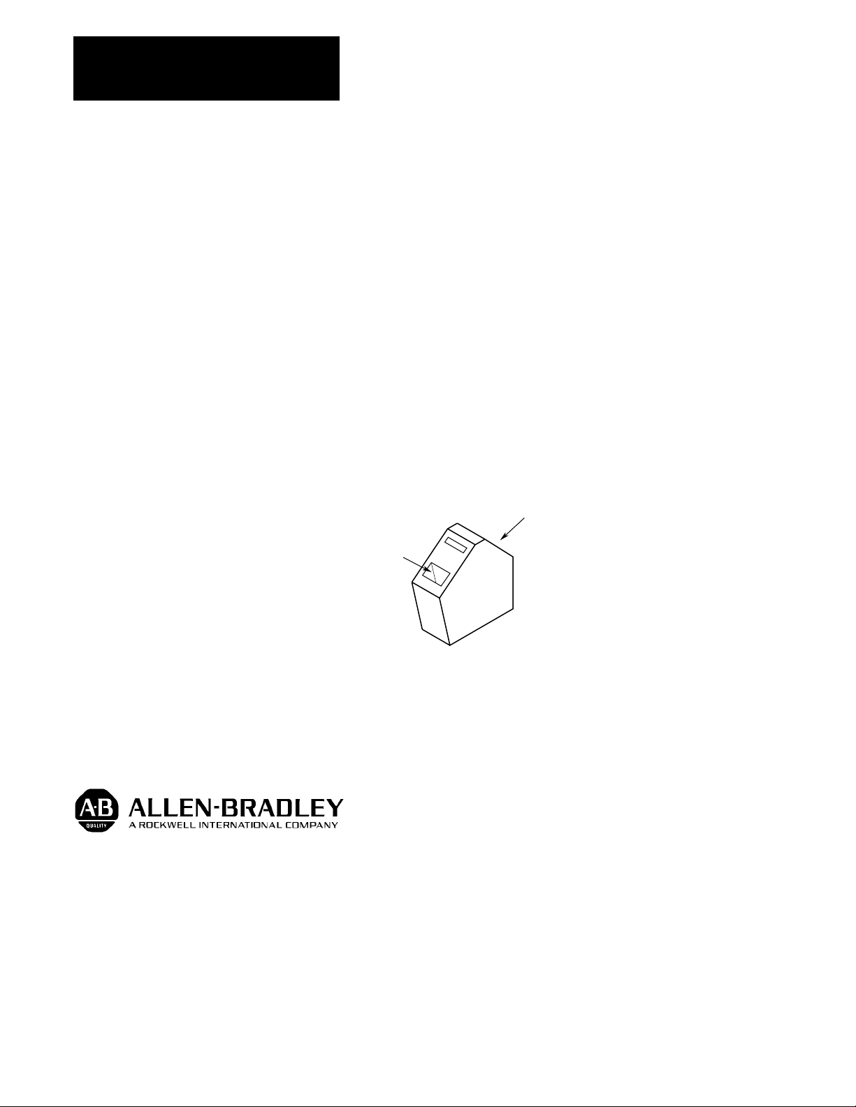
4. The terminal blocks used on the termination panels are a compression
type suitable for bare, stripped wire. Terminals will accept #16 AWG
(1.5 mm
2
) wire or smaller. To insert a wire, release the compression
lock by firmly pressing a narrow blade screwdriver into the slot on the
back of the terminal (see figure below). Insert the wire and release the
compression lock by removing the screwdriver.
Figure 1
Termination Panel Terminal Block
Insert Bare,
Stripped Wire
With offices in major cities worldwide.
Insert Narrow Blade Screwdriver
in Rear Slot to Release Lock
1
Allen-Bradley has been helping its customers improve productivity and quality for 90 years.
Allen-Bradley designs, manufactures and supports a broad range of control and automation
products worldwide. They include logic processors, power and motion control devices,
man-machine interfaces and sensors. Allen-Bradley is a subsidiary of Rockwell
International, one of the world’s leading technology companies.
WORLD
HEADQUARTERS
Allen-Bradley
1201 South Second Street
Milwaukee, WI 53204
USA
Tel: (1) 414 382-2000
Telex: 43 11 016
Fax: (1) 414 382-4444
Publication 8510-5.6 – April, 1993 P/N 152833
EUROPE/MIDDLE
EAST/
AFRICA
HEADQUARTERS
Allen-Bradley Europe
B.V.
Amsterdamseweg 15
1422 AC Uithoorn
The Netherlands
Tel: (31) 2975/43500
Telex: (844) 18042
Fax: (31) 2975/60222
ASIA/PACIFIC
HEADQUARTERS
Allen-Bradley (Hong Kong)
Limited
Room 1006, Block B, Sea View
Estate
2-8 Watson Road
Hong Kong
Tel: (852) 887-4788
Telex: (780) 64347
Fax: (852) 510-9436
CANADA
HEADQUARTERS
Allen-Bradley Canada
Limited
135 Dundas Street
Cambridge, Ontario N1R
5X1
Canada
Tel: (1) 519 623-1810
Fax: (1) 519 623-8930
Copyright 1993 Allen-Bradley Company, Inc. Printed in USA
LATIN AMERICA
HEADQUARTERS
Allen-Bradley
1201 South Second
Street
Milwaukee, WI 53204
USA
Tel: (1) 414 382-2000
Telex: 43 11 016
Fax: (1) 414 382-2400
 Loading...