

Page 1

ALLEN-BRADLEY
8510 AC Spindle Drive
Connector Kits
(Cat. No. 8510SA-CABC, 8510SA-CADC)
Instructions
Introduction Connections to the motor feedback resolver that are performed inside the
motor terminal box are made through an AMP Commercial MATE-N-LOK
connector. Two sizes of connectors are used depending on the motor type.
This publication will provide the information needed to properly install
these connectors.
The connector kit to use with a specific motor type is defined below.
Motor Type Connector Kit # Pins
Single winding 1327AB Series 8510SA-CABC 16
Dual winding 1327AD Series 8510SA-CADC 10
Refer to the 8510 User Manual, publication 8510-5.1 for detailed
information about the cable required and the connector pin assignments for
each of the motor types.
Assembling the Connector/Cable The following procedure outlines the steps needed to install the connector.
1. Verify that the connector kit includes the connector body and the
correct number of pins.
2. Remove the cable insulation and strip back the shields approximately
50 mm (2”). Strip about 4 mm (3/16”) of insulation from each wire.
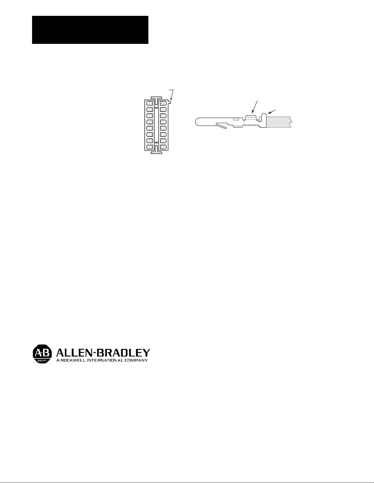
3. If available, use AMP crimp tool type 90123-2 to crimp the pins to the
wires. If the correct crimp tool is not available, any similar sized hand
crimp tool or pliers can be used to make the basic mechanical
connection. Solder (using rosin core solder) the wire into the connector
pin to complete the electrical connection. This assembly is shown in
Figure 1.
4. Insert the wires with (attached pins) into the connector location
specified in the 8510 User Manual. The connector pin designations are
shown in the Figure 1.
Important: Use care when orienting and inserting pins into connector.
Once pins have “snapped” into place, removal can be difficult.
Page 2
Instructions
8510 Connector Kits
Figure 1
Connector Assembly
Pin 1
Indicator
Bend Tabs Over Stripped Wire and Solder
2
4
6
8
10
12
14
16
3
5
7
9
11
13
15
Bend Over Wire Insulation
5. When mating this connector to the motor, assure that the wires on both
connector halves are not pulling the pins to the side and out of
alignment. Check pin alignment if the connector is difficult to insert.
Allen-Bradley has been helping its customers improve productivity and quality for 90 years.
Allen-Bradley designs, manufactures and supports a broad range of control and automation
products worldwide. They include logic processors, power and motion control devices,
man-machine interfaces and sensors. Allen-Bradley is a subsidiary of Rockwell
With offices in major cities worldwide.
WORLD
HEADQUARTERS
Allen-Bradley
1201 South Second Street
Milwaukee, WI 53204
USA
Tel: (1) 414 382-2000
Telex: 43 11 016
Fax: (1) 414 382-4444
Publication 8510-5.28 – April, 1993 P/N 152822
EUROPE/MIDDLE
EAST/
AFRICA
HEADQUARTERS
Allen-Bradley Europe
B.V.
Amsterdamseweg 15
1422 AC Uithoorn
The Netherlands
Tel: (31) 2975/43500
Telex: (844) 18042
Fax: (31) 2975/60222
International, one of the world’s leading technology companies.
ASIA/PACIFIC
HEADQUARTERS
Allen-Bradley (Hong Kong)
Limited
Room 1006, Block B, Sea View
Estate
2-8 Watson Road
Hong Kong
Tel: (852) 887-4788
Telex: (780) 64347
CANADA
HEADQUARTERS
Allen-Bradley Canada
Limited
135 Dundas Street
Cambridge, Ontario N1R
5X1
Canada
Tel: (1) 519 623-1810
Fax: (1) 519 623-8930
Fax: (852) 510-9436
Copyright 1993 Allen-Bradley Company, Inc. Printed in USA
LATIN AMERICA
HEADQUARTERS
Allen-Bradley
1201 South Second
Street
Milwaukee, WI 53204
USA
Tel: (1) 414 382-2000
Telex: 43 11 016
Fax: (1) 414 382-2400
 Loading...