

Page 1

8510 AC Spindle
Drive System
Programming Manual
Page 2

Important User Information
Solid state equipment has operational characteristics differing from those of
electromechanical equipment. “Safety Guidelines for the Application,
Installation and Maintenance of Solid State Controls” (Publication SGI-1.1
available from your local Allen-Bradley Sales Office or online at http://
www.ab.com/manuals/gi) describes some important differences between
solid stateequipmentand hard-wired electromechanical devices.Because of
this difference, and also because of the wide variety of uses for solid state
equipment, all persons responsible for applying this equipment must satisfy
themselves that each intended application of this equipment is acceptable.
In no event will the Allen-Bradley Company be responsible or liable for
indirect or consequential damages resulting from the use or application of
this equipment.
The examples and diagrams in this manual are included solely for
illustrative purposes. Because of the many variables and requirements
associated with any particular installation, the Allen-Bradley Company
cannot assume responsibility or liability for actual use based on the
examples and diagrams.
No patent liability is assumed by Allen-Bradley Company with respect to
use of information, circuits, equipment, or software described in this
manual.
Reproduction of the contents of this manual, in whole or in part, without
written permission of the Allen-Bradley Company is prohibited.
Throughout this manual we use notes to make you aware of safety
considerations.
ATTENTION: Identifies information about practices or
circumstances that can lead to personal injury or death, property
!
damage, or economic loss.
Attentions help you:
• identify a hazard
• avoid the hazard
• recognize the consequences
Important:Identifiesinformation that is especially important for successful
application and understanding of the product.
Shock Hazard labels may be located on or inside the drive to
alert people that dangerous voltage may be present.
SCANport is a trademark of Rockwell Automation.
PLC is a registered trademark of Rockwell Automation.
COLOR-KEYED is a registered trademark of Thomas & Betts Corporation.
IBM is a registered trademark of International Business Machines Corporation.
Windows 95 is a registered trademark of Microsoft Corporation.
Page 3

Introduction Chapter 1
Chapter Objectives 1-1. . . . . . . . . . . . . . . . . . . . . . . . . . . . . . . . . . . . . . . . .
Introduction 1-1. . . . . . . . . . . . . . . . . . . . . . . . . . . . . . . . . . . . . . . . . . . . . .
Menu Format and Conventions 1-1. . . . . . . . . . . . . . . . . . . . . . . . . . . . . . .
Programming Capabilities 1-1. . . . . . . . . . . . . . . . . . . . . . . . . . . . . . . . . . .
Display Description 1-3. . . . . . . . . . . . . . . . . . . . . . . . . . . . . . . . . . . . . . . .
Keypad Description and Operation 1-4. . . . . . . . . . . . . . . . . . . . . . . . . . . .
Accessing the DRIVE SETUP Menu 1-7. . . . . . . . . . . . . . . . . . . . . . . . . .
Programming Key Combinations 1-8. . . . . . . . . . . . . . . . . . . . . . . . . . . . .
Remote Programming 1-8. . . . . . . . . . . . . . . . . . . . . . . . . . . . . . . . . . . . . .
Programming Chapter 2
Chapter Objectives 2-1. . . . . . . . . . . . . . . . . . . . . . . . . . . . . . . . . . . . . . . . .
DRIVE SETUP Menu 2-1. . . . . . . . . . . . . . . . . . . . . . . . . . . . . . . . . . . . . .
GEAR RANGES Menu 2-4. . . . . . . . . . . . . . . . . . . . . . . . . . . . . . . . . . . . .
MOTOR SELECT Menu 2-6. . . . . . . . . . . . . . . . . . . . . . . . . . . . . . . . . . . .
PARAMETER SET Menu 2-6. . . . . . . . . . . . . . . . . . . . . . . . . . . . . . . . . . .
DRIVE TUNING Menu 2-10. . . . . . . . . . . . . . . . . . . . . . . . . . . . . . . . . . .
ORIENT SETUP Menu 2-21. . . . . . . . . . . . . . . . . . . . . . . . . . . . . . . . . . . .
ANALOG OUTPUT Menu 2-24. . . . . . . . . . . . . . . . . . . . . . . . . . . . . . . . .
Table of Contents
8510 Programming Manual
Drive Tuning Chapter 3
Chapter Objectives 3-1. . . . . . . . . . . . . . . . . . . . . . . . . . . . . . . . . . . . . . . . .
Tuning Introduction 3-1. . . . . . . . . . . . . . . . . . . . . . . . . . . . . . . . . . . . . . . .
Tuning Requirements 3-1. . . . . . . . . . . . . . . . . . . . . . . . . . . . . . . . . . . . . . .
Spindle/Servo Mode Tuning 3-2. . . . . . . . . . . . . . . . . . . . . . . . . . . . . . . . .
“Per Unit” System Description 3-4. . . . . . . . . . . . . . . . . . . . . . . . . . . . . . .
Spindle Orient Mode Tuning 3-5. . . . . . . . . . . . . . . . . . . . . . . . . . . . . . . . .
Parameter Record Appendix A
i
Page 4

Chapter
1
Introduction
Chapter Objectives This chapter explains the programming/setup system of the 8510. Included
is an explanation of the display, control features and general programming
to help you use and understand the 8510 programming system.
Introduction In addition to the standard metering and diagnostic functions explained in
the 8510 User Manual, the keypad and display are also used for programming all of the drive setup parameters through the DRIVE SETUP menu.
Menu Format and Conventions The menu system is based on the 16 character by 2 line display used in the
8510. The menu is arranged in a tree format to allow easy access to any
item. Menu items will be shown on the display two different ways:
1) UPPER CASE letters (capitals) indicate the item is a menu heading
with a group of sub-menus or parameter names below it.
2) Initial Capital letters indicate the item is the name of a parameter.
To help differentiate input/output names, programmable parameters and
programmable values printed in this manual, the following conventions
will be used.
Input and Output Names will appear in Initial Capital Letters
Programming Display Text will appear in italics
Menu Names will appear with ALL CAPITALS
Parameter Names will appear with Initial Capital Letters
Programmable Parameter Values will appear in “quotes”
Programming Capabilities The DRIVE SETUP menu is used to define the electrical configuration and
tune the dynamic performance of the 8510. The drive can be programmed
to provide optimum machine response for a variety of mechanical system
configurations and application requirements. The following paragraphs
explain some of the capabilities.
1. When used with a multi-speed spindle gearbox, a unique set of all
programmable parameter values can be set for each gear range. Up to
four gear ranges can be used. During drive operation, two discrete
inputs are used to select the appropriate gear range parameter set.
Tip: In applications that do not use gear boxes, the gear range data sets
can be used to optimize drive performance under widely varying load
conditions, to change the drive configuration for different operations, or
to increase the number of parameter setpoints that are available.
1-1
Page 5

Chapter 1
Introduction
2. When two speed, wide constant power range motors (1327AD series)
are used, unique parameter sets are used for the low speed and high
speed windings. The two speed motors can be combined with up to a
three speed gearbox for a total of six unique sets of programmable
parameters. During drive operation, a single discrete input will select
the appropriate motor speed range and speed range parameter set.
3. Within each gear range/motor winding data set, discrete inputs can
select one of three primary operating modes; spindle, servo or torque.
For each of these modes there are independent sets of parameter data
values to control the velocity command source and scaling along with
the system dynamics. Also, within servo mode, two different velocity
scaling ranges can be selected.
Gear Range Data Sets
A Gear Range Data Set is a grouping of parameters that define a gear
range/motor winding configuration. A typical gear range data set consists
of the following:
Data Set for Standard Motor or Low Speed Winding on a Dual Winding Motor
- Overall System Configuration
- Standard Motor or Low Speed Motor Winding Parameter Set
- Spindle Mode Configuration and Tuning
- Servo Mode Configuration and Speed Range Select
High Range Tuning
Low Range Tuning
- Torque Mode Configuration and Tuning
- Spindle Orient Configuration and Tuning
Data Set for High Speed Winding on a Dual Winding Motor
- Overall System Configuration
- High Speed Motor Winding Parameter Set
- Spindle Mode Configuration and Tuning
- Servo Mode Configuration and Speed Range Select
High Range Tuning
Low Range Tuning
- Torque Mode Configuration and Tuning
- Spindle Orient Configuration and Tuning
Tip: To simplify initial drive setup, a Copy Data command is available
(GEAR RANGES menu). After programming a complete gear range/motor
winding data set, this command can copy the data set to any other gear
range/motor winding data set. The programmer then makes changes as
required to the copied data set.
1-2
Refer to GEAR RANGES Menu in Chapter 2 for further information.
Page 6
Chapter 1
Introduction
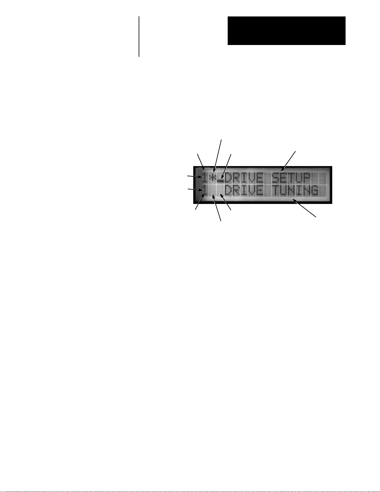
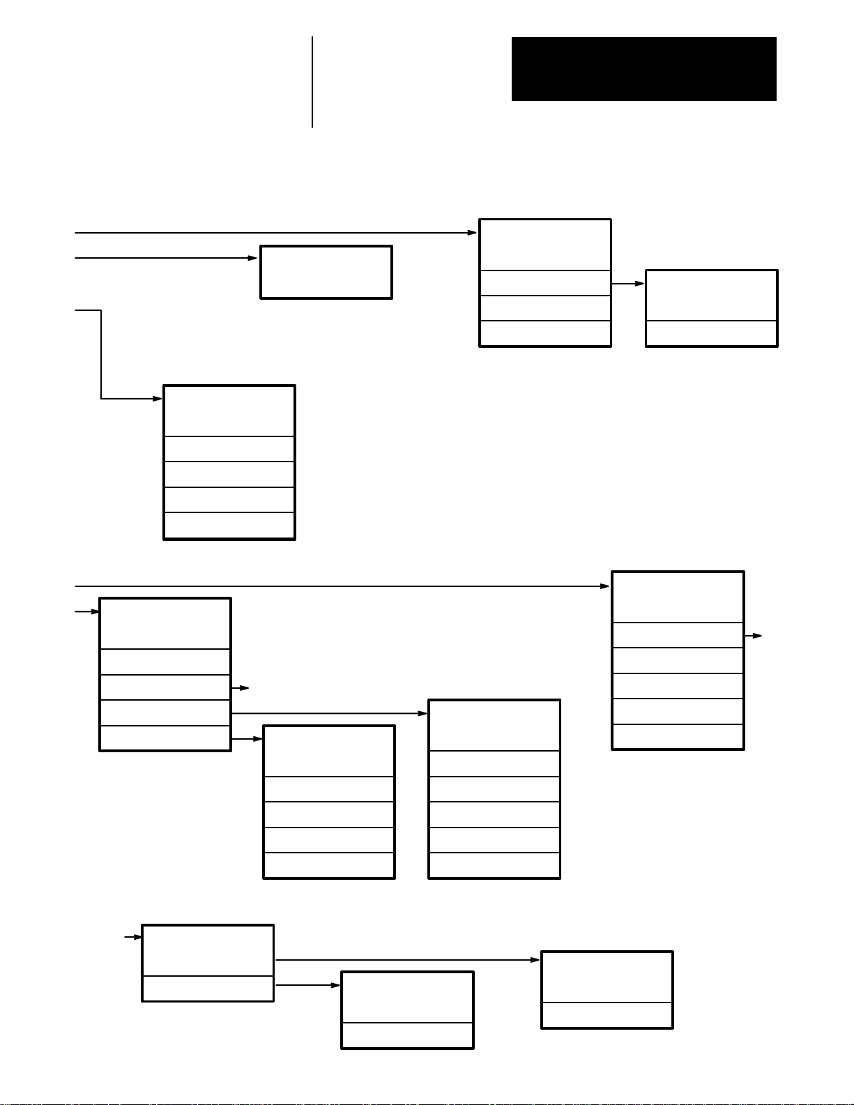
Display Description The 8510 display which is used for programming, as well as status and
diagnostic messages consists of a 16 character, 2 line, LCD (Liquid
Crystal) display. The display is divided into several different sections as
shown in Figure 1.1.
Figure 1.1
LCD Display
Motor Winding
Selected by Digital
Gear Range
Selected by Digital
Inputs
Line 1, Character 1
Line 2, Character 1
Inputs
Menu Level
Indicator
Menu Information
Gear Range
Selected for
Programming
(when applicable)
Menu Level
Indicator (when
applicable)
Motor Winding
Selected for Program-
ming
(when applicable)
Menu Information
Line 1, characters 1 & 2 – are used to display the gear range and motor
winding data set that is currently selected by the digital inputs and is being
used for drive operation. Character 1 will show the selected gear range
(1-4) and if a 2 speed motor is used, character 2 will show the motor
winding (H = high speed winding, L = low speed winding).
Line 1, character 3 – is a variable length bar (moving from the bottom up)
that represents the current depth (level) in the menu system.
Line 1, characters 4-16 – are used to display the name of the current menu
level or selected parameter. The menu options or parameter value
associated with the item displayed on line 1 will be displayed on line 2.
Line 2, characters 1 & 2 – are used to display the gear range and motor
winding data set that is currently selected for programming. Character 1
will show the selected gear range (1-4) and with 2 speed motors, character
2 will show the motor winding (L or H).
Line 2, character 3 – a variable length bar (moving from the bottom up)
that represents the current depth (level) in the menu system that has been
selected. For each level the user moves down, another bar is added to the
display.
Line 2, characters 4-16 – used to display the options that are available at
the current menu level or the value of the parameter that has been selected.
1-3
Page 7
Chapter 1
Introduction
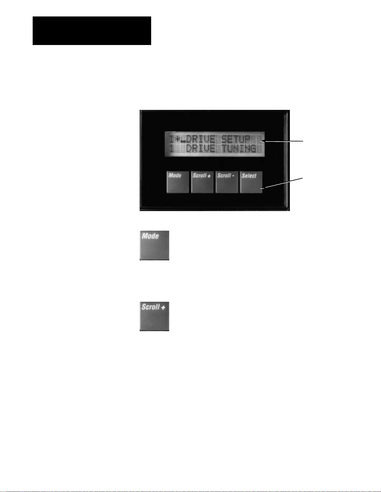
Keypad Description and Operation When programming in the DRIVE SETUP menu, the 8510 keypad will
have expanded functions not found in the DISPLAY TYPE menu.
Figure 1.2
8510 Keypad and Display
Display
Keypad
Pressing this key will cause the display to change to the
previous menu level within the DRIVE SETUP menu section.
If the top item of the menu (see Figure 2.2) is shown, the
Mode key will have no effect. If a parameter name and value
are displayed, pressing this key will cause the system to exit
that parameter without saving the displayed value. This key
effectively aborts a selection.
Pressing this key once will cause the parameter or sub-menu
names shown on line 2 of the display to increment to the
next possible choice for the menu listed on line 1. If this key
is pressed and held, the display will continuously index
through the possible selections until the key is released.
When scrolling through a list of sub-menu or parameter
names and the end of the menu list is reached, it will roll
over to the beginning and continue to increment. When
scrolling through parameter value selections, the
incrementing will stop at the end of the list and will not roll
over.
If line 2 is displaying the numerical value of a parameter, a
cursor will be displayed under the least significant digit.
When the Scroll + key is pressed, the value of this digit will
be increased. Pressing and holding this key will cause the
value to increment continuously until the maximum limit for
this parameter value is reached. The scrolling stops at the
maximum limit. The value will not roll over.
1-4
continued
Page 8

Chapter 1
Introduction
Scroll +
(continued)
To simplify programming large values, the cursor can be
moved one digit to the left by simultaneously pressing the
Scroll + and Scroll – keys. Pressing and holding both keys
will cause the cursor to continue indexing to the left. After
reaching the most significant digit position, it will roll over
to the least significant digit position.
Tip: The quickest method to program large values is to scroll
the first digit to the correct value, index the cursor one digit
to the left and scroll to set the value of the second digit, and
repeat the process for the other digits. Scrolling the value of
a specific digit will only change the value of digits at or to
the left of the cursor.
The function of this key is identical to the Scroll+ key except
that it causes the display to decrement rather than increment.
If a menu name is shown on line 1, pressing this key will
cause the sub-menu or parameter shown on line 2 of the
display to become the active menu or parameter. This
sub-menu or parameter name will move to line 1 and the new
menu choices or parameter value will be shown on line 2.
If a parameter name is shown on line 1 and the parameter
value is on line 2, pressing Select will cause the displayed
parameter value to be stored in RAM. This value is also used
as the current operating parameter value. After the parameter
value has been stored in RAM, the display will return to the
previous menu display with the parameter name on line 2 of
the display.
If the Mode key is used to return the display to the previous
menu display, any parameter value changes will not be stored
in RAM.
Important: All parameter value changes are initially stored
in RAM. To save the data to EEPROM it is necessary to exit
the DRIVE SETUP menu and return to the DISPLAY TYPE
menu. Upon exiting DRIVE SETUP, all parameter changes
are automatically stored into EEPROM. If power is removed
from the drive or the drive is reset before the changes have
been stored in EEPROM, these changes will be lost. When
data is being written to the EEPROM, the “←” symbol will
momentarily show as character 3 on line 2 of the display.
continued
1-5
Page 9

Chapter 1
Introduction
Select
(continued)
Any time a parameter name is selected, the parameter value
that is initially shown on line 2 is the value that is currently
stored in RAM as the operating parameter value.
To speed system setup, it is possible to change the value of
any parameter while the drive is operating. When a parameter value is changed and the Select key is pushed, there is a
time delay of about 0.75-1.0 second before the value is used
in drive operation. Changes to the specified motor or drive
type or to the analog output definition will only become effective when the value changes are actually stored in EEPROM the next time the Enable input is energized.
Important: When trying to change parameters while the
drive is operating and then observe the resultant operation,
verify that the actual operating gear range and motor winding
selected by the drive inputs (and shown in characters 1 & 2
of line 1 of the display) matches the programming gear range
and motor winding shown by characters 1 & 2 of line 2. If
they do not match, any parameter changes will be made to a
different gear range data set, resulting in no effect on current
drive operation and possible erratic operation when the other
data set is used.
ATTENTION: Changing certain parameter values can result in
!
significantly different drive operation characteristics, such as
reversing direction of rotation or changing the motor speed for a
specific input command level. If parameters are changed while
the drive is operating, the user is responsible for assuring that
the changes in operating characteristics that result from these
changes will not result in unsafe machine operating conditions
1-6
Page 10

Chapter 1
Introduction
Accessing the DRIVE SETUP Menu To help guard against access to the drive setup programming parameters by
untrained personnel, a special key combination is required to access the
DRIVE SETUP menu. To access this menu, simultaneously press and hold
the Mode, Scroll + and Scroll – keys for about 3 seconds. The DRIVE
SETUP menu and a second bar at character 3 of line 1 will be displayed.
This menu allows access to all of the drive setup parameters that are
needed to integrate the motor and drive to the machine. The programmer
will be able to:
- Select and define gear ranges
- Select the motor
- Select the drive and set basic configuration parameters
- Dynamically tune the drive
- Setup spindle orient
- Configure the analog outputs
Exiting the DRIVE SETUP Menu
Upon completion of setup, pressing and holding the Mode and Scroll –
keys will return the display to the DISPLAY TYPE menu.
Important: Exiting DRIVE SETUP and returning to the DISPLAY TYPE
menu is the only
way to cause all parameter value changes to be written to
EEPROM for permanent storage.
Default Data
When the drive is shipped from the factory, default values are programmed
for most of the drive configuration data. The values that are chosen will
result in relatively low performance operation up to about half speed with
most types of systems.
Important: There are three parameters that have no default value assigned.
Two of these parameters must be programmed by the user before trying to
enable the drive or the drive will fault. These parameters are l) MOTOR
SELECT– Catalog Num and 2) PARAMETER SET – ELECT CONFIG –
Drive Cat Num. The third parameter, ORIENT SETUP – FEEDBACK
DEFN – Encoder Lines, must be programmed before attempting to use the
drive to perform spindle orient.
1-7
Page 11

Chapter 1
Introduction
Programming Key Combinations Several functions are implemented through the use of specific
combinations of multiple keys.
n Access to the DRIVE SETUP menu is accomplished by simultaneously
pressing and holding the Mode, Scroll +, and Scroll – keys for about 3
seconds.
n Pressing Mode and Scroll – simultaneously will cause the system to
change to the first display screen in the DRIVE SETUP menu. Pressing
these keys again will exit the DRIVE SETUP menu and return the
display to the DISPLAY TYPE menu.
Important: Exiting DRIVE SETUP and returning to the DISPLAY TYPE
menu is the only
way to cause all parameter value changes to be written
to EEPROM for permanent storage.
n When programming numerical values for a programmable parameter, the
cursor can be indexed one digit to the left by simultaneously pressing
Scroll + and Scroll –.
Remote Programming Program Upload/Download
Initially, during normal drive integration, the drive is programmed using
the integral keypad and display and all programmed data is stored in the
EEPROM on the I/O Board. The I/O board contains an RS-232 port that
allows offline software to access this EEPROM data.
A file transfer utility, Catalog Number 8510SA-SFTU, that runs on a DOS
based, IBM
compatible personal computer, will allow the contents of the
EEPROM to be uploaded through the RS-232 port and stored in a file in
the computer. This same utility can download this data file to the EEPROM
of another drive to duplicate the original drive setup. This allows rapid
setup of machines that are in series production by simply downloading the
drive setup from a master file. Also, a user can maintain files for each drive
in the facility and quickly duplicate the original drive setup in case the
setup is accidentally changed.
Offline Programming
A spindle drive configuration software package, Catalog Number
8510SA-SSDC, allows complete offline configuration programming of the
8510 drive. This software runs as part of the Allen-Bradley Offline
Development System (ODS) software that is used to configure the 9/Series
CNC and IMC motion controller hardware. It also requires a DOS based,
IBM compatible personal computer. Rather than using the integral keypad
and display on the drive, a full screen display and complete keyboard can
be used to enter all drive configuration data. The data file is then
downloaded via the RS-232 port into the 8510 drive. To make the final
adjustment of the analog input calibration and the drive gains, it may be
necessary to use the integral drive programming keypad.
1-8
Page 12
Chapter
2
Programming
Chapter Objectives Chapter 2 provides a detailed look at the programming associated with the
DRIVE SETUP menu found in the 8510. Included are complete
descriptions of the various parameters that can be programmed during
drive setup.
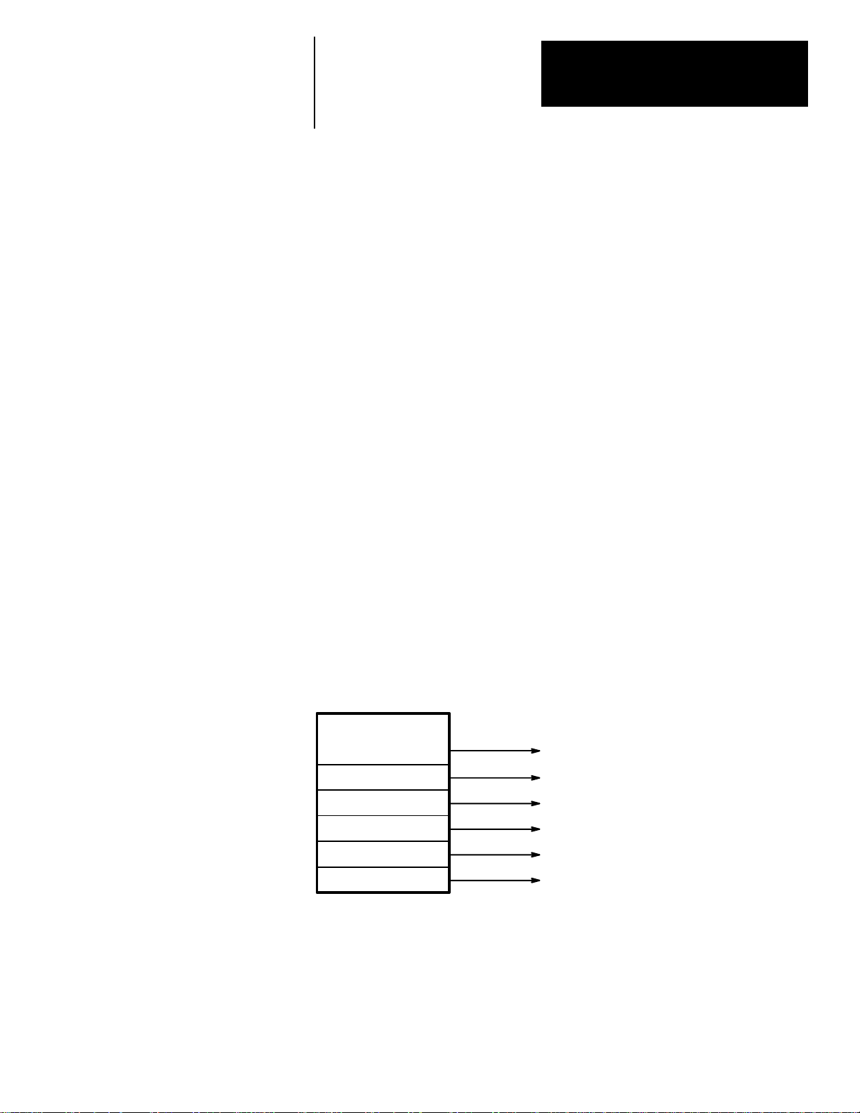
DRIVE SETUP Menu The DRIVE SETUP menu (see Figure 2.1) is the top level of the setup
parameters. The menu is accessed by simultaneously pressing and holding
the Mode, Scroll +, and Scroll – keys for about 3 seconds.
An overall view of the complete DRIVE SETUP menu is shown in
Figure 2.2.
The remaining sections in this chapter provide detailed parameter
descriptions used when programming. After most descriptions, a data
format will be provided. This indicates the entry format expected by the
programming system or the scroll choices that are available. Refer the page
numbers provided in Figure 2.1 to help locate specific programming
information.
Figure 2.1
Drive Setup Menu Tree
DRIVE SETUP
GEAR RANGES
MOTOR SELECT
PARAMETER SET
DRIVE TUNING
ORIENT SETUP
ANALOG OUTPUT
See Page 2-12
See Page 2-14
See Page 2-14
See Page 2-18
See Page 2-29
See Page 2-32
2-9
Page 13
Chapter 2
Programming
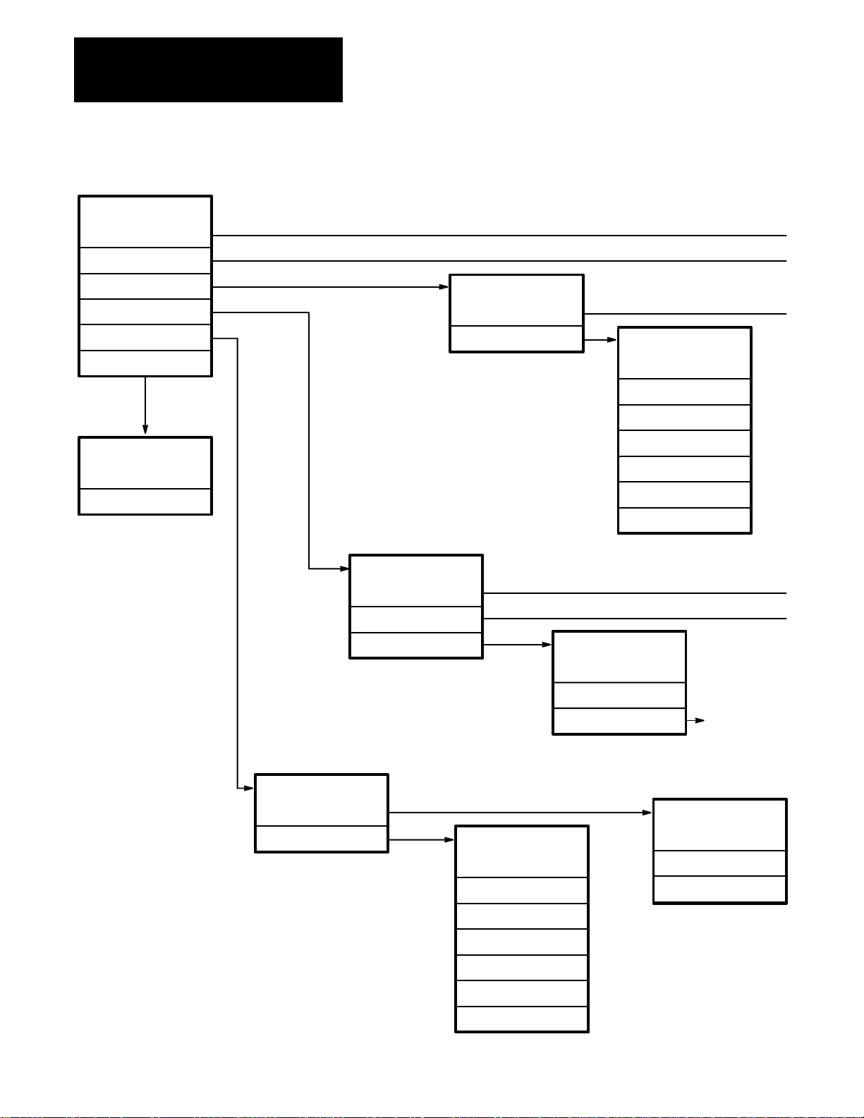
DRIVE SETUP
GEAR RANGES
MOTOR SELECT
Figure 2.2
DRIVE SETUP Menu Tree
PARAMETER SET
DRIVE TUNING
ORIENT SETUP
ANALOG OUTPUT
ANALOG OUTPUT
Output #1
Output #2
DRIVE TUNING
SPINDLE MODE
SERVO MODE
TORQUE MODE
PARAMETER SET
ELECT CONFIG
SPINDL PRESET
SPINDL PRESET
Overspd Trip
Acc Rate #1
Acc Rate #2
Low Torq Lmt
At–Set–Speed
Speed Detect
Load Detect
TORQUE MODE
Torque Enable
2-10
ORIENT SETUP
FEEDBACK DEFN
ORIENT TUNE
ORIENT TUNE
Position Data
Preset Angle
Orient Speed
Orient Start
In-Position
Dir From Stop
Hold Position
Max Speed
ANALOG CAL
A
FEEDBACK DEFN
Encoder Type
Encoder Lines
Encdr Phasing
Page 14
Chapter 2
Programming
GEAR RANGES
ELECT CONFIG
Drive Cat Num
Motor Phasing
Cmnd Phase #1
Cmnd Phase #2
Enable Torque
SERVO MODE
Analog In #
A/D Conv Type
MOTOR SELECT
Catalog Num
Select Range
SET RATIOS
Copy Data
Default Data
SET RATIOS
Spindle Revs
Motor Revs
SPINDLE MODE
Cmnd Source
ANALOG CAL
Max Cmnd Spd
A
ANALOG CAL
HI SPD RANGE
LO SPD RANGE
A
ANALOG CAL
MEASURE INPUT
PROGRAM VALUE
A
LO SPD RANGE
Max Cmnd Spd
Servo P Gain
Servo I Gain
Droop In Run
Speed Cal
HI SPD RANGE
Max Cmnd Spd
Servo P Gain
Servo I Gain
Droop In Run
Droop In Hold
Speed Cal
PROGRAM VALUE
Zero Volt In
Max +Volt In
Spindl P Gain
Spindl I Gain
Speed Cal
MEASURE INPUT
Zero Volt In
Max +Volt In
2-11
Page 15
Chapter 2
Programming
GEAR RANGES Menu This menu allows the gear ranges to be defined and selected for
programming. Refer to Figure 2.3 for an example of the GEAR RANGES
menu and the paragraphs that follow for parameter explanations.
Figure 2.3
GEAR RANGES Menu Tree
GEAR RANGES
Select Range
SET RATIOS
Copy Data
Default Data
SET RATIOS
Spindle Revs
Motor Revs
The two Gear Range Active inputs define which gear range data set is
currently being used for motor control. However, these inputs do not select
the gear range data set that can currently be programmed. The GEAR
RANGES menu is used to select the gear range data set to program.
• The first character of the first line of the display shows the gear range
data set that is selected as the operating
data set.
• The first character of the second line of the display shows the gear range
data set that has been selected for programming
.
Select Range
This parameter allows selection of the gear range data set that is to be
programmed. The programming gear range has two parts - the physical
gear range and the motor winding. If dual winding motors are used, the
parameters must be programmed for both the low and high speed windings
in each gear range.
2-12
The physical gear range is shown in character 1, line 2 of the display, with
the motor winding (dual winding motors only) shown in character 2. Dual
winding motors use an L or an H to designate the Low and High speed
windings. The second position will be blank if a motor is not selected or a
single speed motor is being used. A scroll sequence is used to select the
low speed and high speed motor windings for a particular gear range before
advancing to the next gear (i.e. 1L, 1H, 2L, 2H, etc.). With dual winding
motors, only three physical gear ranges can be used since only 6 data sets
are stored.
Possible Choices: 1, 2, 3, 4, 1L, 1H, 2L, 2H, 3L, 3H
Default Value 1
Page 16

Chapter 2
Programming
SET RATIOS
This item defines the gear range ratio.
Spindle Revs
This parameter defines half of the gear ratio. The gear ratio must be
expressed as a ratio of two whole numbers and is stated as the number of
spindle revolutions for a certain number of motor revolutions. Enter the
number of spindle revolutions here.
Data Range: 00000 to 30000
Default Value: 00001
Motor Revs
The Motor Revs parameter programs the other half of the gear ratio. This
parameter defines the number of motor revolutions required for the
number of spindle revolutions specified above. For Example: a 4.3333:1
speed reduction would be specified as Spindle Revs = 3 and Motor Revs =
13.
Data Range: 00000 to 30000
Default Value: 00001
Copy Data
This parameter allows data from a previously programmed gear range to be
copied to the gear range that is currently selected for programming. When
selected, the bottom line can be scrolled through the gear ranges starting at
“RANGE: 1.”
Possible Choices: NO COPY, RANGE: 1, RANGE: 2, . . ., RANGE: 3H
Default Value: NO COPY
Default Data
Default Data will cause all data stored in the gear range currently selected
for programming to be reset to the factory default values. This parameter is
used to confirm that reset is desired.
Possible Choices: NO, YES
Default Value: NO
2-13
Page 17

Chapter 2
Programming
MOTOR SELECT Menu This menu (Figure 2.4) selects the motor that will be used with this drive.
Figure 2.4
MOTOR SELECT Menu Tree
MOTOR SELECT
Catalog Num
Catalog Num
This parameter lists the available spindle motors. Simply select the catalog
number of the motor being used. If a motor was previously selected, that
number will be displayed. If a motor was not previously selected, the
display will show “NONE SELECTED.”
Important: The default parameters do not include the motor type. This
parameter must be programmed before attempting to enable the drive or a
fault will occur.
Data Format: 1327AB-AFL-15
Default Value: NONE SELECTED
PARAMETER SET Menu The PARAMETER SET menu allows the selection and programming of
basic drive configuration parameters and preset parameters.
Figure 2.5
PARAMETER SET Menu Tree
PARAMETER SET
ELECT CONFIG
SPINDL PRESET
SPINDL PRESET
Overspd Trip
Acc Rate #1
Acc Rate #2
Low Torq Lmt
At–Set–Speed
Speed Detect
Load Detect
ELECT CONFIG
Drive Cat Num
Motor Phasing
Cmnd Phase #1
Cmnd Phase #2
Enable Torque
2-14
Page 18

Chapter 2
Programming
ELECT CONFIG
This menu allows the user to select electrical configuration parameters for
programming.
Drive Cat Num
This parameter lists the available drive catalog numbers for selection.
Simply select the catalog number of the drive being used. If a catalog
number had previously been entered, it will be displayed. If a catalog
number was not previously selected, the display will show “NONE
SELECTED.”
Important: The default parameters do not include the drive type. This
parameter must be programmed before attempting to enable the drive or a
fault will occur.
Possible Choices: NONE SELECTED, 8510A-A04, 8510A-A06, 8510A-A11,
8510A-A22
Data Format: 8510A-A04
Default Value: NONE SELECTED
Motor Phasing
This parameter allows the electrical phase sequence of the motor control
loops to be reversed without physically changing the wiring to the motor.
If incorrectly set, the motor may run slowly or oscillate between forward
and reverse rotation.
Possible Choices: FORWARD, REVERSE
Default Value: FORWARD
Cmnd Phase #1
Cmnd Phase #1 allows the polarity of Analog Input #1 to be reversed
inside the drive without reversing the actual wiring.
Possible Choices: FORWARD, REVERSE
Default Value: FORWARD
Cmnd Phase #2
Cmnd Phase #2 allows the polarity of Analog Input #2 to be reversed
inside the drive without reversing the actual wiring.
Possible Choices: FORWARD, REVERSE
Default Value: FORWARD
Enable Torque
Determines whether or not the drive will produce motor holding torque
when the Drive Enable command is On, but the Forward and Reverse
Run commands are both Off or On. The “With Run” selection means that
one of the Run commands must be present before the motor will produce
torque.
Possible Choices: WITH RUN, WITHOUT RUN
Default Value: WITH RUN
2-15
Page 19

Chapter 2
Programming
SPINDL PRESET
Selects the various Spindle Mode parameters and performance detectors.
Overspd Trip
Sets the overspeed trip point . The drive will shut down at this point and
cause the motor to coast to a stop. Set this parameter at least 10% higher
than expected maximum speed to avoid nuisance trips.
Data Range: RPM 00000 to 30000
Default Value: 08000
Acc Rate #1
Sets the acceleration rate ramp generator for the ramp rate that is used in
spindle mode when the Accel/Decel Rate Select input is turned Off. The
rate is defined in seconds/1000 rpm of speed change. This accel/decel
rate is achieved only if the required torque does not exceed the torque
limit level.
Data Range: S/KRPM 000.00 to 009.99
Default Value: 001.00
Acc Rate #2
Sets the acceleration rate ramp generator for the ramp rate that is used in
spindle mode when the Accel/Decel Rate Select input is On. The rate is
defined in seconds/1000 rpm of speed change. This accel/decel rate is
achieved only if the required torque does not exceed the torque limit
level.
Data Range: S/KRPM 000.00 to 009.99
Default Value: 001.00
Low Torq Lmt
This parameter sets the level of torque limit used when the Low Torque
Limit Select input is On. The torque is defined as a percent of the
continuous rated torque of the specific motor/drive combination and
cannot exceed the peak torque capacity of the motor (1.2 x 30 minute
motor rating).
Data Range: % 000 to 250
Default Value: % 025
At-Set-Speed
This parameter determines how close the actual speed must be to the
commanded speed before the At Speed Indicator output is On. The data is
stated as a percent of the commanded speed. If the percent of commanded
speed gives a value less than 25 rpm, then a fixed ±25 rpm band is used
for the test.
Data Range: % 000 to 100
Default Value: % 010
2-16
Page 20

Chapter 2
Programming
Speed Detect
The Speed Detect parameter determines the speed at which the Speed
Level Indicator output changes state. If the motor speed is above this
programmed level, the output is Off.
Data Range: RPM 00000 to 30000
Default Value: 00300
Load Detect
The Load Detect parameter determines the commanded torque level at
which the Load Level Indicator output changes state. If the torque
command exceeds this programmed level, the output is On. The data
defines the torque as a percent of the continuous rated torque of the
specific motor/drive combination and cannot exceed the peak torque
capacity of the motor (1.2 x 30 minute motor rating).
Data Range: % 000 to 250
Default Value: % 125
2-17
Page 21

Chapter 2
Programming
DRIVE TUNING Menu This menu allows selection of the drive setup and tuning procedure for
each of the different operating modes. Refer to Figure 2.6.
Figure 2.6
DRIVE TUNING Menu Tree
DRIVE TUNING
SPINDLE MODE
SERVO MODE
TORQUE MODE
TORQUE MODE
Torque Enable
Max Speed
ANALOG CAL
SERVO MODE
Analog In #
A/D Conv Type
ANALOG CAL
A
HI SPD RANGE
LO SPD RANGE
LO SPD RANGE
Max Cmnd Spd
Servo P Gain
Servo I Gain
Droop In Run
Speed Cal
SPINDLE MODE
Cmnd Source
ANALOG CAL
Max Cmnd Spd
A
Spindl P Gain
Spindl I Gain
Speed Cal
HI SPD RANGE
Max Cmnd Spd
Servo P Gain
Servo I Gain
Droop In Run
Droop In Hold
Speed Cal
A
2-18
ANALOG CAL
A
MEASURE INPUT
PROGRAM VALUE
PROGRAM VALUE
Zero Volt In
Max +Volt In
MEASURE INPUT
Zero Volt In
Max +Volt In
Page 22

Chapter 2
Programming
SPINDLE MODE
This menu selects the various setup and tuning procedures needed to set the
operating parameters that are used when the Spindle/Servo Mode Select
input is Off.
Cmnd Source
This parameter is used to specify the source of the speed command. The
command can be from Analog Input #1 or from the optional 16 Bit
Digital Speed Command/Orient Position inputs on connector CN10. If
the digital inputs are used, the data can be in binary or BCD format. In
binary mode, maximum speed equals 2
16
– 1 or 65,535 counts. 1 LSB =
Max Cmnd Spd / 65535. In BCD mode, maximum speed equals 9,999
counts. In this mode, 1 LSB = Max Cmnd Spd / 9999. The digital inputs
can be used for either orient position command or spindle speed
command, but not both.
Possible Choices: ANALOG, 4 DIGIT BCD, 16 BIT BINARY
Default Value ANALOG
ANALOG CAL
This menu allows selection of two alternative methods to calibrate the
analog input channel. This sequence is not required if digital speed
commands are being used.
MEASURE INPUT
Allows selection of the steps required to calibrate the analog input by
actually measuring the value of the applied signal voltages. This is the
preferred method for calibrating the analog input.
Zero Volt In
This parameter requires the user to input the command voltage that is
equal to the zero speed command. When the Select key is pressed, the
control will read the input voltage on Analog Input #1 and use that as
the zero speed reference value. The display will function as a
voltmeter to show the voltage being read on the analog input.
Data Range: VOLT 00.000 to ±09.999
Default Value 0.000
Max +Volt In
This parameter requires the user to input the positive command
voltage that is equal to the maximum speed command. When the
Select key is pressed, the control will read the input voltage on Analog
Input #1 and use that as the maximum speed command reference
value. The display will function as a voltmeter to show the voltage
being read on the analog input.
Data Range: VOLT 00.000 to 10.000
Default Value 10.000
2-19
Page 23

Chapter 2
Programming
PROGRAM VALUE
This menu allows selection of the steps required to calibrate the analog
input by presetting the display as a normal scrolled variable. Use this
calibration method if the actual command voltages are not available.
Zero Volt In
This parameter requires the user to program the value of the command
voltage that is equal to the zero speed command.
Data Range: VOLT 0.000 to ±9.999
Default Value 0.000
Max +Volt In
This parameter requires the user to program the value of the command
voltage that is equal to the maximum speed command.
Data Range: VOLT 00.000 to 10.000
Default Value 10.000
Max Cmnd Spd
Defines the maximum motor speed that is to correspond to the maximum
input command. The maximum motor speed can be programmed to any
level required by the application (but less than the maximum allowable
for the motor/drive combination) and achieve full scale speed command
resolution at that speed.
Data Range: RPM 00000 to 30000
Default Value 03000
The tuning parameters in the 8510 drive are based on the “per unit” system.
For this drive the base quantities are defined as follows:
1 p.u. Torque = Peak Motor Torque
1 p.u. Velocity or Velocity Error = Motor Base Speed
1 p.u. Inertia = Time to accelerate to 1 p.u. Velocity with 1 p.u. Torque
Refer to Chapter 3 for a detailed description of drive tuning and the use of
the “per unit” system in determining optimum drive tuning parameters.
Spindl P Gain
The velocity loop proportional gain used in the spindle mode is set with
this parameter. This data is programmed in Per Unit Torque / Per Unit
Velocity Error or % Torque / % Velocity Error.
Data Range: 000.0 to 200.0
Default Value 005.0
2-20
Page 24

Chapter 2
Programming
Spindl I Gain
The velocity loop integral gain used in the spindle mode is set with this
parameter. This data is programmed in Per Unit Torque / Per Unit
Velocity Error/second or % Torque / % Velocity Error / second. The units
for this parameter are 1/seconds.
Data Range: 1/S 00.00 to 50.00
Default Value 00.20
Speed Cal
This parameter allows exact matching of the speed command to the actual
motor speed. When an analog input equal to the maximum spindle speed
command is supplied from the CNC, the Scroll keys can be used to adjust
the motor speed until the displayed actual speed matches the commanded
speed. Press the Select key to store the setting.
This could be considered a fine tuning of the Max Cmnd Spd parameter.
As the appropriate Scroll key is pressed, a multiplier factor for the Max
Cmnd Spd parameter is incremented in 0.04% steps. There is a time delay
of approximately one second after the multiplier is changed until it can be
observed in the system operation. During this operation, the display is
operating as a digital speed meter showing current motor speed.
Reprogramming the Max Cmnd Spd parameter will reset this multiplier to
zero.
Data Range: RPM 00000 to 30000
Default Value 0.00%
SERVO MODE
This menu selects the various setup and tuning procedures needed to set the
operating parameters that are used when the Spindle/Servo Mode Select
input is On.
Analog In #
Analog In # determines which analog input is going to be used for the
velocity command in servo mode. If the drive is to operate in torque
mode, Analog Input #1 must be used for the velocity command.
Possible Choices: INPUT #2, INPUT #1
Default Value INPUT #2
2-21
Page 25

Chapter 2
Programming
A/D Conv Type
This parameter determines which A/D converter will be used with the
servo mode analog input signal. The standard A/D converter is a 10 bit
converter with auto-ranging capabilities that gives an effective 14 to 17
bits resolution for positioning applications.
However, for large command changes, the autoranging function
introduces a time delay. The full input range of +10 volts to –10 volts is
broken into 32 equal steps of 0.625 volts. Within one increment, A/D
conversions are made in 0.8 ms. To shift the input level one increment
requires 0.8 ms. For a maximum input change from +10 volts to –10
volts, the maximum delay is 26.4 ms. The optional A/D converter is a full
14 bit, high speed converter providing an input sample every 0.8 ms. This
converter must be used for precision continuous path contouring
applications and very high response positioning applications.
Possible Choices: STANDARD, 14 BIT LINEAR
Default Value STANDARD
ANALOG CAL
This menu allows selection of two alternative methods to calibrate the
analog input channel.
MEASURE INPUT
Allows selection of the steps required to calibrate the analog input by
actually measuring the value of the applied signal voltages. This is the
preferred method for calibrating the analog input.
Zero Volt In
This parameter requires the user to input the command voltage that is
equal to the zero speed command. When the Select key is pressed, the
control will read the input voltage on the input selected by the Analog
Input # parameter and use that as the zero speed reference value. The
display will function as a voltmeter to show the voltage being read on
the analog input.
Data Range: VOLT 00.000 to ±09.999
Default Value 0.000
Max +Volt In
This parameter requires the user to input the positive command
voltage that is equal to the maximum speed command. When the
Select key is pressed, the control will read the input voltage on the
input selected by the Analog Input # parameter and use that as the
maximum speed command reference value. The display will function
as a voltmeter to show the voltage being read on the analog input.
Data Range: VOLT 00.000 to 10.000
Default Value 10.000
2-22
Page 26

Chapter 2
Programming
PROGRAM VALUE
This is a menu title that allows selection of the steps required to
calibrate the analog input by presetting the display as a normal scrolled
variable. Use this calibration method if the actual command voltages are
not available.
Zero Volt In
This parameter requires the user to program the value of the command
voltage that is equal to the zero speed command.
Data Range: VOLT 0.000 to ±9.999
Default Value 0.000
Max +Volt In
This parameter requires the user to program the value of the command
voltage that is equal to the maximum speed command.
Data Range: VOLT 00.000 to 10.000
Default Value 10.000
HI SPD RANGE
This menu selects the various setup and tuning parameters that are used
when the Spindle/Servo Mode Select input is On and the Servo Input
Scaling Low/High input is On. Also, the velocity loop tuning parameters
set for this mode will be used when the drive is performing the spindle
orient operation.
Max Cmnd Spd
Defines the maximum motor speed that will correspond to the
maximum input command. The maximum motor speed can be
programmed to any level required by the application (but less than the
maximum allowable speed for the motor/drive combination) and
achieve full scale speed command resolution at that speed. Typically
this parameter would be used for C axis rapid traverse, solid tapping
operation, or possibly precision spindle orient operations from the CNC
and would be set to a relatively low speed.
Data Range: RPM 00000 to 30000
Default Value 00084
The tuning parameters in the 8510 drive are based on the “per unit” system.
For this drive the base quantities are defined as follows:
1 p.u. Torque = Peak Motor Torque
1 p.u. Velocity or Velocity Error = Motor Base Speed
1 p.u. Inertia = Time to accelerate to 1 p.u. Velocity with 1 p.u. Torque
Refer to Chapter 3 for a detailed description of drive tuning and the use of
the “per unit” system in determining optimum drive tuning parameters.
2-23
Page 27

Chapter 2
Programming
Servo P Gain
The velocity loop proportional gain used in the servo mode is set with
this parameter. This data is programmed in Per Unit Torque / Per Unit
Velocity Error or % Torque / % Velocity Error.
Data Range: 000.0 to 200.0
Default Value 5.00
Servo I Gain
The velocity loop integral gain used in the servo mode is set with this
parameter. This data is programmed in Per Unit Torque / Per Unit
Velocity Error/second or % Torque / % Velocity Error / second. The
units for this parameter are 1/seconds.
Data Range: l/S 00.00 to 50.00
Default Value 00.20
Droop In Run
Droop In Run sets a maximum limit on the effective low frequency
velocity loop gain that the integrator can generate during normal
running mode operation. This parameter limits stick-slip motion during
very low speed C axis operation. The data is expressed in Per Unit
Velocity Error / Per Unit Torque or % Velocity Error / % Torque.
Data Range: 0.000 to 7.999
Default Value 0.001
Droop In Hold
Sets a maximum limit on the effective low frequency velocity loop gain
that the integrator can generate when the spindle is within the
in-position error band limit during spindle orient operation. This can
allow accurate positioning without excess stick-slip motion. The data is
expressed in Per Unit Velocity Error / Per Unit Torque or % Velocity
Error / % Torque.
Data Range: 0.000 to 7.999
Default Value 0.001
2-24
Page 28

Chapter 2
Programming
Speed Cal
The Speed Cal parameter allows exact matching of the speed command
to the actual motor speed in order to precisely set position loop gain.
When the velocity command from a closed position loop move
commanded by the CNC is input to the drive, the Scroll keys can be
used to adjust the motor speed until the exact following error value
required in the CNC is achieved. Press the Select key to store the
setting.
This could be considered a fine tuning of the Max Cmnd Spd parameter.
As the appropriate Scroll key is pressed, a multiplier factor for the Max
Cmnd Spd parameter is incremented in 0.04% steps. There is a time
delay of approximately one second after the multiplier is changed until
it can be observed in the system operation. During this operation, the
display is operating as a digital speed meter showing current motor
speed. Reprogramming the Max Cmnd Spd parameter will reset this
multiplier to zero.
Data Range: RPM 00000 to 30000
Default Value 0.00 %
LO SPD RANGE
This menu selects the various setup and tuning parameters that are used
when the Spindle/Servo Mode Select input is On and the Servo Input
Scaling Low/High input is Off.
Max Cmnd Spd
Defines the maximum motor speed that will correspond to the
maximum input command. The maximum motor speed can be
programmed to any level required by the application (but less than the
maximum allowable speed for the motor/drive combination) and
achieve full scale speed command resolution at that speed. Typically
this parameter would be used to obtain maximum resolution for C axis
contouring mode and would be set to a very low speed.
Data Range: RPM 00000 to 30000
Default Value 00030
The tuning parameters in the 8510 drive are based on the “per unit” system.
For this drive the base quantities are defined as follows:
1 p.u. Torque = Peak Motor Torque
1 p.u. Velocity or Velocity Error = Motor Base Speed
1 p.u. Inertia = Time to accelerate to 1 p.u. Velocity with 1 p.u. Torque
Refer to Chapter 3 for a detailed description of drive tuning and the use of
the “per unit” system in determining optimum drive tuning parameters.
2-25
Page 29

Chapter 2
Programming
Servo P Gain
The velocity loop proportional gain used in the servo mode is set with
this parameter. This data is programmed in Per Unit Torque / Per Unit
Velocity Error or % Torque / % Velocity Error.
Data Range: 000.0 to 200.0
Default Value 5.00
Servo I Gain
The velocity loop integral gain used in the servo mode is set with this
parameter. This data is programmed in Per Unit Torque / Per Unit
Velocity Error/second or % Torque / % Velocity Error / second. The
units for this parameter are 1/seconds.
Data Range: l/S 00.00 to 50.00
Default Value 00.20
Droop In Run
Droop In Run sets a maximum limit on the effective low frequency
velocity loop gain that the integrator can generate during normal
running mode operation. This parameter limits stick-slip motion during
very low speed C axis operation. The data is expressed in Per Unit
Velocity Error / Per Unit Torque or % Velocity Error / % Torque.
Data Range: 0.000 to 7.999
Default Value 0.001
Speed Cal
The Speed Cal parameter allows exact matching of the speed command
to the actual motor speed in order to precisely set position loop gain.
When the velocity command from a closed position loop move
commanded by the CNC is input to the drive, the Scroll keys can be
used to adjust the motor speed until the exact following error value
required in the CNC is achieved. Press the Select key to store the
setting.
This could be considered a fine tuning of the Max Cmnd Spd parameter.
As the appropriate Scroll key is pressed, a multiplier factor for the Max
Cmnd Spd parameter is incremented in 0.04% steps. There is a time
delay of approximately one second after the multiplier is changed until
it can be observed in the system operation. During this operation, the
display is operating as a digital speed meter showing current motor
speed. Reprogramming the Max Cmnd Spd parameter will reset this
multiplier to zero.
Data Range: RPM 00000 to 30000
Default Value 0.00 %
2-26
Page 30

Chapter 2
Programming
TORQUE MODE
This menu selects the steps needed to set up torque mode operation. When
operating in torque mode, the motor must be connected to a speed
controlled load or an external speed regulator must be used. Otherwise, the
motor will be accelerated at a constant commanded torque level until the
drive faults on overspeed.
Important: Torque Mode operation requires the use of the 14 bit A/D
converter that is part of I/O Board versions -Cx or -Dx. To make Torque
Mode work, it is necessary to set the SERVO MODE – A/D Conv Type
parameter to “14 BIT LINEAR.”
Torque Enable
This parameter is used to enable or disable torque mode operation. When
torque mode is enabled, the drive can operate in torque mode whenever
the proper input command is given to activate it. When torque mode is
programmed to the enabled condition, the internal low accel/decel ramp
control will be disabled and the Accel/Decel Rate Select input will be
assigned a new function. Torque mode will now be activated when the
Accel/Decel Rate Select is On. Otherwise, when this input is Off, the
drive operates as a normal velocity control drive in the selected mode.
Possible Choices: DISABLE, ENABLE
Default Value DISABLE
Max Speed
Defines the motor speed that will cause an overspeed fault when in torque
mode. It is determined by the speed requirements of the application.
Data Range: RPM 00000 to 30000
Default Value 03000
ANALOG CAL
This menu allows selection of two alternate methods to calibrate Analog
Input #2. The torque mode Torque Command can only be applied to this
input. The spindle mode or servo mode velocity commands must be
applied to Analog Input #1.
MEASURE INPUT
Allows selection of the steps required to calibrate the analog input by
actually measuring the value of the applied signal voltages. This is the
preferred method for calibrating the analog input.
Zero Volt In
This parameter requires the user to input the command voltage that is
equal to the zero torque command. When the Select key is pressed, the
control will read the input voltage on Analog Input #2 and use that as
the zero torque reference value. The display will function as a
voltmeter to show the voltage being read on the analog input.
Data Range: VOLT 00.000 to ±09.999
Default Value 0.000
2-27
Page 31

Chapter 2
Programming
Max +Volt In
This parameter requires the user to input the positive command
voltage that is equal to the maximum torque command. When the
Select key is pressed, the control will read the input voltage on Analog
Input #2 and use that as the maximum torque command reference
value. The display will function as a voltmeter to show the voltage
being read on the analog input.
Data Range: VOLT 00.000 to 10.000
Default Value 10.000
PROGRAM VALUE
This menu allows selection of the steps required to calibrate the analog
input by presetting the display as a normal scrolled variable. Use this
calibration method if the actual command voltages are not available.
Zero Volt In
This parameter requires the user to program the value of the command
voltage that is equal to the zero torque command.
Data Range: VOLT 0.000 to ±9.999
Default Value 0.000
Max +Volt In
This parameter requires the user to program the value of the command
voltage that is equal to the maximum torque command.
Data Range: VOLT 00.000 to 10.000
Default Value 10.000
2-28
Page 32

Chapter 2
Programming
ORIENT SETUP Menu The ORIENT SETUP menu (Figure 2.7) is used for configuring and tuning
the drive to properly perform the spindle orient function. If spindle orient is
being performed by the CNC, this setup is not required.
Figure 2.7
Orient Setup Menu Tree
ORIENT SETUP
FEEDBACK DEFN
ORIENT TUNE
ORIENT TUNE
Position Data
Preset Angle
Orient Speed
Orient Start
In-Position
Dir From Stop
Hold Position
FEEDBACK DEFN
Encoder Type
Encoder Lines
Encdr Phasing
FEEDBACK DEFN
This is a menu title for defining the feedback type and electrical
configuration for use in spindle orient.
Encoder Type
The basic type of feedback device that is being used to provide spindle
position data is determined with this parameter. If a normal encoder with
quadrature A and B channel square wave outputs and a marker channel is
being used, select “OPTICAL PULSE.” The encoder must meet the
electrical specifications defined in the 8510 User Manual. If the high
resolution magnetic feedback offered with the 8510 is being used, select
“MAGNET ANALOG.” The alternate choices are not currently valid.
Important: When this parameter has been changed and stored, it will not
become effective until AC power is removed from the drive and then
reapplied.
Possible Choices: OPTICAL PULSE, MAGNET PULSE, MAGNET ANALOG
Default Value: OPTICAL PULSE
2-29
Page 33

Chapter 2
Programming
Encoder Lines
The number of lines or primary counts per revolution from the feedback
device is defined with this parameter. For an optical encoder, this is the
number of lines on the A channel of the encoder disk. For the high
resolution magnetic feedback, it is the number of teeth on the gear. This
parameter must be specified or spindle orient will not function.
Data Range: 0000 to 8192
Default Value 0000
Encdr Phasing
Allows the polarity of the feedback data to be reversed without physically
reversing the wires from the feedback device.
Possible Choices: FORWARD, REVERSE
Default Value FORWARD
ORIENT TUNE
This menu selects the items needed to setup encoder based spindle orient
operation. Refer to Chapter 3 for a more detailed description of orient
mode tuning.
Position Data
Defines the source of orient position angle command. If a preset angle is
chosen, the actual angle is specified with the following parameter. The
other choices define the format of the optional 16 bit digital input data.
Either BCD or binary formats can be chosen. If “BCD” is chosen, one
LSB = 360 degrees / 10,000 or 0.036 degrees. If binary is chosen, one
LSB = 360 degrees / 2
16
or 0.0055 degrees. The data read at the inputs is
defined in degrees of angular displacement from the zero reference of the
spindle encoder. Also, if either “BCD” or “BINARY” are selected, it is
not possible to use digital velocity commands.
Possible Choices: PRESET ANGLE, BCD INPUT, BINARY INPUT
Default Value PRESET ANGLE
Preset Angle
This parameter specifies a preset, internally stored orient position. The
data variable is expressed in degrees of angular displacement from the
zero reference of the spindle encoder.
Data Range: DEG 000.000 to 359.999
Default Value 000.000
Orient Speed
Defines the spindle rpm from which the orient sequence will start. When
the Orient Command is input, the spindle will decelerate to this speed
before beginning the orient operation.
Data Range: RPM 000 to 999
Default Value 060
2-30
Page 34

Chapter 2
Programming
Orient Start
Specifies how far before the target position that the orient deceleration
begins. The data variable is expressed in spindle degrees prior to the
target.
Data Range: DEG 000.0 to 359.9
Default Value 45.0
In-Position
In-Position specifies how close the actual spindle position must be to the
target position before the In-position output is energized. If the spindle
were to move outside of this in-position range after the output was
initially energized, the output would again turn Off. The data is expressed
in spindle degrees away from the target.
Data Range: +DEG 000.000 to 359.999
Default Value 000.250
Dir From Stop
This parameter specifies the direction of spindle rotation when
performing an orient operation from stop. The scroll selection for this
variable specifies the direction of rotation if the Zero Speed output was
On when the Orient Command was input.
If “SHORTEST” is selected, the spindle will rotate in the direction that
gives the shortest distance to the orient position. It may rotate either
clockwise or counterclockwise.
If the spindle is rotating (the Zero Speed output is not On) when the
Orient Command is input, the orient operation always continues in the
same direction of rotation as it was moving prior to receiving the
command.
Possible Choices: CCW, CW, SHORTEST
Default Value CCW
Hold Position
Determines whether or not the motor will continue to produce torque to
hold the spindle within the in-position band once the orient function has
been completed.
Possible Choices: TORQUE HOLD, TORQUE OFF
Default Value TORQUE HOLD
2-31
Page 35

Chapter 2
Programming
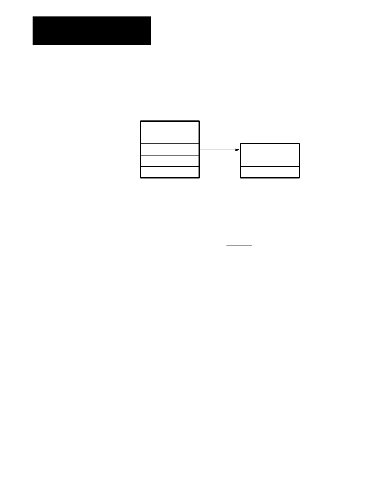
ANALOG OUTPUT Menu The ANALOG OUTPUT menu (see Figure 10.1) allows the analog output
signals to be properly configured. These selections will not become active
until the data has been stored in EEPROM by transitioning the Drive
Enable input from Off to On.
Figure 2.8
Analog Output Menu Tree
ANALOG OUTPUT
Output #1
Output #2
Output #1
This parameter allows Analog Output #1 to be configured for the desired
output parameter.
Possible Choices | MOTOR RPM | (Absolute Value)
MOTOR RPM (Bipolar Value)
| SPINDLE RPM | (Absolute Value)
SPINDLE RPM (Bipolar Value)
% LOAD
% TORQUE
POWER
ORIENT ERROR
Default Value | MOTOR RPM | (Absolute Value)
Output #2
This parameter allows Analog Output #2 to be configured for the desired
output parameter.
Possible Choices | MOTOR RPM | (Absolute Value)
MOTOR RPM (Bipolar Value)
| SPINDLE RPM | (Absolute Value)
SPINDLE RPM (Bipolar Value)
% LOAD
% TORQUE
POWER
ORIENT ERROR
Default Value % LOAD
2-32
Page 36

Chapter
3
Drive Tuning
Chapter Objectives Chapter 3 provides details of the principles and process of tuning the 8510
drive for optimum operation. This chapter is designed to help the user
understand the tuning process and anticipate the results of changes in
tuning parameters. In addition, the Per Unit system of measure is explained
in detail.
Tuning Introduction The purpose of tuning a drive is to achieve the required stability,
bandwidth, and stiffness. Stability is the ability of the drive to regulate
speed or position without oscillation or excessive overshoot. Bandwidth is
related to the quickness of drive response to changing commands. Stiffness
is the ability of the drive to resist external load disturbances.
Tuning closed loop feedback systems can be complicated. There is
however, an organized approach for the typical machine tool as described
below.
• P Gain is strongly related to bandwidth
• I Gain is strongly related to stiffness
• Both P and I Gains are related to stability, if either is too high, the
system will be unstable
When building identical machines in a production environment, only the
first machine should require tuning. All others should perform identically
by simply presetting the parameter values determined while tuning the first
machine.
Tuning Requirements The 8510 drive provides multiple parameter sets to allow optimum
performance to be achieved with multi-speed gearboxes, dual winding
motors, and widely varying operating conditions. Each parameter set
provides unique tuning parameters for spindle, high speed servo, low speed
servo, and spindle orient modes. Each parameter set and its respective
operating modes used in the application will require individual tuning
according to the following procedure. For best results, it is recommended
that an oscilloscope be used to observe the results of drive tuning, however,
acceptable results can often be achieved by simply observing the spindle
and listening to the drive and motor during the tuning process.
3-33
Page 37

Chapter 3
Drive Tuning
Spindle/Servo Mode Tuning The following steps describe the tuning process for spindle or servo mode.
ATTENTION: If an oscilloscope is used during start-up, tuning
!
o 1. Program the following parameters (for the mode you are using) as
or troubleshooting, it must be properly grounded. The
oscilloscope chassis may be at a potentially fatal voltage if not
properly grounded. Always connect the oscilloscope chassis to
earth ground.
When using an oscilloscope it is recommended that the test
probe ground be connected to the test point labeled “GND.”
follows (refer to Chapter 2 as necessary) :
P Gain (Servo or Spindl) – set to the default value (5.0)
I Gain (Servo or Spindl) – set to zero
o 2. Program ANALOG OUTPUT – Output #1 for “± MOTOR RPM” and
ANALOG OUTPUT – Output #2 for “% TORQUE.” While observing
the motor rpm and per cent torque via the analog outputs or test
points, adjust P Gain to achieve the desired speed of response with no
more than one overshoot.
Ideally, P Gain should be adjusted with minimum load inertia. Tuning
with maximum load inertia could result in instability with a smaller
load inertia. Lost motion between the motor and load may
intermittently decouple the load inertia from the motor. This situation
could also lead to instability if the drive were tuned for maximum
inertia.
Lowering P Gain slows response, reduces overshoot, improves
stability, and reduces torque ripple. P Gain should not be increased
beyond the required amount for acceptable system response. Too high
of a P Gain setting will amplify digital and analog system noise and
increase velocity and torque ripple. High torque ripple can overheat
the motor and deteriorate surface finish. If P Gain is increased to
extremes, the system will become unstable, oscillate at a high
frequency, and produce significant audible noise.
It will not be possible to achieve high bandwidth on high inertia
systems. The high P Gain required will cause very high torque ripple
due to digital noise amplification.
3-34
o 3. Increase I Gain to achieve the required stiffness. Ideally, I Gain
should be adjusted with maximum load inertia. Tuning with minimum
load inertia could result in an underdamped response or instability
when larger load inertia is applied.
Page 38

Chapter 3
Drive Tuning
Operating the system in its normal metal cutting mode provides a
simplified method to verify stiffness. Load changes occur due to
milling cutter tooth frequency, intermittent cuts, etc. Velocity
disturbance can be observed by monitoring the motor rpm analog
output signal. Proper stiffness can be assumed when the velocity
disturbances are acceptable.
Stiffness can be measured by applying torque to the system when it is
at rest. The shaft will move an amount proportional to the torque.
When torque is removed, the shaft will return to its original position.
Stiffness is the ratio of torque to the angle moved. The greater the
stiffness, the lesser amount a given torque will disturb the shaft
position, and the quicker the system will respond to counteract the
disturbance.
As I Gain is increased, stability will gradually decrease. Frequency of
oscillation will be relatively low and audible noise should be at a
minimum. This suggests another method for adjusting stiffness,
simply increase I Gain until instability is about to occur, then lower
the gain until the system is well damped.
o 4. When operating the 8510 in servo mode in a closed position loop
(such as during C-axis operation or spindle orient), a “stick/slip
hunting” may be observed. Increasing the Droop In Run value can
minimize this.
“Stick/slip hunting” occurs when static friction is significantly higher
than running friction. As the motor approaches the final commanded
position, the position and velocity error decrease until the
commanded torque is less then the running friction. The motion will
then stop. When the system is at zero velocity with a non-zero
position error, the velocity loop integrator will slowly increase the
motor torque until it builds to the point of breaking the static friction
lock and causing the system to move. Once motion starts, friction
immediately drops from the static level to the running level. Since the
torque being generated to overcome static friction is too high for the
lower running friction level, overshoot of the target position may
result. When motion stops in the process of reversing, static friction
again locks the system. The integrator slowly builds up torque in the
opposite direction until it breaks the friction lock and overshoots in
the opposite direction. Hunting now becomes a never ending process,
usually in the range of 0.5 to 2 Hz.
The integral gain compensator has infinite DC gain, meaning that the
smallest position error (velocity command) can be integrated up, to
eventually generate maximum torque. Droop places a limit on DC
gain and creates a threshold below which small position error cannot
generate enough torque to break the static friction lock. The never
ending cycle of stick/slip hunting is broken. Increasing the Droop In
Run parameter setting will increase the level of this threshold.
o 5. Repeat steps 1 through 4 for each gear range, motor winding, and
mode if applicable.
3-35
Page 39

Chapter 3
Drive Tuning
“Per Unit” System Description The units used to express gain are arbitrary. When tuning analog drives by
adjusting potentiometers, units are completely unknown and gain is only an
arbitrary scale on the pot. Thus, it is possible to tune drives without even
knowing the gain units.
With digital drives, parameter values must relate directly to mathematical
or computer models of the system that are implemented in the drive.
Therefore, the units must follow some defined format.
The 8510 uses the Per Unit system. This system is employed for the
following reasons:
– The Per Unit system is independent of any local system of units. Units
do not change among industries or locality.
– The Per Unit system yields gain values which are very similar over a
wide range of motor/drive sizes. Once you become familiar with typical
values for P, I, and Droop gains, nearly the same values can be expected
for a very wide variety of motor/drive sizes.
– The Per Unit system is becoming the worldwide drives industry
standard.
Per Unit System Defined
Unit Velocity, V, is defined as the motor base speed
Unit Torque, T, is defined as the motor peak torque
Unit Inertia, J, is defined as the time to accelerate to Per Unit speed at Per Unit torque
Unit Time, t, is defined as 1 Second
Example 1:
Unit motor speed is defined as base speed. The base speed of a certain
motor is 1500 rpm. How many units of speed is the motor running at when
it is rotating at 6000 rpm?
6000 rpm
1500 rpm
= 4
Note that the Per Unit speed does not have a unit
Example 2:
The peak torque of the same motor is 200 N-m (147.5 lb.-ft.). What is the
Per Unit torque when operating at 50 N-m (36.9)?
50 N-m (36.9 lb.-ft.)
200 N-m (147.5 lb.-
ft.)
= 0.25
Note that the answer is the same with torque
expressed in lb.-ft. or N-m.
3-36
Page 40

Chapter 3
Drive Tuning
Gains
The variables for gain are expressed in Per Unit. Per Unit P, I, and Droop
gains are defined as:
P is defined as T/V (units of torque produced for each unit of velocity error)
I is defined as T/V/s (units of torque change per second for each unit velocity error)
Droop is defined as V/T (units of velocity droop for each unit of torque being produced)
Example 3:
The same 1500 rpm, 200 N-m (147.5 lb.-ft.) motor will be used.
If the velocity error is 0.02 Per Unit and P = 20, what is the Per Unit
torque?
T = P x V = 20 x 0.02 = 0.4 Per Unit Torque
What is the torque expressed in N-m (lb.-ft.)?
Torque
200 N-m (147.5 lb.-
ft.)
= 80 N-m (59.0 lb.-ft.)0.4 =
Spindle Orient Mode Tuning In the Spindle Orient Mode, the 8510 uses the Servo Mode, High Speed
Range parameter settings to control the dynamics of the velocity loop. The
position loop dynamics is controlled by the settings of the ORIENT TUNE
– Orient Speed and ORIENT TUNE – Orient Start parameters.
The actual target position is either preset by the ORIENT TUNE – Preset
Angle parameter or input through the 16 bit digital speed/position inputs.
The actual source of the orient position data is determined by the setting of
the ORIENT TUNE – Position Data parameter.
The ORIENT TUNE – Orient Speed parameter defines the spindle speed
just prior to the start of the final deceleration toward the target position.
The ORIENT TUNE – Orient Start parameter defines the number of
degrees ahead of the target spindle position where the drive begins the final
deceleration to the target position.
When the Orient Command is energized, the spindle is immediately
decelerated to the Orient Speed. When the Orient Start position is reached,
the final deceleration begins. The deceleration to Orient Speed is a simple
velocity ramp without position control. Thus, the spindle may turn as much
as one revolution at Orient Speed before the Orient Start position is
reached.
3-37
Page 41

Chapter 3
Drive Tuning
If plotted as velocity versus position, the final deceleration is a straight line
from the Orient Speed/Orient Start point to the Zero Speed/Target Position
point (see Figure 3.1). The orient position loop gain is essentially the slope
of this curve and is defined as:
The orient position loop gain that is achieved using the default values for
Orient Speed and Orient Start is:
If the velocity or position error were plotted versus time, the deceleration
would be a single exponential deceleration to the target position.
Figure 3.1
Spindle Orient Operation
Decel from
Running Speed
Kp = 6
Kp = 6
Orient
Speed
x
Orient Start
60 rpm
45.0 degrees
x
(expressed as degrees/second/degrees or radians/second)
= 8 radians/second
Orient Speed
Spindle
Speed
Spindle Position
Begin Final
Deceleration
Slope x 6 = Kp
Final Decel
Orient Start
Target
Position
3-38
Page 42

Chapter 3
Drive Tuning
Spindle Orient Tuning Process
During the final deceleration toward the target position, the drive should
not be in torque limit. When the drive is in torque limit, the actual spindle
position will fall behind the commanded spindle position, and the system is
likely to overshoot the target position as the control loops try to recover.
The peak torque required from the drive to decelerate the spindle is directly
related to the total system inertia, the orient position loop gain (Kp), and
the motor speed when the deceleration is initiated.
Please note the following points:
- For any setting of Orient Speed, the required peak torque will increase in
direct proportion to the increase in Kp (Orient Start setting is decreased).
- For any specific value of Kp (ratio of Orient Speed to Orient Start), the
required peak torque will increase in direct proportion to the increase in
value of Orient Speed.
- For any setting of Orient Start, the required peak torque will increase as
the square
of any percentage increase in the Orient Speed parameter
value. For example, if the Orient Speed is increased from 100 to 200
rpm, the peak torque will increase to 400% of the previous value.
Increasing Orient Speed without changing Orient Start increases both
the value of Kp and the initial decel speed.
The time to perform the spindle orient is composed of three components:
1. the time to decelerate to the Orient Speed,
2. the time to search for the Orient Start spindle position, and
3. the time for the final deceleration to the target position.
The initial time to decelerate to the Orient Speed is determined by the
actual spindle speed when the orient command is given and is not
controllable by drive tuning. The time required to search for the Orient
Start position can be minimized by increasing the setting of Orient Speed
as much as possible, without causing the drive to be torque limited. The
time for the final deceleration is minimized by increasing the value of Kp
as much as possible. After selecting the Orient Speed, the Orient Start
setting is made as small as possible without forcing the drive into torque
limit, which will result in the highest possible setting of Kp.
On a high inertia spindle, if the Orient Speed is set too high, the orient
position loop gain (Kp), may have to be very low to prevent the drive from
going into torque limit. This low Kp setting may lengthen the deceleration
time, offsetting any reduction in the time spent searching for the Orient
Start position achieved by using the high Orient Speed setting. Quicker
orient performance may be obtained by reducing the Orient Speed setting
and increasing the Kp value.
In a typical system, the orient position loop gain (Kp), should be between 5
and 20 radians/second. Lower gains are usually used with gearboxes and
high inertia systems. Higher gains can be used with direct drive and low
inertia systems.
3-39
Page 43

Chapter 3
Drive Tuning
Spindle orient tuning should be adjusted with the maximum expected load
inertia connected to the system, if possible. If this is not possible, estimate
the maximum expected load inertia versus the current value of load inertia.
Reduce the maximum allowed peak torque during the spindle orient tuning
by this ratio. For example, if the worst case load inertia would be about
twice the system inertia during setup, adjust the Orient Speed and Orient
Start parameters to require no more than one half the drive peak torque
capability during setup.
Orient Tuning Procedure
o 1. Verify proper orient operation using the default values for Orient
Speed and Orient Start.
o 2. Program ANALOG OUTPUT – Output #1 for “± MOTOR RPM” and
ANALOG OUTPUT – Output #2 for “% TORQUE.” Use an
oscilloscope to monitor the % Torque during orient.
If the system can be tested with the maximum expected load inertia
connected, the peak torque during decel should not exceed 95% of
maximum capability (9.5 volts on Analog Output #2). If the system is
being setup without a workpiece or tooling installed, the
recommended maximum torque value is 40% of peak torque
capability (4 volts output) for a lathe and 70% of peak torque
capability (7 volts output) for a machining center. For systems with a
completely known and repeatable load inertia and torque requirement,
a small amount of torque limiting is acceptable and will usually
shorten the time to decelerate to the target position.
3-40
o 3. Observe the peak torque required when using the default values of
Orient Speed and Orient Start. Compare this observed peak torque
with the desired peak torque defined above to determine the necessary
adjustments to the Orient Speed and Orient Start settings. For
example, if the observed peak torque was 25% of the target value,
then potential actions are to:
- Increase Orient Speed setting from 60 to 240 rpm and Orient Start
from 45 to 180 degrees (maintain Kp at 8 radians/second while
raising Orient Speed a factor of 4), or
- Reduce Orient Start from 45 degrees to 11.25 degrees without
changing Orient Speed setting (quadruple Kp from 8 to 32 radians/
second with the same Orient Speed), or
- Increase Orient Speed setting from 60 to 120 rpm without changing
Orient Start setting (double Kp to 16 radians/second and double the
Orient Speed).
o 4. Adjust Orient Speed and Orient Start to give desired levels of peak
torque during orient. Assure that the spindle does not overshoot target
position by viewing actual spindle motion and observing ±MOTOR
RPM and % TORQUE analog outputs with the oscilloscope. If
position overshoot occurs, increase value of Orient Start to reduce
Kp.
Page 44

Appendix
A
Parameter Record
Introduction The following list can be used to record final parameter values for
reference at a later date. It is recommended that any changes made to the
parameter values be recorded.
Machine Designation
Location
Date
Name
General Information
Menu 1 Menu 2 Parameter
GEAR RANGES SET RATIOS Spindle Revs
Motor Revs
MOTOR SELECT
Catalog Num
PARAMETER SET ELECT
CONFIG Drive Cat Num
Motor Phasing
Cmnd Phase #1
Cmnd Phase #2
Enable Torque
SPINDL PRESETOverspd Trip
Acc Rate #1
Acc Rate #2
Low Torq Lmt
At-Set-Speed
Speed Detect
Load Detect
1 or 1L 1H 2 or 2L 2H 3 or 3L 3H 4
A-41
Page 45

Appendix A
Parameter Record
Menu 1 Menu 2 Parameter
DRIVE TUNING SPINDLE MODE Cmnd Source
Max Cmnd Spd
Spindl P Gain
Spindl I Gain
Speed Cal
ANALOG CAL Zero Volt In
Max +Volt In
SERVO MODE Analog In #
A/D Conv Type
ANALOG CAL Zero Volt In
Max +Volt In
HI SPD RANGE Max Cmnd Spd
Servo P Gain
Servo I Gain
Droop In Run
Droop In Hold
Speed Cal
LO SPD RANGE Max Cmnd Spd
Servo P Gain
Servo I Gain
Droop In Run
Speed Cal
TORQUE MODE Torque Enable
Max Speed
ANALOG CAL Zero Volt In
Max +Volt In
ORIENT SETUP FEEDBACK DEFN
Encoder Type
Encoder Lines
Encdr Phasing
ORIENT TUNE Position Data
Preset Angle
Orient Speed
Orient Start
In-Position
Dir From Stop
Hold Psition
ANALOG OUTPUT
A-42
Output #1
Output #2
1 or 1L 1H 2 or 2L 2H 3 or 3L 3H 4
Page 46

IBM is a registered trademark of International Business Machines Corporation.
Page 47

Publication 8510-5.2 – August, 1993 P/N152825
Supersedes May, 1993 Copyright 1993 Rockwell International Corporation. All rights reserved. Printed in USA
 Loading...