

Page 1

ALLEN-BRADLEY
8510 AC Spindle Drive
Connector Kits
(Cat. No. 8510SA-C20S, 8510SA-C50S)
Instructions
Introduction All signal interface connections to the 8510 AC Spindle Drive are made
through Honda MR series connectors. This publication will provide the
information needed to properly install these connectors.
The interface function and the connector kit required are shown below:
Interface Function Connector Kit
Standard Digital and Analog I/O 8510SA–C50S
Resolver Feedback from Motor 8510SA–C20S
Digital Speed/Position Input 8510SA–C20S
Position Feedback for Spindle Orient 8510SA–C20S
Dual Winding Motor Control 8510SA–C20S
Refer to the 8510 User Manual, publication 8510-5.1 for detailed
information about the cable required and the connector pin assignments for
each of the above interfaces.
Assembling the Connector/Cable The following procedure outlines the steps needed to install the connector.
1. Verify that the connector kit includes the blue connector body and the
gray housing (see Figure 1).
2. Refer to the 8510 User Manual to determine the required cable type and
connector pin assignments for each interface function. The maximum
wire size that the connector terminals can accept is 24 AWG
(0.283 mm
3. Disassemble the connector by removing the 2 short screws and nuts
(see Figure 1). Since the connector contains a number of small pieces,
care should be taken during disassembly.
2
).
4. Prepare the cable and wire ends. The connector shell is relatively short,
so minimize the amount of cable insulation that is removed (or it may
be difficult to properly clamp the cable into the connector shell).
Carefully solder the wires to the connector pins with a rosin core
solder. The connector pin designations are shown in Figure 1.
5. Install cable clamp around cable(s). To allow positioning, do not
tighten clamp completely.
Page 2
Instructions
8510 Connector Kits
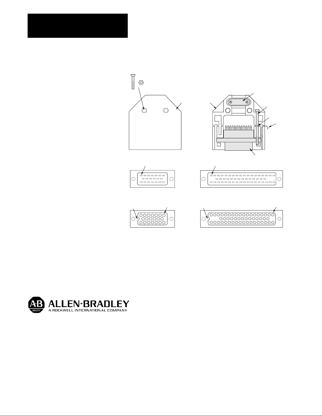
Figure 1
Connector Assembly
Short Screw & Nut
Pin 1
Cable Clamp
Connector Housing
Long Screw
Washer
Clip
Connector Body
Pin 1
Back Side of 20 Pin Connector
Locating Notch
Front Side of 20 Pin Connector
6. Place connector body into housing and slide cable clamp to position
shown. Tighten cable clamp.
7. Re-install the 2 long screws/washers, clips and assemble the connector
housing as shown in Figure 1.
With offices in major cities worldwide.
1
8
14
HONDA
1
19
33
HONDA
Back Side of 50 Pin Connector
Pin 1
Locating Notch
Pin 1
Front Side of 50 Pin Connector
Allen-Bradley has been helping its customers improve productivity and quality for 90 years.
Allen-Bradley designs, manufactures and supports a broad range of control and automation
products worldwide. They include logic processors, power and motion control devices,
man-machine interfaces and sensors. Allen-Bradley is a subsidiary of Rockwell
International, one of the world’s leading technology companies.
WORLD
HEADQUARTERS
Allen-Bradley
1201 South Second Street
Milwaukee, WI 53204
USA
Tel: (1) 414 382-2000
Telex: 43 11 016
Fax: (1) 414 382-4444
Publication 8510-5.11 – April, 1993 P/N 152821
EUROPE/MIDDLE
EAST/
AFRICA
HEADQUARTERS
Allen-Bradley Europe
B.V.
Amsterdamseweg 15
1422 AC Uithoorn
The Netherlands
Tel: (31) 2975/43500
Telex: (844) 18042
Fax: (31) 2975/60222
ASIA/PACIFIC
HEADQUARTERS
Allen-Bradley (Hong Kong)
Limited
Room 1006, Block B, Sea View
Estate
2-8 Watson Road
Hong Kong
Tel: (852) 887-4788
Telex: (780) 64347
Fax: (852) 510-9436
CANADA
HEADQUARTERS
Allen-Bradley Canada
Limited
135 Dundas Street
Cambridge, Ontario N1R
5X1
Canada
Tel: (1) 519 623-1810
Fax: (1) 519 623-8930
Copyright 1993 Allen-Bradley Company, Inc. Printed in USA
LATIN AMERICA
HEADQUARTERS
Allen-Bradley
1201 South Second
Street
Milwaukee, WI 53204
USA
Tel: (1) 414 382-2000
Telex: 43 11 016
Fax: (1) 414 382-2400
 Loading...