

Page 1
Installation Instructions
IMPORTANT: SAVE THESE INSTRUCTIONS FOR FUTURE USE.
847
A
a
-
Q
b
c
e
-
65536
31 4 R B
dfgh
847A and 847B Hollow Shaft Incremental Encoders
Selection Guide
a
Code Encoder Diameter/Type
A 2 in. diameter, blind hollow shaft
B 2 in. diameter, through hollow shaft
b
Code Mounting Configuration
Q
R
3-point mounting
2-point mounting
c
Code Shaft Size
3 3/8 in. diameter metal hollow shaft
4 1/2 in. diameter metal hollow shaft
e
Code Output Configuration
Signal Phasing A-leads-B
clockwise rotation viewed from shaft end, Z gated A
4
5
6
7
Signal Phasing B-leads-A
clockwise rotation viewed from shaft end, Z gated BN
A
B
C
D
Options 5 and B cannot be ordered with option 2 from Table d.
Options 6, 7, C, and D cannot be ordered with option 1 from Table d.
4.5…5.5V line driver outputs (TTL)
4.5…5.5V open collector outputs
8…30V line driver outputs (HTL)
8…30V open collector outputs
4.5…5.5V line driver outputs (TTL)
4.5…5.5V open collector outputs
8…30V line driver outputs (HTL)
8…30V open collector outputs
f
Code Connector/Cable Exit
R
Radial exit
d
Code Power Supply
14.5…5.5V DC
28…30V DC
Accessories
Description Part Number
Differential encoder buffer board 845-BB*
M12 cable 889D-F8FB-*
* See Sensor Catalog for selection
g
Code Connector/Cable Type
A
B
P
Q
R
M12 connector, 8-pin with mating connector
M12 connector, 8-pin
1.5 m (4.9 ft) cable
5 m (16.4 ft) cable
10 m (32.8 ft) cable
h
Code Resolution
00001...
65536
00001...65536 pulses/revolution
Page 2
Specifications
Make sure mating shaft is chamfered and
grease-free.
Do not stress the flex mount while tightening
the screws.
Environmental
Electrical
Code format Incremental
Signal options,
clockwise rotation viewed from
shaft end
Signal phase relation 90° ± 22° channels
Symmetry 40…60%
Supply current 50 mA
Frequency response 4.5…5.5V line driver output: 820 kHz
Resolution 1...65536 pulses/revolution
Load current 30 mA for all output types
Output drivers 4.5…5.5V line driver - IC HD2
Electrical protection Reverse polarity and short circuit for
Cable outer diameter 0.25 in (6.2 mm)
Cable type 300V, 105 °C, 26 AWG, 9-conductor
Two channels with zero index
A-leads-B, 180° marker gated with A
or
B-leads-A, 180° marker gated with BN
8…30V line driver output: 820 kHz
Open collector: 150 kHz
8…30V line driver - IC HD2
Open collector - 7406
all output types
with overall braided shield, UL AWM
type 20327 for use in fixed (nonflexing) installations; RoHs compliant.
Enclosure rating per IEC 60529 Shaft: IP 65
Housing, connector version with
mating connector installed:
with blind hollow shaft: IP67
with through hollow shaft: IP65
Housing, cable version:
with blind hollow shaft: IP67
with through hollow shaft: IP65
Temperature -30…80 °C (-22...176 °F) operating
-40…100 °C (-40...212 °F) storage
Relative humidity 90% non-condensing
Shock 100 G/11 ms duration
Vibration 30 G/10…2,000 Hz
EMC EN 61000-6-2 and EN 61000-6-3
(M12 connector)
Housing material EN AC-47100 die-cast aluminium
Housing finish Powder coat paint, color RAL 9005,
Pantone black C (jet black)
Flange material 6061-T6 aluminium
Shaft material SAE 303 stainless steel
Certifications UL Listed, RoHS compliant
CE Marked for all applicable directives
Mounting Instructions
Cable bend radius Minimum 5x outer diameter
Mechanical
Maximum operating speed 6,000 RPM
Angular acceleration 500,000 radians/s²
Moment of inertia 40 g•cm²
Startup torque at 20 °C (68 °F) 0.8 N•cm
Operating torque at 20 °C (68 °F)
Permissible shaft movement
[mm (in.)]
Hollow shaft diameter 3/8 in. (9.5 mm) or 1/2 in. (12.7 mm)
Approximate weight [kg (lb)] 0.16 (0.35) with M12 connector
MTTFd (EN ISO 13849-1) 330 years
0.6 N•cm
Radial
Static: ± 0.3 (0.012)
Dynamic: ± 0.05 (0.002)
Axial
Static: ± 0.5 (0.02)
Dynamic: ± 0.1 (0.004)
IMPORTANT
1. Using a 5/64-in. Allen wrench, loosen the screw on the
clamping ring.
2. Slide the encoder onto the mating shaft until the flex
mount rests on the machine surface.
The encoder should slide freely onto the shaft; if not, do
not force. Check the shaft for interferences such as
gouges, burrs, rust, or size.
If mounting holes already exist, proceed to step 6.
3. Hold encoder firmly and mark the mounting holes.
4. Mount the encoder with #4-40 (or equivalent) screws.
5. Slide the encoder back onto the shaft until the flex
mount rests on the machine surface.
6. Attach the encoder with #4-40 (or equivalent) screws.
IMPORTANT
7. Tighten the clamping ring screw to 8 in-lb.
2
Page 3

8. Make the electrical connections according to the
Wiring must be in accordance with the
National Electric Code and applicable local
codes and regulations.
Measuring step
A leads B, 180°
marker gated with A
Signals and marker option - A leads B (CW rotation)
Clockwise rotation when facing encoder shaft
Measuring step
B leads A, 180°
marker gated with BN
Signals and marker option - B leads A (CW rotation)
Clockwise rotation when facing encoder shaft
Connector Pins and Signal Availability table.
IMPORTANT
Output Waveforms
Complementary signals AN, BN, and ZN are supplied only
on units with line driver outputs.
Connector Pins and Signal Availability
Wire color
Signal Name
V DC Red 8
Common Black with red band 7
A output White 2
AN output Black with white band 1
B output Blue 4
BN output Black with blue band 3
Z output Green 6
ZN output Black with green band 5
Zero set input Yellow –
Case Black –
Recommended
mating cable
attached cable
M12 8-pin connector
(Attached to encoder) 889D-F8FB-*
5
6
8
4
Pin number
90°
360°
A
B
Z
90°
360°
A
B
7
1
M12 pins
on encoder connector
3
2
Z
3
Page 4
Power, Control and Information Solutions Headquarters
Americas: Rockwell Automation, 1201 South Second Street, Milwaukee, WI 53204-2496 USA, Tel: (1) 414.382.2000, Fax: (1) 414.382.4444
Europe/Middle East/Africa: Rockwell Automation NV, Pegasus Park, De Kleetlaan 12a, 1831 Diegem, Belgium, Tel: (32) 2 663 0600, Fax: (32) 2 663 0640
Asia Pacic: Rockwell Automation, Level 14, Core F, Cyberport 3, 100 Cyberport Road, Hong Kong, Tel: (852) 2887 4788, Fax: (852) 2508 1846
www.rockwel lautomation.com
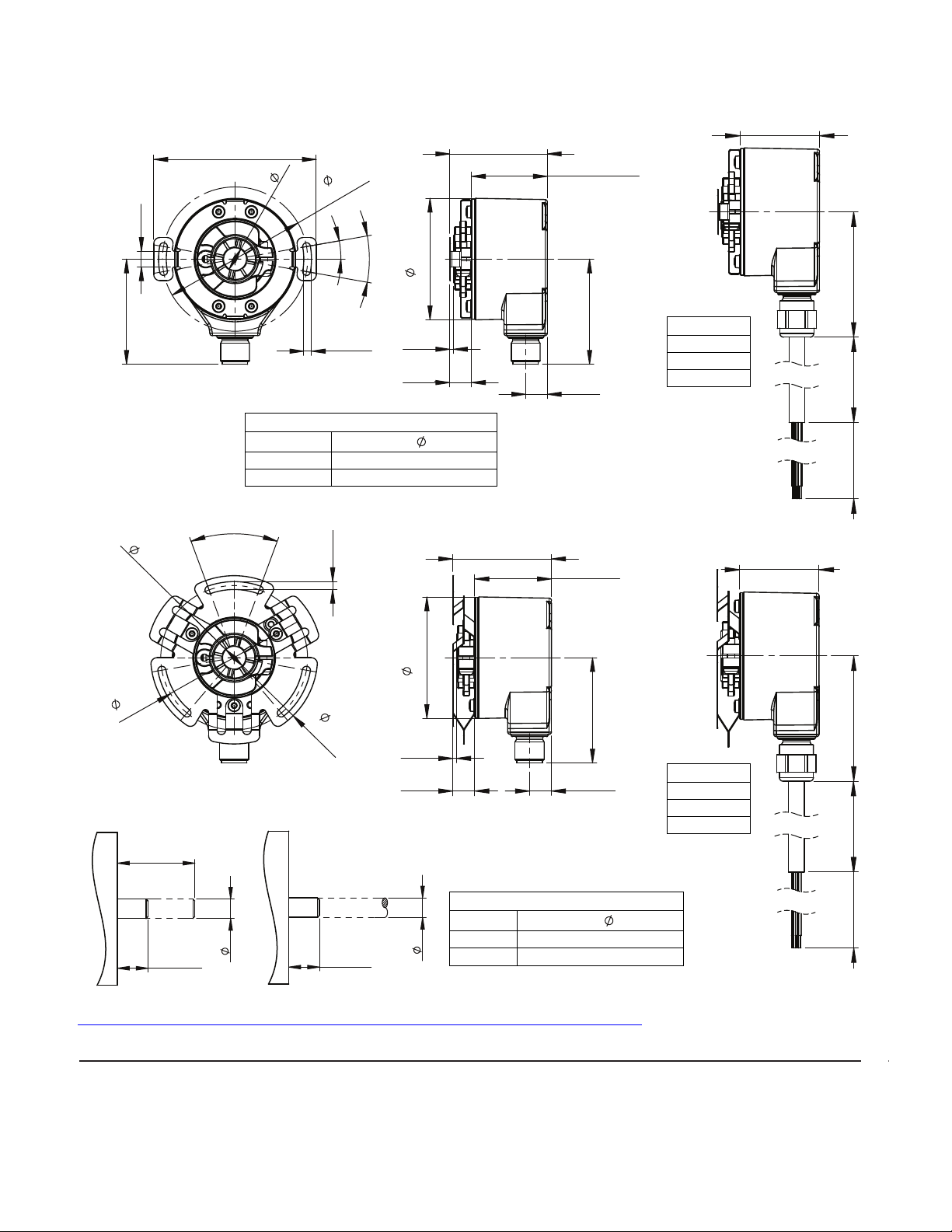
Dimensions [mm (in.)]
15
(0.59)
MIN
X
Cable options
1.5 m (4.9 ft)
5 m (16.4 ft)
10 m (32.8 ft)
847A and 847B customer shaft diameter
Nominal, in.
Shaft X
3/8 9.535...9.520 (0.3754...0.3748)
1/2 12.712...12.694 (0.5005...0.4998)
847A blind hollow shaft 847B through hollow shaft
2-Point Mounting
3-Point Mounting
A
60.3
(2.38)
68.6
(2.70)
3 x 40°
3 x
3.3
(0.13)
1.53
(0.06)
9
(0.35)
50.8
(2.00)
44
(1.73)
9
(0.35)
847A: 31.5 (1.24)
847B: 29.5 (1.16)
847A: 40.5 (1.59)
847B: 38.5 (1.52)
Customer Shafts
847A and 847B bore diameter options
Nominal, in.
Bore A
3/8 9.543...9.558 (0.3757...0.3763)
1/2 12.716...12.734 (0.5006...0.5013)
Cable options
1.5 m (4.9 ft)
5 m (16.4 ft)
10 m (32.8 ft)
67.5
(2.66)
6.5
(0.26)
847A: 31.5 (1.24)
847A: 40.5 (1.59)
847B: 38.5 (1.52)
A
60.3
(2.38)
847A: 31.5 (1.24)
847B: 29.5 (1.16)
847B: 29.5 (1.16)
44
(1.73)
10°
3.2
(0.13)
20°
50.8
1.53
(0.06)
9
(0.35)
(2.00)
44
9
(0.35)
(1.73)
847A: 31.5 (1.24)
847B: 29.5 (1.16)
49.73
(1.96)
NUMBER
PER PART
50
(1.97)
38
MAX
(1.50)
X
Rockwell Automation maintains current product environmental information on its website at
http//www.rockwellautomation.com/rockwellautomation/about-us/sustainability-ethics/product-environmental-compliance.page
Copyright © 2014 Rockwell Automation, Inc. All rights reserved. 10001065808 Ver 00 July 2014
15
(0.59)
MIN
.
49.73
(1.96)
NUMBER
PER PART
50
(1.97)
847AB-IN001A-EN-P
Printed in USA
 Loading...