

Page 1
Obsolete
Installation Instructions
Size 25 Incremental Encoder, Bulletin 845S
IMPORTANT: SAVE THESE INSTRUCTIONS FOR FUTURE USE.
Specifications
Electrical
Code Format Incremental, 2 channels with zero index
Quadrature 90° ±22°, Channel A leads B CCW
Symmetry 50% ±10%
Zero Index Channel 1/2 cycle, gated to channel B
Power
Requirements
Frequency
Response
Operating Speed
Resolution Up to 5000 PPR on code disk
Output Drive
Capability
Mechanical
Starting &
Running Torque
Moment of Inertia 15gcm2 (2.1 x 10Ć4ozĆinĆsec2)
Slew Speed 6000 RPM
Shaft Loading
(3/8I & 10mm Dia.)
Shaft Size 6mm, 10mm, 6.4mm (1/4in) 9.517mm (3/8in) diameter
Environmental
Housing NEMA Type 4, 13, IP66 (IEC 529)
Temperature 0°C to +60°C (+32°F to +140°F)Ċoperating
Humidity 98%, noncondensing
Vibration 20g (58 to 2000Hz), 1.5mm displacement (5 to 58Hz)
Approximate
Shipping Weight
Determined by catalog number:
5V DC ±5% @ 150mA maximum
8-24V DC @ 150mA maximum
Data: 100kHz
Zero index: 100kHz
(100kHz x 60)/pulses per revolution = RPM or
(Data)
6000 RPM, whichever is lower
Differential line driver = ±20mA
2.5Ncm typical (3.5inĆoz)
Axial 89N (20lbs) (10lbs 5000 PPR)
Radial 178N (40lbs) (20lbs 5000 PPR)
-25°C to +90°C (-13°F to +194°F)Ċstorage
Shock 50g (11ms duration)
0.91kg (2lbs)
Accessories
Description Part Number
High Performance Flexible Coupling 845-FC-*-*
Measuring Wheels 845-MW-A-*
Servo Clamps 845-SC
PreĆWired Cables 845-CA-K-*
Mating Connectors 845-10P
Differential Encoder Buffer Board 845-BB
*See the Sensors catalog for selection.
ATTENTION: The shielded cables, output devices,
and power supplies must be properly grounded. All
National Electric Code and applicable local codes
and ordinances must be observed when wiring the
system.
Selection
845S — S J H Z 1 4 CR Y 2 C
a b c d e f g
a
Mounting
Configuration
Code Description
Square FlangeD
E 70mm Diameter Flange
90mm Diameter FlangeF
G Metric Servo 48mm B.C.
English ServoH
J Metric Servo 42mm B.C.
b
Shaft Options Ê
Code Description
A
B 10mm Diameter
Z 3/8in Diameter
L 10mm w/Flat
M 1/4in w/Flat
6mm Diameter
1/4in DiameterC
6mm w/FlatK
3/8in w/FlatN
3/8in w/Double FlatP
c
Power Supply
Code Description
5V DC ±5%1
2
8-24V DC Unregulated
Code Description (PPR)
CB 60
DB 120
CC 254
CK 360
DW 512
CD 1250
RF 1280
CU 1472
DN
HL 2400
CT 3600
e
Resolution
50CA
64CE
80CF
100CG
180EB
200CH
250CJ
256CW
300EG
400CL
500CM
600EH
900LG
1000CN
1024FW
1200EL
1600FL
1800CP
2000
2048CS
2500CR
2540CY
5000DR
d
Output Configuration Ë
Code Description
DLD 5V DC RS-4224
6
Ê Standard catalog numbers consist
of either English Mounting
Configurations with English Shaft
Options or Metric Mounting
Configurations with Metric Shaft
Options.
Ë DLD = Differential Line Driver
Ì Can not be ordered with 5V DC
power supply (code 1 above)
Î These options not available with
Connection Options code: “A” & “R.”
Ï These options not available with
Connection Options code: “1” & “2.”
DLD 8-24V DC Ì
Connection Options
Code Description
2 Radial Connector (Side)
R Radial Cable (Side)
Connector Options
Code Description
Blank
C
1
5
9
f
Axial Connector (End)1
Axial Cable (End)A
g
Without Mating Connector Î
With Mating Connector Î
1m (3.28ft) Cable Length Ï
5m (16.4ft) Cable Length Ï
9m (29.52ft) Cable Length Ï
Page 2
Obsolete
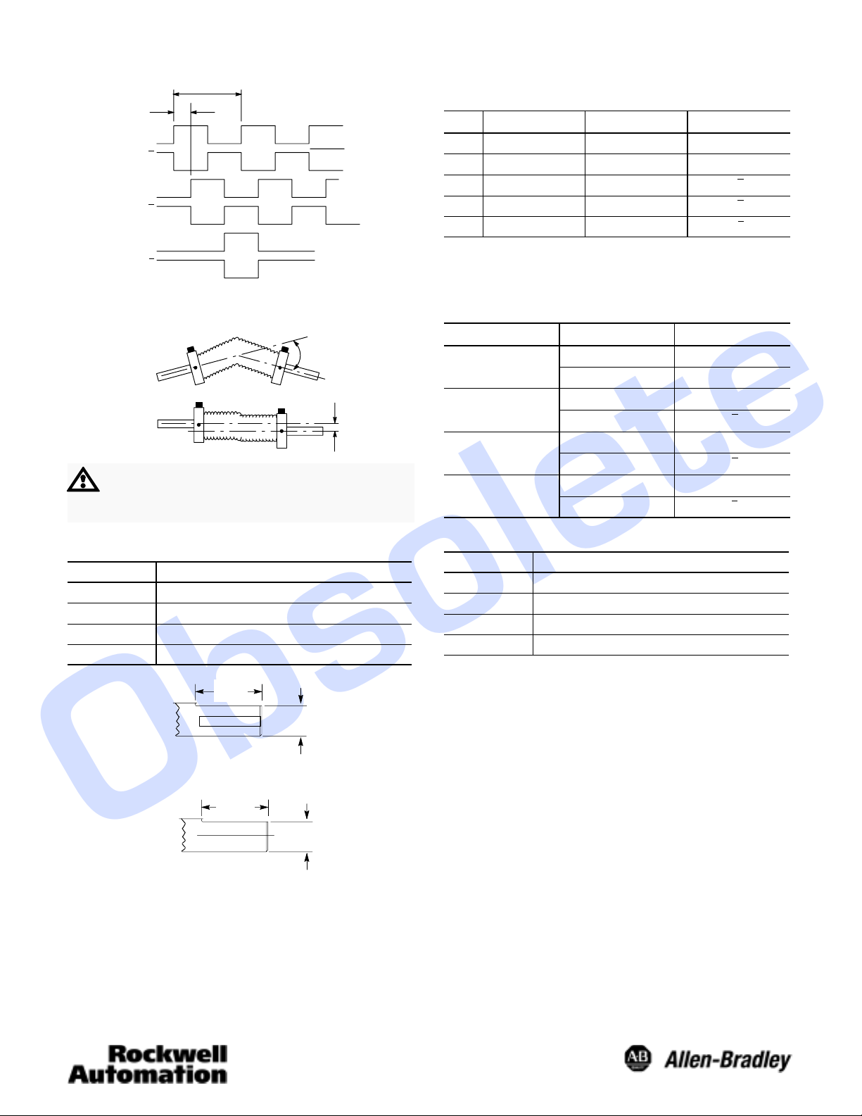
Differential Line Driver Output Waveform:
1 Cycle
90 +/- 22°
Channel A
Channel A
Channel B
Channel B
(Index)Channel Z
Channel Z
Flexible Shaft Couplings
ATTENTION: Rigidly coupling the encoder shaft
to the machine shaft will cause a failure in either
the bearings of the encoder or the bearings of the
machine shaft.
Shaft Diameter Options
Code Shaft Diameter
A or K 6mm +0.00mm, -0.013mm
B or L 10mm +0.00mm, -0.013mm
C or M 6.35 (0.2499) +0.0000, -0.0005
Z or N 9.52 (0.3749) +0.0000, -0.0005
(CCW Rotation Shown)
Angle
Parallel
OffĆSet
Logic 1
Logic 0
10-Pin Connector ACS02E18–1P (023) or Equivalent
Differential LineĆDriver Outputs
Pin
A Channel A Output F DC Return
B Channel B Output G
C Channel Z Output H Channel A Output
DÊ
EÊ
Ê Pins D and E internally connected
Ë Pins G not connected to case ground.
Cable
Differential Line Driver Outputs
Function Pin Function
DC+ Input I Channel B Output
Ċ J Channel Z Output
Wire Pair
Red/Black
White/Black
Blue/Black
Green/Black
Wire Color Function
Red DC+ Input
Black DC Return
White Channel A Output
Black Channel A Output
Blue Channel B Output
Black Channel B Output
Green Channel Z Output
Black Channel Z Output
Shield Ë
Flat Dimensions
Code Dimension A"
K 5.3mm (0.21in)
L 9.1mm (0.36in)
M 5.5mm (0.22in)
N 8.6mm (0.34in)
18.3
(0.72)
9.1
(0.36)
3/8I Dia. Double Flat
Shaft
19.05
(0.75)
A
Shaft with Flat Option
Page 3

Obsolete
Dimensions—inches (mm)
Axial Mount
Connector
63.5
(2.50)
7.62
(0.300)
See Table on bottom
of page NO TAG.
26.21
(1.032)
26.21
(1.032)
52.40
(2.063)
52.40
(2.063)
Axial Mount
Connector
66.5
(2.62)
Sq.
Square Flange Mount
73.9
(2.91)
73.9
(2.91)
Radial Mount
6.35 (0.25)
21.59/22.86
(0.85/0.90)
31.75
(1.250) Dia.
5 (0.21) Dia.Ċ
4 Mounting Holes
8-32 UNCĆ2B x 4.6 (0.18)
Deep on a 47.6(1.875) Dia.
Connector
Bolt Circle,
3 PlacesĊ120° Apart
Axial Mount
Connector
68.3
3.05
20.0
See Table on bottom
of page NO TAG.
Axial Mount
Connector
70.0
Dia.
73.9
(2.91)
73.9
(2.91)
6.35
31.75 Dia.
Axial Mount
Connector
68.3
Radial Mount
Connector
M4 x 5.0 Deep on a
70.0 Dia. Bolt Circle,
4 PlacesĊ90° Apart
M4 x 5.0 Deep on
a 64.0 Dia. Bolt
Circle, 4 PlacesĊ
Metric Flange Mount
20.0
90° Apart
3.05
31.75 Dia.
Axial Mount
Connector
90.0
Dia.
73.9
(2.91)
Radial Mount
Connector
6.35
See Table on bottom
of page NO TAG.
73.9
(2.91)
63.5
(2.50)
7.62 (0.300)
See Table on bottom
of page NO TAG.
58.67 (2.31) Dia.
63.50
(2.500) Dia.
8-32 UNCĆ2B x 4.6 (0.18)
Deep on a 47.6 (1.875)
Dia. Bolt Circle,
3 PlacesĊ120° Apart
Connector Type
Output Code Output Type Connector Type Number of Pins
65
(2.56) Dia.
English Servo Mount
Radial Mount
Connector
2.54 (0.100)
21.59/22.86 (0.85/0.90)
31.75
(1.250) Dia.
2.54 (0.100)
63.5
8.0
See Table on botĆ
tom of page
NO TAG.
58.67 Dia.
63.50 Dia.
65.0
(2.56) Dia.
Radial Mount
Connector
2.54
2.54
20.0
31.75 Dia.
M4 x 5.0 Deep on a
42.0 Dia. Bolt Circle
3 PlacesĊ120° Apart
Metric Servo Mount
63.5
8.0
31.75 Dia.
58.67 Dia.
63.50 Dia.
65.0
(2.56)
Dia.
2.54
20.0
See Table on bottom
of page NO TAG.
M3 x 5.0 Deep on a
48.0 Dia. Bolt Circle,
3 PlacesĊ120° Apart
4 Diff. Line Driver ACS02E18-1P (023) 10
Radial Mount
Connector
2.54
Page 4

Obsolete
Publication 75008–159–01(A)
June 2001
Printed in USA
 Loading...