

Page 1
Installation Instructions
Size 20 Digital Tachometer, Bulletin 845PY
IMPORTANT: SAVE THESE INSTRUCTIONS FOR FUTURE USE.
Specifications
Electrical
Code Format Incremental, 2 channels
Quadrature 90° ±22°
Symmetry 50% ±10%
Requirements
Frequency
Response
Operating Speed (100kHz x 60)/pulses per revolution = RPM or
Resolution Up to 3000 PPR on code disk
Output Drive
Capability
Channel A leads B CCW
Power
Determined by catalog number:
5V DC ±5% @ 150mA maximum
11-20V DC @ 150mA maximum
24V DC @ 150mA maximum
210kHz
15,000 RPM, whichever is lower
Differential line driver = ±20mA
Mechanical
Starting Torque 2.5 Ncm typical (3.5inĆoz)
Running Torque 2.5 Ncm typical (3.5inĆoz)
Slew Speed 15,000 RPM
Shaft Loading Axial: 359N (80lbs)
Shaft Size 7.94mm (5/16in) diameter
Radial: 222N (50lbs)
Environmental
Housing NEMA Type 4, IP66 (IEC 529)
Temperature 0°C to +60°C (+32°F to +140°F) Ċ operating
Humidity 98%, noncondensing
Vibration 20g (5 to 2000Hz)
Approximate
Shipping Weight
-25°C to +90°C (-13°F to +194°F) Ċ storage
Shock 50g (11ms duration)
0.56kg (20oz)
Accessories
Description Part Number
PreĆWired Cables 845-CA-PY-*
Mating Connectors 845-10P, 845-10P-RT
Differential Encoder Buffer Board 845-BB
Selection
845PY — FW — 2—C
a b c
ab
Resolution Power Supply Optiontor
Code Description Code Description
AM 5 1 5V DC ±5%
BG 10 2 11-20V DC
CA 50 3 24V DC ±10%
CB 60
CE 64
CF 80
CG 100 Code
DB 120 Blank Without Mating Connector
DF 150 C With Mating Connector
EB 180
CH 200
CJ 250
CC 254
CW 256
EG 300
CK 360
CL 400
CM 500
DW 512
EH 600
DG 720
DL 800
LG 900
CN 1000
FW 1024
EL 1200
CD 1250
RF 1280
CU 1472
EM 1500
FL 1600
CP 1800
DN 2000
CS 2048
HL 2400
CR 2500
CY 2540
LJ 2750
EN 3000
Mating Connector
c
Description
Page 2
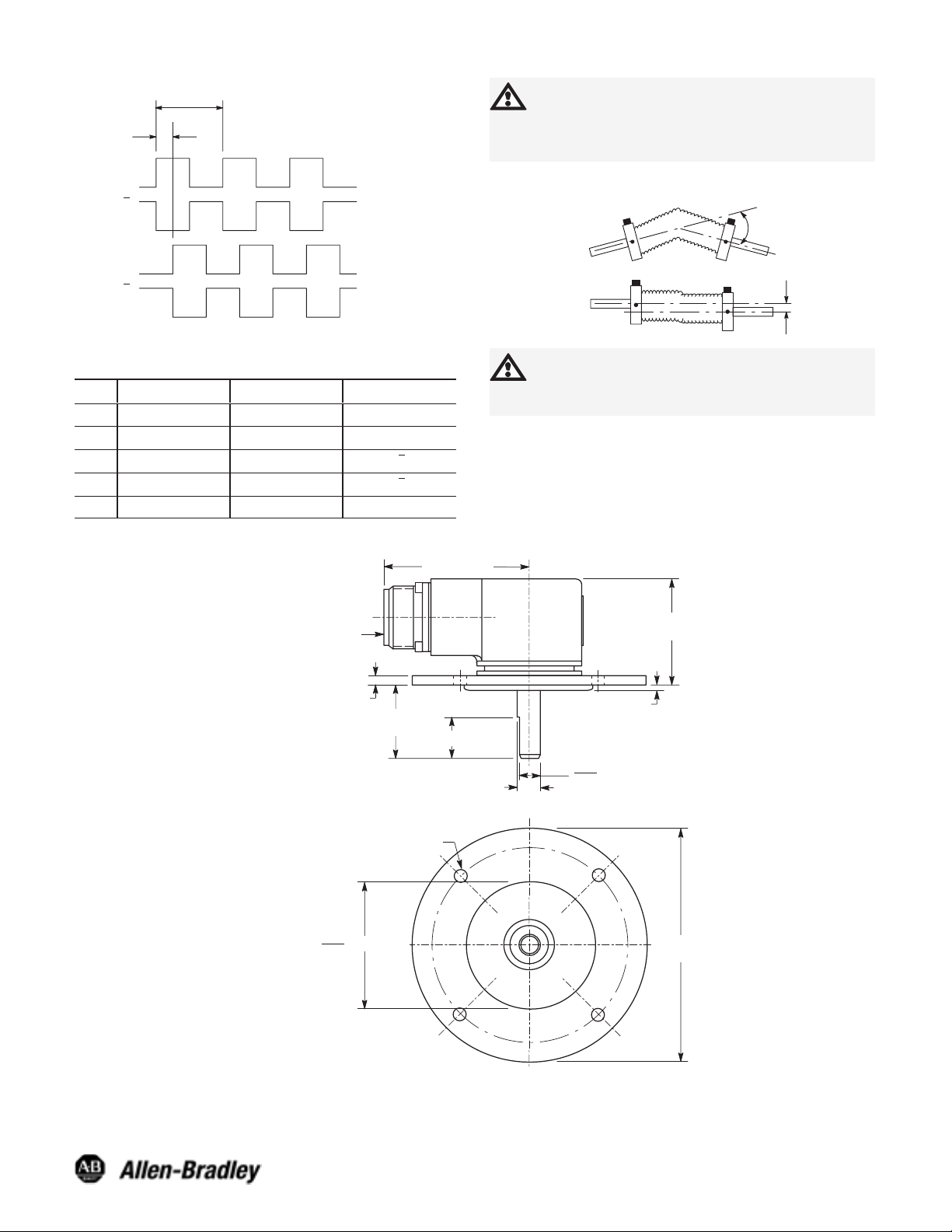
Differential Line Driver Output
90 +/- 22°
1 Cycle
ATTENTION: The shielded cables, output devices,
and power supplies must be properly grounded. All
National Electric Code and applicable local codes
and ordinances must be observed when wiring the
system.
Channel A
Channel A
Channel B
Channel B
(CCW Rotation Shown)
10-Pin Connector (ACS02E18S–1P (023))
Differential Line Driver Outputs
Pin
A Channel A Output F DC Return
B Channel B Output G No Connection
C No Connection H Channel A Output
D DC+ Input I Channel B Output
E No Connection J No Connection
Function Pin Function
Dimensions (Approximate)—mm (inches)
Radial Connector:
10ĆPin (ACS02E18-1P)
69 (2.73) Max.
Flexible Shaft Couplings
ATTENTION: Rigidly coupling the encoder shaft
to the machine shaft will cause a failure in either
the bearings of the encoder or the bearings of the
machine shaft.
49 (1.94)
Max
Angle
Parallel
OffĆSet
4.8 (0.190)
24.6
(0.97)
7.9 (0.3125)
7.1 (0.281) Dia. Hole on a
101 (3.978) Diameter Bolt Circle,
4 PlacesĊ90° Apart
2.500
63.5 2.5) Dia.
2.498
12.7 (0.50)
+0 .0000
- 0.0005
Dia.
5PY Flange Mount
0.286
0.276
1.5 (0.06)
7.3 (0.28) Dia.
117 (4.59)
Dia.
Publication 75008–190–01(A)
November 2003
Printed in USA
 Loading...