

Page 1
Obsolete
Installation Instructions
Size 15 Incremental Encoder, Bulletin 845P
IMPORTANT: SAVE THESE INSTRUCTIONS FOR FUTURE USE.
Specifications
Electrical
Code Format Incremental, 2 channels with zero index
Quadrature 90° ±36°
Symmetry 50% ±10%
Zero Index Channel 1/2 cycle, gated to channel B
Requirements
Frequency
Response
Operating Speed
Resolution 500 or 1000 PPR on code disk
Output Drive
Capability
Mechanical
Starting Torque
Running Torque
Slew Speed 5000 RPM
Shaft Loading Axial 2.5 lbs [11 N]
Shaft Size 1/4in [6.4mm] diameter
Environmental
Housing NEMA Type 1
Temperature +32°F to +140°F (0°C to +60°C) Ċ operating
Humidity 85%, noncondensing
Vibration 20 G's (5 to 2000 Hz)
Approximate
Shipping Weight
Accessories
Description Part Number
High Performance Flexible Coupling 845-FC-*-*
Differential Encoder Buffer Board 845-BB
*See the Rockwell Automation/AllenĆBradley Sensor catalog for selection.
ATTENTION: The shielded cables, output devices,
and power supplies must be properly grounded. All
National Electric Code and applicable local codes
and ordinances must be observed when wiring the
system.
Channel A leads B CCW
Power
5V DC ±5% @ 90mA maximum
100 kHz
(100 kHz x 60)/pulses per revolution = RPM or
(Data)
5000 RPM, whichever is lower
Differential line driver = ±20 mA
0.9inĆoz typical [0.006 NDm]
0.15inĆoz typical [0.001 NDm]
Radial 5.0 lbs [22 N]
-13°F to +194°F (-25°C to +90°C) Ċ storage
Shock 50 G's (11ms duration)
12oz (0.34 kg)
Servo Clamps 845-SC
Selection
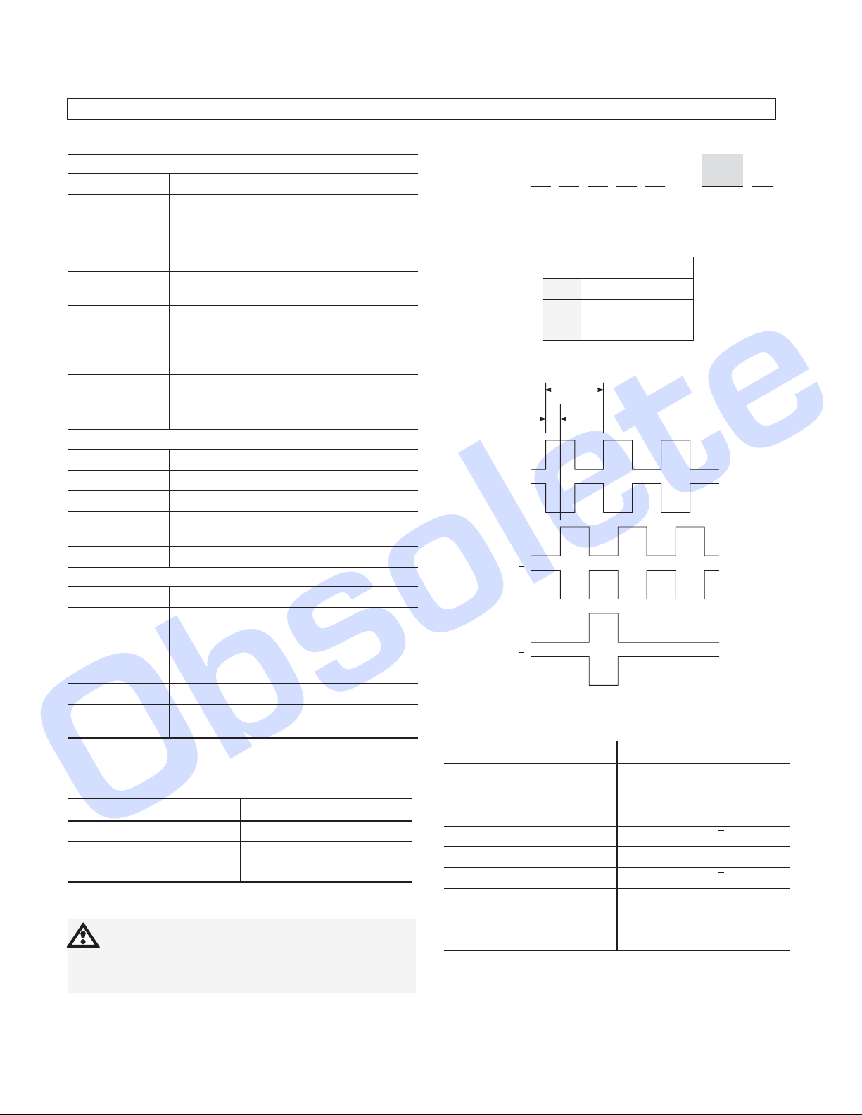
845P — S H C 1 4 — CN 3
a
DIFFER
a
Resolution
Code Description (PPR)
500CM
1000CN
Differential Line Drive Output
1 Cycle
90 +/- 36°
Channel A
Channel A
Channel B
Channel B
Channel Z
Channel Z
(CCW Rotation Shown)
Cable
Differential Line Driver Output
Wire Color
White DC+ Input (5V DC)
Black DC Return
Red Channel A
Violet Channel A
Green Channel B
Blue Channel B
Yellow Channel Z
Orange Channel Z
Shield Floating
Function
Page 2
Obsolete
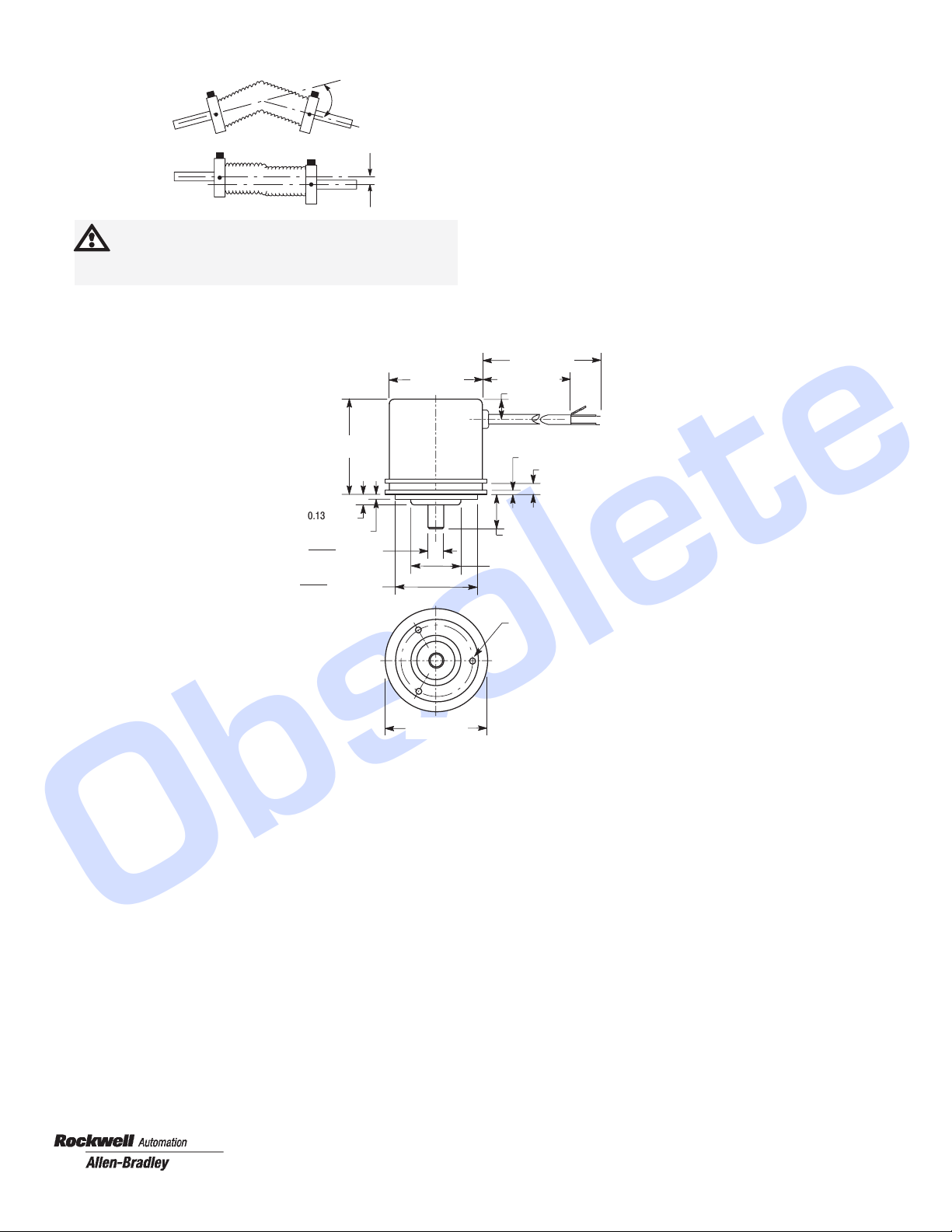
Flexible Shaft Couplings
ATTENTION: Rigidly coupling the encoder shaft
to the machine shaft will cause a failure in either
the bearings of the encoder or the bearings of the
machine shaft.
Dimensions (Approximate)
Dimensions shown in inches (millimeters)
Angle
Parallel
OffĆSet
1.50 (38.1)
Max.
1.59 (40.4)
Dia.
18 (457) Typ.
16 (406) Typ.
0.35
(8.9)
0.062 (1.6)
0.142 (3.6)
0.130 (3.3)
0.055 (1.4)
0.2497
0.2495
1.3750
1.3745
(6.3) Dia.
(34.9) Dia.
1.625 (41.3)
Dia.
Servo Mount
0.622 (15.8)
+ 0.000
- 0.001
(19) Dia.
0.750
4-40 UNCĆ2B x 0.25 (6.4) Deep
on a 1.210 (30.7) Dia. Bolt Circle,
3 PlacesĊ120° Apart
Publication 75008–062–01(B)
May 1999
Printed in USA
 Loading...