

Page 1
Installation Instructions
Size 20 Absolute Encoder, Bulletin 845GM
IMPORTANT: SAVE THESE INSTRUCTIONS FOR FUTURE USE.
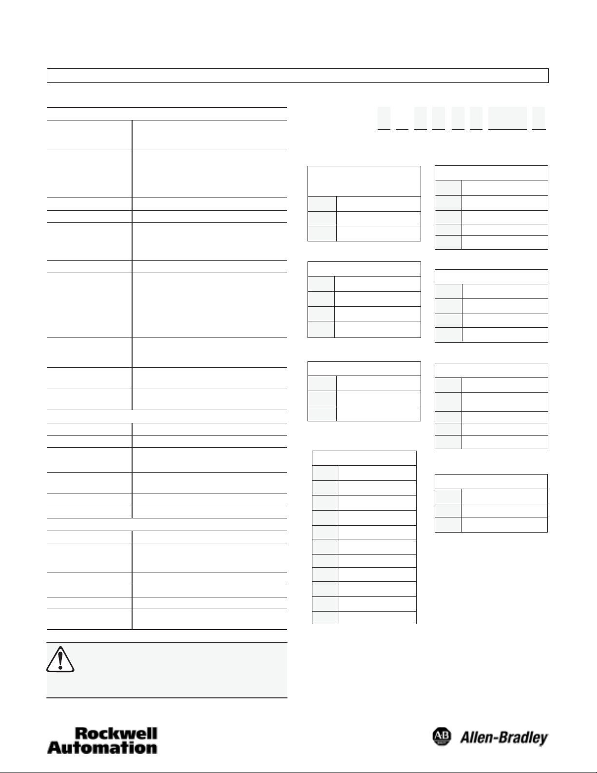
Specifications
Electrical
Code Format Parallel: Gray Code, Natural Binary, Binary Coded
Resolution
Counts per Rev. (CPR)
Accuracy
Requency Response 16K words/sec
Power Requirements Determined by Catalog Number:
Output Drive Capability 16mA
Output Logic Parallel: Gray, Natural Binary or Binary Coded
Latch Command Standard with Natural Binary and BCD
Direction Control Field selectable for increasing counts
Mechanical
Starting Torque
Running Torque
Shaft Loading Axial 40lbs [178N]
Shaft Size 6mm, 10mm, 3/8in (9.517mm), 3/8in (9.517mm)
Moment of Inertia 0.30oz-in2 (54gcm2) maximum
Slew Sped 5000RPM
Environmental
Housing NEMA Type 4, 13; IP65
Temperature 0°C to +85°C (+32°F to +185°F)ĊOperating
Humidity 90%, Noncondensing
Shock 50g (11ms duration)
Vibration 20g (58-150Hz), 1.5mm displacement (10-58Hz)
Appoximate
Shipping Weight
ATTENTION: The shielded cables, output devices,
and power supplies must be properly grounded. All
National Electric Code and applicable local codes
and ordinances must be observed when wiring the
system.
Decimal
SSI: Gray Code
256 CPR (8 bit)
360 CPR (9 or 10 bit)
512 CPR (9 bit)
1000 CPR (12 bit BCD)
1024 CPR (10 bit)
"1 bit
5V DC ±5% @ 150mA maximum
8-24V DC @ 150mA maximum
10-30V DC @ 150mA maximum
Decimal (BCD)
Logic 0" = 0.0 to 0.6V DC
Logic 1" = 3.5 to 5V DC (TTL)
Logic 1" = 24V DC maximum (Open Collector)
Logic 1" = 0.7 x Vs (PushĆPull)
SSI RS-422 compatible
Logic 0" = outputs active (DC common)
Logic 1" = outputs latched (+DC or open)
(CW or CCW)
Reset Reset position value to zero (see Note for reset
pin). Only with shaft stationary.
3.5in-oz. Typical [0.025 NDm]
3.5in-oz. Typical [0.025 NDm]
Radial 40lbs [178N]
w/flat
-20°C to +85°C (-4°F to +185°F)ĊMax Working
-40°C to +100°C (-40°F to +212°F)ĊStorage
1lb (0.45kg)
2048 CPR (11 bit)
4096 CPR (12 bit)
8192 CPR (13 bit)
16384 CPR (14 bit)
32768 CPR (15 bit)
Selection
845GM — F3G 8 H C 1024 R
a b c d e f g h
a
Mounting
Configuration
Code Description
Square FlangeF
S English Servo
Code Description
2 10mm
3 3/8in w/flat
4 3/8in
c
Output Code Type Ê
Code Description
Natural BinaryB
D Binary Coded Decimal
G Gray Code
Code
5
8 8-24V DC
A
e
Output Logic
Code Description
High TrueH
L
Low True Ë
g
Resolution
Code Description/Range
8 bit/0-2550256
0360
4096
Ê PushĆPull or SSI output can only be ordered with 10-30V DC power supply.
Ë Not available with pushĆpull and SSI output. Output logic inverted.
Ì SSI available with Gray Code output only.
Í SSI only available with 12Ćpin connector.
Î Excess 76 used for 9 bit 360 gray code. BCD is 10 bit.
9 or 10 bit/0-359 Î
9 bit/0-5110512
12 bit/0-999 BCD only1000
10 bit/0-10231024
11 bit/0-20472048
12 bit/0-4095
13 bit/0-81918192
14 bit/0-16,383016K
15 bit/0-32,767032K
Output Configuration
Code Description
C
P
S
T 5V DC TTL NPN
Connector Options
Code Description
R
U
b
Shaft Options
6mm1
d
Power Supply
Description
5V DC "5%
10-30V DC Ê
f
NPN Open Collector
24V DC Max.
PushĆPull (7272) Ê
SSI Output ÊÌÍ
h
Radial 19ĆPin
Radial 12ĆPin Í
Page 2
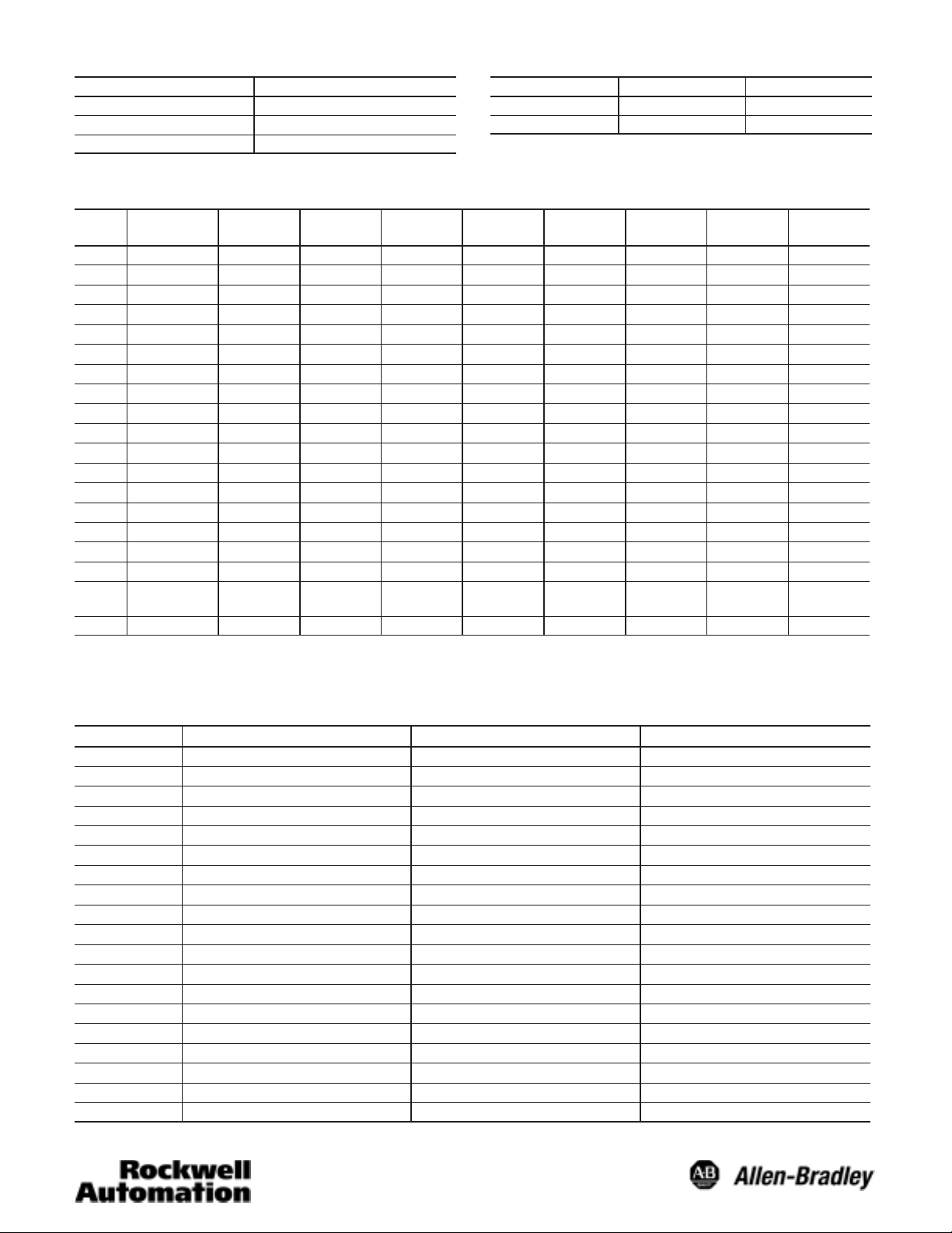
Accessories
Description Part Number
High Performance Flexible Coupling 845-FC-*-*
Measuring Wheels 845-MW-A-*
Servo Clamps 845-SC
*See Sensors catalog for selection.
Number of Pins Mating Connector PreĆWired Cable
12 845-12P 845-CA-G-**
19 845-SCD 845-CA-D-**
Electrical Connections—19 Pin Connector (Gray code or natural binary)
845-CA-D-__
Pin
A Brown G(0) or 2
B Orange G(1) or 2
C Yellow G(2) or 2
D Green G(3) or 2
E Blue G(4) or 2
F Violet G(5) or 2
G Gray G(6) or 2
H White G(7) or 2
J White/Orange G(8) or 2
K White/Brown G(9) or 2
L White/Red G(10) or 2
M White/Yellow G(11) or 2
N White/Green G(12) or 2
P White/Blue G(13) or 2
R White/Black G(14) or 2
S White/Violet
T Black DC Common DC Common DC Common DC Common DC Common DC Common DC Common DC Common
U White/Gray
V Red +DC +DC +DC +DC +DC +DC +DC +DC
Ê Latch control not available with Gray Code or SSI output. On Gray Code encoders this pin is not connected (N/C).
Ë Important—The Direction pin function provides Direction Control for Binary Coded Decimal and Natural Binary or MSBC for parallel Gray Code. See next page for
further detail.
Wire Color
32768
(15 Bit)
0
1
2
3
4
5
6
7
8
9
10
11
12
13
14
Direction Ë Direction Ë Direction Ë
16384
(14 Bit)
G(0) or 2
G(1) or 2
G(2) or 2
G(3) or 2
G(4) or 2
G(5) or 2
G(6) or 2
G(7) or 2
G(8) or 2
G(9) or 2
G(10) or 2
G(11) or 2
G(12) or 2
G(13) or 2
0
1
2
3
4
5
6
7
8
9
10
11
12
13
8192
(13 Bit)
G(0) or 2
G(1) or 2
G(2) or 2
G(3) or 2
G(4) or 2
G(5) or 2
G(6) or 2
G(7) or 2
G(8) or 2
G(9) or 2
G(10) or 2
G(11) or 2
G(12) or 2
N/C
4096
(12 Bit)
0
1
2
3
4
5
6
7
8
9
10
11
12
N/C N/C G(0) or 2
0
G(0) or 2
1
G(1) or 2
2
G(2) or 2
3
G(3) or 2
4
G(4) or 2
5
G(5) or 2
6
G(6) or 2
7
G(7) or 2
8
G(8) or 2
9
G(9) or 2
10
G(10) or 2
11
G(11) or 2
Direction Ë Direction Ë
2048
(11 Bit)
N/C G(1) or 2
0
G(0) or 2
1
G(1) or 2
2
G(2) or 2
3
G(3) or 2
4
G(4) or 2
5
G(5) or 2
6
G(6) or 2
7
G(7) or 2
8
G(8) or 2
9
G(9) or 2
10
G(10) or 2
1024
(10 Bit)
G(2) or 2
G(3) or 2
G(4) or 2
G(5) or 2
G(6) or 2
G(7) or 2
G(8) or 2
G(9) or 2
0
1
2
3
4
5
6
7
8
9
360 and
512 (9 Bit)
0
G(0) or 2
1
G(1) or 2
2
G(2) or 2
3
G(3) or 2
4
G(4) or 2
5
G(5) or 2
6
G(6) or 2
7
G(7) or 2
8
G(8) or 2
N/C N/C
Direction Ë Direction Ë Direction Ë
N/C N/C N/C
N/C N/C N/C
N/C N/C N/C
Reset Reset Reset Reset Reset Reset Reset
N/C N/C N/C N/C N/C
0256
(8 Bit)
G(0) or 2
G(1) or 2
G(2) or 2
G(3) or 2
G(4) or 2
G(5) or 2
G(6) or 2
G(7) or 2
N/C
Latch ControlÊLatch ControlÊLatch ControlÊLatch ControlÊLatch ControlÊLatch ControlÊLatch ControlÊLatch Control
Ê
0
1
2
3
4
5
6
7
Electrical Connections—19 Pin Connector (Binary Coded Decimal)
Pin 845-CA-D-___ Wire Color 1000 BCD (12 Bit) 360 BCD (10 Bit)
V Red +DC +DC
A Brown 1 1
B Orange 2 2
C Yellow 4 4
D Green 8 8
E Blue 10 10
F Violet 20 20
G Gray 40 40
H White 80 80
J White/Orange 100 100
K White/Brown 200 200
L White/Red 400 N/C
M White/Yellow 800 N/C
N White/Green N/C N/C
P White/Blue N/C N/C
R White/Black Direction Control Direction Control
S White/Violet Reset Reset
T Black DC Common DC Common
U White/Gray Latch Control Latch Control
2
Page 3

Electrical Connections for SSI Output—12 Pin Connector
845-CA-G
Catalog Number Wire Pair Wire Color Function Pin
Red +DC Input 8
Black DC Common 1
White Clock + 3
Black Clock - 11
Blue Data + 2
Black Data - 10
Green Direction Control 12
Black Reset 9
845-CA-G-
(With 12 pin connector
-__
Red/Black/Shield
White/Black/Shield
Blue/Black/Shield
Green/Black/Shield
Direction Pin
The Direction Pin can change function with code type. In
parallel type Gray Code encoders, its function is Most
significant Bit Complement or MSBC for short. In Natural
Binary, Binary Coded Decimal and Gray Code SSI encoders,
its function is Direction Control.
Direction Control Ê
Natural Binary and BCD
A logic “1” (+DC or open) on the direction control pin will
produce increasing counts with a counter- clockwise rotation
of the shaft. A logic “0” (DC common) on the direction control
pin will produce increasing counts with a clockwise rotation of
the shaft.
Gray Code (SSI)
A logic “1” (+DC or open) on the direction control pin will
produce increasing counts with a clockwise rotation of the
shaft. A logic “0” (DC common) on the direction control pin will
produce increasing counts with a counterclockwise rotation of
the shaft.
Gray Code (parallel)
Counterclockwise rotation of the shaft will produce increasing
counts. For increasing counts with a clockwise rotation, use
the Most Significant Bit Complement Pin instead of the Most
Significant Bit Pin. See Electrical Connection table for pin
designation.
ATTENTION: For parallel gray code: connecting the
MSB or MSBC to +DC will result in permanent
damage to the encoder.
Reset Pin
The shaft must be stationary before using the reset function.
Connecting the Reset Pin to +DC will reset Natural Binary and
BCD position value to zero. Connecting the Reset Pin to +DC
will reset Gray Code position value to maximum (e.g., 255,
511, 1023, etc.) if MSBC is used, to zero if MSB is used. The
reset function requires a connection to +DC for 0.1 seconds or
longer.
ATTENTION: Activating the Reset Pin results in a
change of position reading. This can cause
unexpected motion which could result in damage to
the product, equipment, or personal injury.
Ê Rotation is viewed from the end of the encoder shaft.
3
Page 4

Dimensions—mm (inches)
(1.84)
3.05 (0.12)
46.7
2.54 (0.10)
46.7
(1.84)
31.72 (1.249)
31.67 (1.247)
6.35 (0.25)
52.3
(2.06)
44.4
(1.75)
52.3
(2.06)
Square Flange Mount
Shaft Options—Square Flange Mount
25.4
(1.0)
19.0
(0.75)
50.8
(2.0)
65.9
(2.59)
max
44.4
(1.75)
3.96 (0.15) dia.
through (4) places
25.4
(1.0)
46.9
(1.85)
31.72 (1.249)
31.67 (1.247)
2.54 (0.10)
52.8
(2.08)
1.27 (0.05)
50.8
(2.0)
English Servo Mount
22.1
(0.87)
50.8
(2.0)
#6-32 UNCĆ2B x
9.52 (0.375) (4)
holes 90_ apart on
a 1.625 dia. B. C.
46.4
(1.82)
21.44
(0.84)
9.52 (0.3749)
9.51 (0.3744)
8.64
(0.34)
22.35
(0.88)
3/8in w/flat 3/8in 6mm 10mm
Shaft Options—English Servo Mount
19.05
(0.75)
9.52 (0.3749)
9.51 (0.3744)
8.64
(0.34)
15.75
(0.62)
3/8in w/flat 3/8in 6mm 10mm
9.52 (0.3749)
9.51 (0.3744)
9.52 (0.3749)
9.51 (0.3744)
22.35
(0.88)
18.87
(0.74)
15.75
(0.62)
Visit our web site at:
http://www.ab.com/sensors
5.99 (0.2358)
5.98 (0.2354)
5.99 (0.2358)
5.98 (0.2354)
4
15.74
(0.62)
12.7
(0.50)
19.0
(0.75)
9.99 (0.3932)
9.97 (0.3926)
9.99 (0.3932)
9.97 (0.3926)
15.08
(0.59)
11.94
(0.47)
18.28
(0.72)
Publication 75008–179–01(C)
May 2004
Printed in USA
 Loading...