

Page 1

Installation Instructions
Size 25 Incremental Encoder, Bulletin 845F
IMPORTANT: SAVE THESE INSTRUCTIONS FOR FUTURE USE.
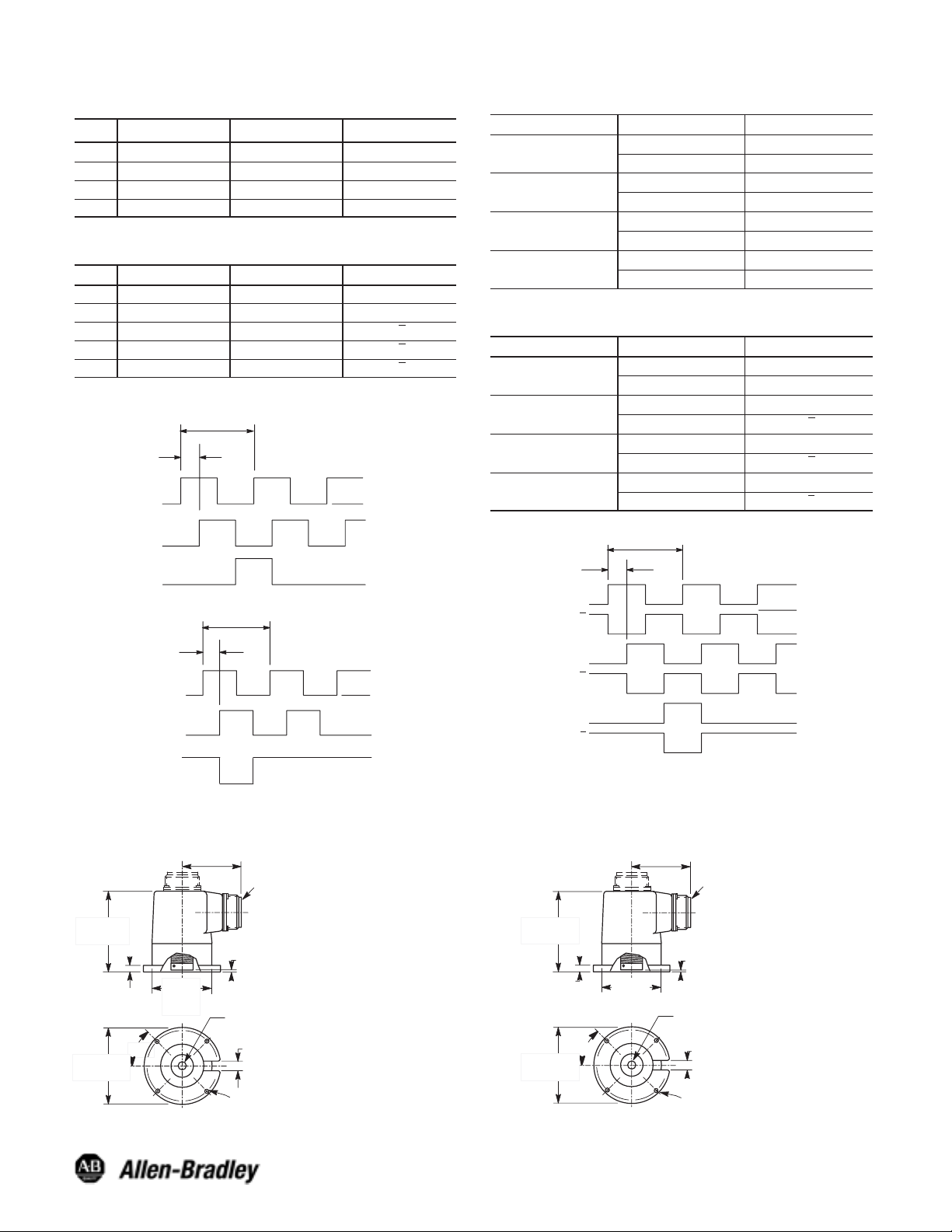
Specifications
Electrical
Code Format Incremental, 2 channels with zero index
Quadrature 90° ±22°
Symmetry 50% ±10%
Zero Index Channel Gated 1/2 cycle
Requirements
Frequency
Response
Operating Speed
Resolution Up to 5000 PPR on code disk
Output Drive
Capability
Channel A leads B CCW
Power
Determined by catalog number:
5V DC ±5% @ 150mA maximum
8-24V DC @ 150mA maximum
Data: 210 kHz
Zero Index: 210 kHz
(210 kHz x 60)/Pulses per revolution = RPM or
(Data)
6000 RPM, whichever is lower
PNP current source = 20mA
NPN current sink = 20mA
Differential line driver = ±20mA
NPN open collector = 20mA
Mechanical
Starting and
Running Torque
Moment of Inertia 27gcm2 (3.9 x 10⁻⁴ozĆinĆsec2)
Slew Speed 6000 RPM
Angular Shaft
Misalignment
Parallel Shaft
Misalignment
Coupling Axial
Compliance
Coupling Bore Size 9.517mm (3/8in) or 6.4mm (1/4in) dia.
2.5Ncm typical (3.5inĆoz)
5° standard coupler, 10° high performance coupler
0.010in standard coupler, 0.020in high performance
coupler
±0.030in standard coupler, ±0.060in high performance
coupler
Environmental
Housing NEMA Type 4, IP66 (IEC 529)
Temperature 0°C to +60°C (+32°F to +140°F) Ċ operating
Humidity 98%, noncondensing
Vibration 20g (5 to 2000Hz)
Approximate
Shipping Weight
-25°C to +90°C (-13°F to +194°F) Ċ storage
Shock 50g (11ms duration)
0.91kg (2lbs)
Accessories
Description Part Number
PreĆWired Cables 845-CA-*-*
Mating Connectors 845-7P, 845-10P
Differential Encoder Buffer Board 845-BB
Selection
845F — S J GZ1 4 FW Y 2 C
a b c d e f
a
Coupling Version
Code Description
Standard 1/4in BoreB
E Standard 3/8in Bore
HighĆPerformance 1/4in BoreF
G HighĆPerformance 3/8in Bore
b
Power Supply
Code Description
5V DC ±5%1
2 8-24V DC Unregulated
c
Output Configuration Ê
Code Description
PNP Current Source2
3 NPN Current Sink
DLD 5V DC RS-4224
5
Ê DLD = Differential Line Driver
NPN Open Collector
24V DC Max
DLD 8-24V DC6
e
Connection Options
Code Description
Axial Connector (End)1
2 Radial Connector (Side)
Axial Cable (End)A
R Radial Cable (Side)
f
Connector/Cable
Options
Code Description
Without Mating ConnectorBlank
C With Mating Connector
1m (3.28ft) Cable Length1
5
5m (16.4ft) Cable Length
9m (29.52ft) Cable Length
9
Code Description (PPR)
CB 60
DB 120
DF 150
CC 254
CK 360
DW 512
DG 720
DL 800
CD 1250
RF 1280
DN
HL 2400
LJ 2750
CT 3600
d
Resolution
1AG
5AM
10BG
50CA
64CE
80CF
100CG
180EB
200CH
250CJ
256CW
300EG
400CL
500CM
600EH
900LG
1000CN
1024FW
1200EL
1472CU
1500EM
1600FL
1800CP
2000
2048CS
2500CR
2540CY
3000EN
5000DR
ATTENTION: The shielded cables, output devices,
and power supplies must be properly grounded. All
National Electric Code and applicable local codes and
ordinances must be observed when wiring the system.
Page 2
7-Pin Connector (ACS02E16S–1P (023) or equivalent)
Current Source, Current Sink, Open Collector Outputs
Pin
A Channel A Output
B Channel B Output F DC Return
C Channel Z Output G Case Ground
DÊ
Function Pin Function
EÊ
DC+ Input Ċ Ċ
Ċ
10-Pin Connector (ACS02E18–1P (023) or equivalent)
Differential LineĆDriver Outputs
Pin
A Channel A Output F DC Return
B Channel B Output G Case Ground
C Channel Z Output H Channel A Output
DÊ
EÊ
Ê Pins D and E internally connected
Function Pin Function
DC+ Input I Channel B Output
Ċ J Channel Z Output
Current Sink and Open Collector Output Waveform:
1 Cycle
90 +/- 22°
Logic 1
Channel A
Channel B
(Index) Channel Z
Logic 0
(CCW Rotation Shown)
Current Source Output Waveform:
1 Cycle
90 +/- 22°
Logic 1
Channel A
Channel B
(Index) Channel Z
Logic 0
(CCW Rotation Shown)
Cable
Current Source, Current Sink, Open Collector Outputs
Wire Pair
Red/Black
White/Black
Blue/Black
Green/Black
Wire Color Function
Red DC+ Input
Black DC Return
White Channel A Output
Black Not Connected
Blue Channel B Output
Black Not Connected
Green Channel Z Output
Black Not Connected
Cable
Differential Line Driver Outputs
Wire Pair
Red/Black
White/Black
Blue/Black
Green/Black
Wire Color Function
Red DC+ Input
Black DC Return
White Channel A Output
Black Channel A Output
Blue Channel B Output
Black Channel B Output
Green Channel Z Output
Black Channel Z Output
Differential Line Driver Output Waveform:
1 Cycle
90 +/- 22°
Channel A
Channel A
Channel B
Channel B
(Index)Channel Z
Channel Z
Logic 1
Logic 0
(CCW Rotation Shown)
Dimensions—mm (inches)
73.91 (2.91) - ACSĆ02E18-1P
63 (2.48) - ACS02E16S-1P
Axial Mount
Connector
104 (4.08)
Max.
5.59 (0.22)
82.6 (3.25)
Dia.
(2.56)
Dia.
o
45
High Performance Coupling Standard Coupling
65
Radial Mount Connector
0.5 (0.02)
9.525 (0.375)
6.35 (0.25)
C
12.7 (0.50)
L
4.59 (0.181) Dia. Hole on a 74.9 (2.952) Dia.
Bolt Circle, 4 PlacesĊ90° Apart
ACS02E18Ć1P (Diff. Line Driver)
or ACS02E16SĆ1P (Current Sink/
Current Source/Open Collector)
+ 0.0005
- 0.0000
+ 0.0005
- 0.0000
Maximum Bore Depth 15.2 (0.60)
Dia.
or
Dia.
73.91 (2.91) - ACSĆ02E18-1P
63 (2.48) - ACS02E16S-1P
Axial Mount
Connector
91.9 (3.62)
Max.
5.59 (0.22)
82.6 (3.25)
45
Dia.
ACS02E18Ć1P (Diff. Line Driver)
or ACS02E16SĆ1P (Current Sink/
Current Source/Open Collector)
Radial Mount Connector
0.5 (0.02)
65
(2.56)
Dia.
o
9.525 (0.375)
6.350 (0.25)
C
L
4.59 (0.181) Dia. Hole on a 74.9 (2.952) Dia.
Bolt Circle, 4 PlacesĊ90° Apart
+ 0.0005
Dia.
- 0.0000
or
+ 0.0005
Dia.
- 0.0000
Maximum Bore Depth 12.7 (0.50)
12.7 (0.50)
Publication 75008–189–01(B)
February 2004
Printed in USA
 Loading...