

Page 1
Installation Instructions
Size 25 Absolute Encoder, Bulletin 845D
IMPORTANT: SAVE THESE INSTRUCTIONS FOR FUTURE USE.
Specifications
Electrical
Code Format Binary Coded Decimal (BCD)
Resolution (Gray and Natural Binary):
Accuracy ±1 bit
Frequency Response 16K words/sec
Power Requirements Determined by catalog number:
Output Drive Capability NPN current sink = 16mA
Output Logic Parallel BCD, GRAY, or NAT BIN:
Latch Command Optional with BCD and NAT BIN only:
Direction Control Field selectable for increasing counts (CW or CCW)
Gray Code
Natural Binary
256 CPR (8 bit); 512 CPR (9 bit)
1024 CPR (10 bit)
(BCD):
360 CPR (10 bit); 1000CPR (12 bit)
5V DC ±5% @ 400mA maximum
8-24V DC @ 400mA maximum
Logic 0" = 0.0 to 0.6V DC
Logic 1" = 3.5 to 5.0V DC (TTL)
Logic 1" = 24V DC maximum
(Open collector)
Logic 0" = outputs active
(DC common)
Logic 1" = outputs latched
(+DC or open)
Reset Reset position value to zero (see Reset Pin section on
page 2). Only with shaft stationary.
Mechanical
Starting and Running
Torque
Shaft Loading Axial 89N [20lbs]; Radial 178N [40lbs]
Shaft Size 6mm, 10mm, 1/4in, 3/8in diameter
Moment of Inertia 54g-cm2 (0.3ozĆin2)
Slew Speed 5000 RPM
2.5 Ncm typical [3.5inĆoz]
Environmental
Housing NEMA Type 4, IP66 (IEC 529); NEMA Type 4X on
Temperature 0°C to +85°C (+32°F to +185°F )Ċoperating
Humidity 98%, noncondensing
Vibration 20g (58 to 150Hz)
Approximate Ship
Weight
selected models
-25°C to +90°C (-13°F to +194°F)Ċstorage
Shock 50g (11ms duration)
0.91kg (2lbs)
Accessories
Description Catalog Number
High Performance Flexible Coupling 845-FC-*-*
Measuring Wheels 845-MW-A-*
Servo Clamps 845-SC
PreĆWired Cables 845-CA-D-*
Mating Connectors 845-SCD
Selection
845D — S J D Z 1 4 B D CK 4
a b c d e f g h i
a
NEMA Rating
Code Description
NEMA 4J
X NEMA 4X
b
Mounting Configuration
Code Description
Square FlangeD
E 70mm Diameter Flange
90mm Diameter FlangeF
G Metric Servo 48mm B.C.
English ServoH
J Metric Servo 42mm B.C.
c
Shaft Options
Code Description
6mm DiameterA
B 10mm Diameter
1/4in DiameterC
Z 3/8in Diameter
6mm w/FlatK
L 10mm w/Flat
M 1/4in w/Flat
3/8in w/FlatN
d
Power Supply Options
Code Description
5V DC ±5%1
2 8-24V DC Unregulated
e
Output Configuration
Code Description
5V DC TTL Compatible4
5
NPN Open Collector
24V DC Max.
ATTENTION: The shielded cables, output devices,
and power supplies must be properly grounded. All
National Electric Code and applicable local codes
and ordinances must be observed when wiring the
system.
Latch Options
Code Description
B
Output Code Type
Code Description
G Gray Code
Code Description
CW
DW
FW
CK
CN
Connector Options
Code Description
1
2
4
5
f
No LatchA
Latch (Sink Output
Module Compatible)
g
Binary Coded DecimalD
Natural BinaryN
h
Resolution
256
512
1024
360
1000
Gray Code
Natural Binary
Binary Coded
Decimal
i
Axial Connector
(End) without Mate
Radial Connector
(Side) without Mate
Axial Connector
(End) with Mate
Radial Connector
(Side) with Mate
or
1
Page 2
Electrical Connections
Function
Pin Gray Code Natural Binary BCD (8421)
A G(0) 2
B G(1) 2
C G(2) 2
D G(3) 2
E G(4) 2
F G(5) 2
G G(6) 2
H G(7) 2
J G(8) 2
K G(9) 2
L MSB Complement Not Used 400
M Not Used Not Used 800
N Not Used Not Used Not Used
P Not Used Not Used Not Used
R Not Used Direction Control Direction Control
S Reset Reset Reset
T DC Return DC Return DC Return
U Not Used Latch Control Latch Control
V DC+ Input DC+ Input DC+ Input
0
1
2
3
4
5
6
7
8
9
1
2
4
8
10
20
40
80
100
200
Direction Pin
The Direction Pin can change function with code type. In
parallel type Gray Code encoders, its function is Most
significant Bit Complement or MSBC for short. In Natural
Binary and Binary Coded Decimal encoders, its function is
Direction Control.
Direction Control Ê
Natural Binary and BCD
A logic “1” (+DC or open) on the direction control pin will
produce increasing counts with a counter- clockwise rotation
of the shaft. A logic “0” (DC common) on the direction control
pin will produce increasing counts with a clockwise rotation of
the shaft.
Gray Code (parallel only)
Counterclockwise rotation of the shaft will produce increasing
counts. For increasing counts with a clockwise rotation, use
the Most Significant Bit Complement Pin instead of the Most
Significant Bit Pin. See Electrical Connection table for pin
designation.
ATTENTION: For parallel gray code: connecting the
MSB or MSBC to +DC will result in permanent
damage to the encoder.
Reset Pin
The shaft must be stationary before using the reset function.
Connecting the Reset Pin to +DC will reset Natural Binary and
BCD position value to zero. Connecting the Reset Pin to +DC
will reset Gray Code position value to maximum (e.g., 255,
511, 1023, etc.) if MSBC is used, to zero if MSB is used. The
reset function requires a connection to +DC for 0.1 seconds or
longer.
ATTENTION: Activating the Reset Pin results in a
change of position reading. This can cause
unexpected motion which could result in damage to
the product, equipment, or personal injury.
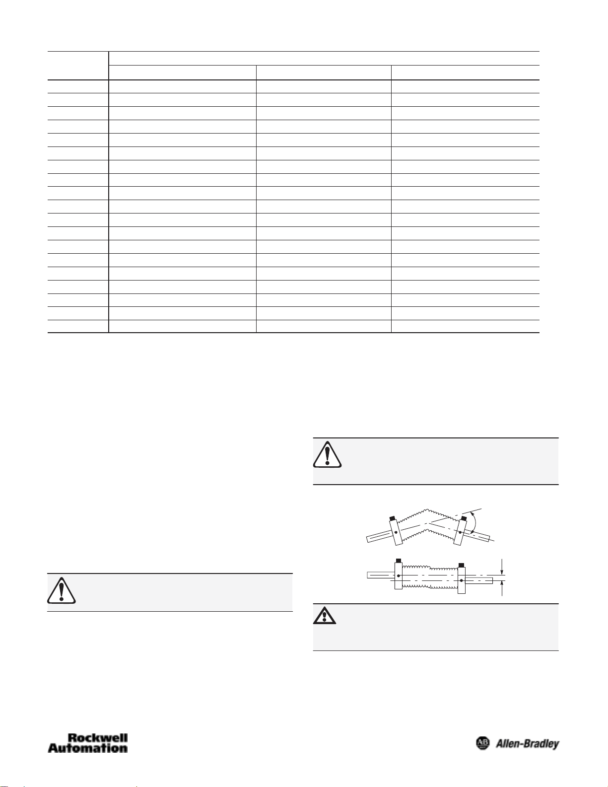
Flexible Shaft Couplings
Angle
Parallel
OffĆSet
ATTENTION: Rigidly coupling the encoder shaft to
the machine shaft will cause a failure in either the
bearings of the encoder or the bearings of the
machine shaft.
Ê Rotation is viewed from the end of the encoder shaft.
2
Page 3

Dimensions—mm (inches)
Axial Mount
Connector
58.42
(2.30)
Connector
PT02E14-19P (023)
Axial Mount
Connector
58.42 (2.30)
Connector
PT02E14-19P (023)
Axial
Mount
Connector
79.7
(3.13)
3.05
(0.12)
20.0
(0.79)
See
Table
Below
74.93
(2.95)
7.62 (0.30)
See Table Below
26.21(1.032)
26.21
(1.032)
52.40
(2.063)
58.42
(2.30)
6.35
(0.25)
(1.25) Dia.
52.40
(2.063)
66.5
(2.62) Sq.
Square Flange Mount
Connector
PT02E14-19P (023)
Axial Mount
Connector
79.7
(3.13)
Radial
Mount
Connector
20.0
(0.79
)
See Table Below
31.75
M4 x 5.0 Deep
on a 70.0 Dia.
Bolt Circle,
4 PlacesĊ90°
Apart
3.05
(0.12)
Radial Mount
Connector
6.35 (0.25)
22.86/21.59
(0.90/0.85)
31.75
(1.25) Dia.
5 (0.21) Dia.Ċ4 Mtg. Holes
10-32 UNFĆ2B X 9.6 (0.38) Deep
on a 47.6 (1.875) Dia. Bolt Circle,
3 PlacesĊ120° Apart
58.42
(2.30)
Connector
6.35
(0.25)
31.75
(1.25) Dia.
Radial
Mount
Axial Mount
Connector
74.93
(2.95)
7.62
(0.30)
See Table
Below
58.67
(2.31)
Dia.
74.93
(2.95)
7.62 (0.30)
See Table Below
58.67
(2.31) Dia.
58.42
(2.30)
31.75
(1.25) Dia.
63.5
(2.5)
Dia.
63.50
(2.50) Dia.
65.0
(2.56) Dia.
English Servo Mount
Connector
PT02E14-19P (023)
Axial Mount
Connector
Radial
Mount
Connector
2.54
(0.10)
20.0
(0.79)
M3 x 5.0 Deep on a
48.0 Dia. Bolt Circle
3 PlacesĊ120° Apart
74.93
(2.95)
7.62
(0.30)
See Table
Below
58.67
(2.31)
Dia.
Radial Mount
Connector
2.54
(0.10)
2.54
(0.10)
22.86/21.59(0.90/0.85)
31.75
(1.25) Dia.
10-32 UNFĆ2B x 9.6 (0.38) Deep
on a 47.6 (1.875) Dia. Bolt Circle,
3 PlacesĊ120° Apart
58.42
(2.30)
20.0
(0.79)
31.75
(1.25) Dia.
63.5
(2.5)
Dia.
Radial
Mount
Connector
2.54
(0.10)
M4 x 5.0 Deep on a
70.0
(2.76) Dia.
64.0 Dia. Bolt
Circle, 4 PlacesĊ
90° Apart
Metric Flange Mount
Shaft Diameter Options
Code Shaft Diameter
A or K 6mm +0.00mm, -0.013mm
B or L 10mm +0.00mm, -0.013mm
C or M 6.35(0.2499 ) +0.0000, -0.0005
Z or N 9.52 (0.3749) +0.0000, -0.0005
90.0
(3.54) Dia.
Shaft with Flat Option
19.05
(0.75)
M4 x 5.0 Deep on a
42.0 Dia. Bolt Circle
65.0
(2.56) Dia.
3 PlacesĊ120° Apart
Metric Servo Mount
Flat Dimensions
Code Dimension A"
A
K 5.3mm (0.21in)
L 9.1mm (0.36in)
M 5.5mm (0.22in)
N 8.6mm (0.34in)
3
65.0
(2.56) Dia.
Page 4

4
Publication 75008–184–01(B)
January 2005
Printed in USA
 Loading...