

Page 1
Installation Instructions
Teth
A
7.25 dia. B.C. (to fit 8
Teth
3/8I bolt
(
Tether, 3/8 bolt on a
5V DC in, 5V DC
5-26V DC in, 5-26V
5-15V DC in, 5-15V
,
8-26V DC in
10-30V DC in, 10-30V
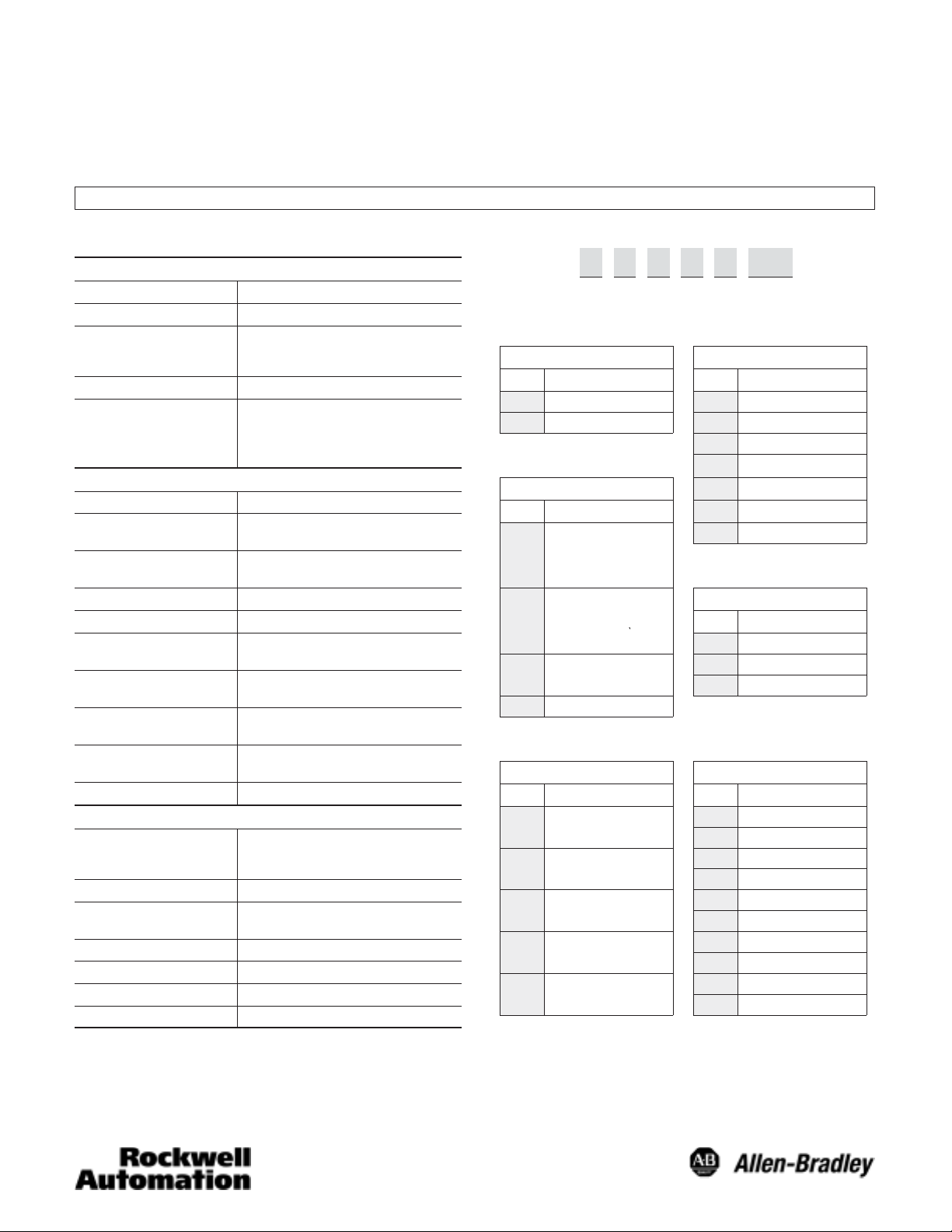
Bulletin 844D Blind & ThroughĆShaft Optical Incremental Encoders
IMPORTANT: SAVE THESE INSTRUCTIONS FOR FUTURE USE.
Specifications
Electrical
Code Format 2 channels with zero index
Power Requirements 120mA (no load)
Max Output Frequency 200kHz PushĆPull (120-8192 PPR)
Resolution Up to 16,384 pulses per revolution
Output Driver Capability
Mechanical
Angular Acceleration 100,000 radians/sec
Starting Torque
@ 25_C (77_F)
Running Torque
@ 25_C (77_F)
Moment of Inertia 490gcm2 (6.9 x x 10-3oz-in-sec2)
Slew Speed 3000 rpm maximum
Shaft Loading
(120-2500 PPR)
Shaft Loading
(4096-16,384 PPR)
Permissible Shaft
Radial Movement
Permissible Shaft
Axial Movement
Bore Size Supports 1/2 to 1-1/8" & 30mm shafts
Environmental
Protection NEMA Type 4, 13, IP66 (IEC 529) except
Housing Material Aluminum
Temperature
Humidity 90% noncondensing
Vibration 20g from 5 to 2000Hz
Approximate Weight 0.91kg (2lbs)
300kHz all other drivers (120-8192 PPR)
600kHz (above 8192 PPR)
3487 Line driver = "40 mA
4469 Line driver = "200 mA
7272 Line driver = "40 mA
PushĆPull Single Ended Driver = "70 mA
9.3Ncm (13inĆoz)
5Ncm (7 inĆoz)
Axial 67N (15lbs)
Radial 133N (30lbs)
Axial 44N (10lbs)
Radial 67N (15lbs)
Static +/- 0.5mm (0.02in)
Dynamic +/- 0.1mm (0.004in)
Static +/- 0.5mm (0.02in)
Dynamic +/- 0.5mm (0.02in)
terminal block connection type rated
IP40 (IEC 529) only
-20_C to 85_C (-4_F to +185_ F)ĊOperating
-30_C to 85_C (-22_F to +185_F)ĊStorage
Shock 50g for 11ms
Selection
844D — A 5 A C 1 CR
a b c d e f
a
Shaft Design
Code Description Code Description
A BlindĆShaft 4 1/2in
B ThroughĆShaft 5 5/8in
6 3/4in
c
2
Mounting Configuration
7 7/8in
8 1.0in
Code Description 9 1 1/8in
I
er, 1/2I bolt on a
7.25I dia. B.C. (to fit 8
A
1/2I NEMA C face)
I
er,
5.88I dia. B.C. (to fit 4
B
1/2I NEMA C face)
Tether, 3/8I bolt on a
C
2.5-4.0I dia. radius
D AntiĆrotation pin
on a
M 30mm
Code Description
C 10Ćpin Connector
T
1 1m (3.28ft) cable
ef
Power Supply and Output Ì
Code Description Code Description (PPR)
5V DC in, 5V DC
1
2
3
4
5
Ê Shaft sizes below 1.0in include an insulating insert.
Ë Terminal block unit is not rated for fluid ingress protection (IP40 (IEC 529)
only).
Ì DLD = Differential Line Driver
Í 7272 line driver has a voltage drop of 1.9V.
Î Available with power supply and output options 1, 2, 3 and 4.
DLD out (3487)
5-26V DC in, 5-26V
DC DLD out (7272) Í
5-15V DC in, 5-15V
DC DLD out (4469)
8-26V DC in
5V DC DLD out (3487)
10-30V DC in, 10-30V
DC PushĆPull out
,
DB 120
CK 360
FW 1024
CS 2048
CR 2500
DS 4096
DR 5000
FS 8192
CV
LS
b
Shaft Size Ê
d
Connection Type
Terminal Block Ë
Resolution
10000 Î
16384 Î
Page 2
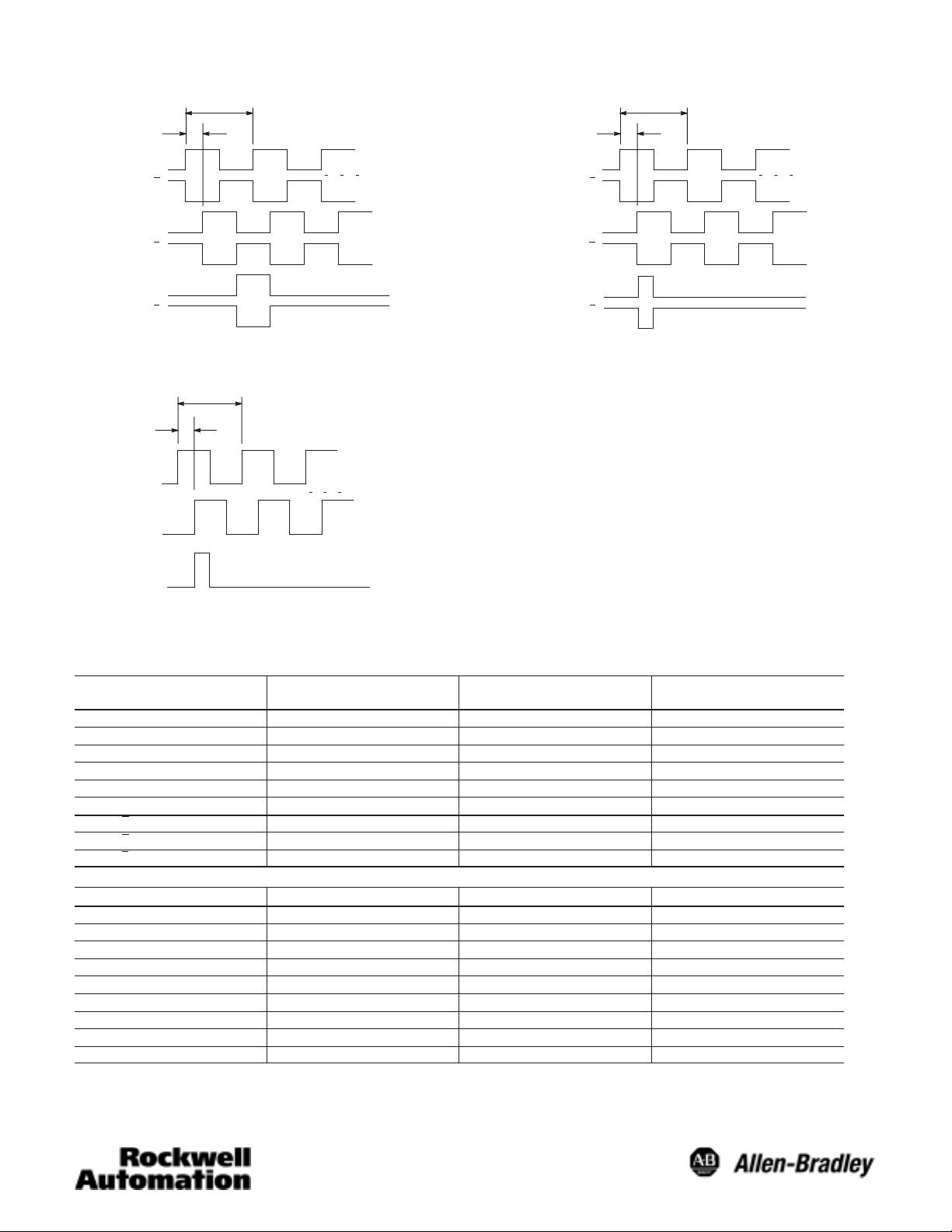
Differential Line Driver Output (for resolution v 8192 PPR)
1 Cycle
90 +/- 22°
Channel A
Channel A
Logic 1
Logic 0
Differential Line Driver Output (for resolution u 8192 PPR)
1 Cycle
90 +/- 22°
Channel A
Channel A
Logic 1
Logic 0
Channel B
Channel B
(Index) Channel Z
Channel Z
(CCW Rotation Shown)
Channel B
Channel B
(Index) Channel Z
Channel Z
PushĆPull Single End Driver Output
1 Cycle
90 +/- 22°
Logic 1
Channel A
Channel B
(Index) Channel Z
Logic 0
(CCW Rotation Shown)
Electrical Connections
Table A: Differential Line Driver Outputs
Function
Channel A Output A White 1
Channel B Output B Pink 2
Channel Z Output C Violet 7
DC+ Input D Red 3
DC Return F Blue 4
Case Ground G Green Ċ
Channel A Output H Brown 5
Channel B Output I Black 6
Channel Z Output J Yellow 8
Connector
Table B: PushĆPull Outputs
10ĆPin
Function
Channel A Output A White 1
Channel B Output B Pink 2
Channel Z Output C Violet 7
DC+ Input D Red 3
DC Return F Blue 4
Case Ground G Green Ċ
Not connected Ċ Brown Ċ
Not connected Ċ Black Ċ
Not connected Ċ Yellow Ċ
Note: 10-pin connector type MS3102R18–1P
10ĆPin Connector Shielded Cable Terminal
Shielded
Cable
Terminal
(CCW Rotation Shown)
2
Page 3

844D
Blind-Shaft Tolerance
SIze
1/2I 0.500/0.501 0.500/0.499 0.70/2.00
5/8I 0.625/0.626 0.625/0.624 0.70/2.00
3/4I 0.750/0.751 0.750/0.749 0.70/2.00
7/8I 0.875/0.876 0.875/0.874 0.70/2.00
1.0I 1.000/1.001 1.000/0.999 0.70/2.00
1 1/8I 1.125/1.126 1.125/1.124 0.70/2.00
30mm 30.000/30.025mm 30.000/29.975mm 18/50mm
844D
Through-Shaft Tolerance
Size
1/2I 0.500/0.501 0.500/0.499 0.70
5/8I 0.625/0.626 0.625/0.624 0.70
3/4I 0.750/0.751 0.750/0.749 0.70
7/8I 0.875/0.876 0.875/0.874 0.70
1.0I 1.000/1.001 1.000/0.999 0.70
1 1/8I 1.125/1.126 1.125/1.124 0.70
30mm 29.980/29.959mm 30.000/29.975mm 18mm
Dimensions—mm (inches)
Blind-Shaft Ê
Bore Mating Shaft Length
Bore Mating Shaft LengthĊmin.
Connector
Option
Cable
Option
Terminal
Option
∅89.66
(3.53)
Through-Shaft Ê
∅89.66
(3.53)
43.18
(1.70)
46.23
(1.82)
19.05 (0.75)
12.7 (0.50)
11.43 (0.45)
∅57.15
∅50.0
(1.97)
Clamp Ring
3.17 (0.125)
12.7 (0.50)
11.43 (0.45)
∅50.0
(1.97)
Clamp Ring
3.17 (0.125)
(2.25)
19.05 (0.75)
∅57.15
(2.25)
7.14
(0.28)
12.7
(0.50)
16.94
(0.673)
87.1
(3.43)
30_
6.35/6.36
(0.25)
AntiĆRotation
Pin
15_
38.1 (1.5)
87.3
(3.44)
22.4
(0.89)
(2.0)
5.59
(0.22)
51
107.5
(4.23)
76.2 (3.0)
65.0 (2.56)
23.11
(0.91)
65.53
(2.58)
#10-32UNC-28
X0.25 DP (3) Plcs
on a 3.000 B.C.
Tether Option “B”Tether Option “A”
7.14
(0.28)
12.7
(0.5)
12.7
(0.5)
5.59
(0.22)
30_
∅1.0008
1.0028
38.1 (1.5)
(3.44)
87.3
Bore
5.59
(0.22)
(1.00)
(2.00)
Tether Option “C”
18.2
87.5
(0.72)
(3.45)
51
(2.0)
76.2 (3.0)
65.0 (2.56)
25.4
50.8
13.21
(0.52)
38.10
(1.50)
∅76.2
(3.0)
12.78/12.73
(0.503/0.501)
25.4
(1.0)
85.3
(3.36)
18.16
(0.71)
65.53
(2.58)
38.1
(1.5)
∅0.218
2 Plcs
101.6
(4.0)
Ê Shown with optional anti-rotation pin.
3
Page 4

Mounting Instructions
IMPORTANT: Be sure mating shaft is chamfered and
grease-free.
1. Loosen the screw on the clamping ring with a 3/32 inch
hexagon socket wrench.
2. Slide the encoder onto the mating shaft until the tether
mount or anti-rotation pin rests on the machine surface.
The encoder should slide freely on the shaft; if not, do not
force. Check the shaft for interferences such as gouges,
burrs, rust or size.
If a mounting hole or anti-rotation pin stop already exists,
proceed to step 6.
3. Mark the mounting hole and/or anti-rotation pin stop
location.
4. Slide the encoder off. Drill and tap the marked hole to
accept the 0.375 inch x 16 (tether option B or C) or 0.5
inch x 13 (tether option A) bolt.
5. Slide the encoder back in the shaft until the tether mount
or anti-rotation pin rests on the machine surface.
6. Attach the encoder with either the 0.375 inch or 0.5 inch
bolt.
IMPORTANT: Do not stress the tether mount while
tightening the bolt.
7. Tighten the clamping ring to 8 inch-lbs.
8. Make the electrical connections according to the table
under “Electrical Connections.”
IMPORTANT: Wiring must be in accordance with the
National Electric Code and applicable local codes and
ordinances.
9. Apply the specified voltage (see Table “e” under
“Selection” on page 1 of this publication).
Visit our web site at:
http://www.ab.com/sensors
4
Publication 75008–147–01(B)
February 2003
Printed in USA
 Loading...