

Page 1
Installation Instructions
Bulletin 844C Hollow ThroughĆShaft Incremental Encoders
IMPORTANT: SAVE THESE INSTRUCTIONS FOR FUTURE USE.
Selection
844C — Z3 05D 02500
a b c
a
Shaft Options
Code Description
06 6mm
08 8mm
10 10mm
12 12mm
Z3
Z4
3/8I
1/2I
b
Power Supply & Output Ê
Code Description
05D
10D
10P
Ê DLD = Differential Line Driver
P–P = Push-Pull Single Ended Driver
4 to 6V DC in,
DLD RS422 Output
10 to 30V DC in,
5V DC DLD RS422 Output
10 to 30V DC in,
10-30V DC PĆP Output
c
Resolution
Code Description
00100 100
00250 250
00360 360
00500 500
01000 1000
01024 1024
01250 1250
02000 2000
02048 2048
02500 2500
03600 3600
04096 4096
05000 5000
07200 7200 Ë
08192 8192 Ë
10000 10000 Ë
Ë Available with 4–6V power supply and
output only.
Specifications
Electrical
Code Format 2 channels with zero index
Quadrature
Symmetry 40% to 60%
Operating Voltage 4ć6V DC, 10ć30V DC w/RS422 Output
Power Requirements 100mA @ 5V DC (no load)
Max Output Frequency 300kHz (RS422)
Resolution Up to 10,000 pulses per revolution
Integral Cable 1.5m (5ft)
Output Drivers RS422 Line driverĊ3487
Mechanical
Angular Acceleration 50,000 radians/sec2 maximum
Moment of Inertia 45gcm
Maximum Operating Speed 6000rpm at max shaft loading
Maximum Torque 0.2Ncm (0.28oz in) Operating
Permissible Shaft Movement Radial 0.05mm (0.002in)
Maximum Shaft Loading Axial 0.45kg (1lb)
Environmental
Housing Aluminum
Temperature
Humidity 90% noncondensing
Protection IP65 (IEC529)
Vibration 20Gs/10-150Hz
Approximate Weight 0.3kg (11oz)
90_ ±22_ channel A leads B CW
10ć30V DC w/PushĆPull Output
120mA @24V DC (no load)
200kHz (PushĆPull)
10-30V DC Line driverĊ7272
2
(0.25ozĆin2) maximum
0.4Ncm (0.57oz in) Starting
Axial ±0.2mm 〈±0.008in)
Radial 1.36kg (3lb)
-20_C to 70_C working
-20_C to 85_C operating
-20_C to 85_C storage
Shock 30Gs/11msec
Page 2
Mounting Instructions
11.0/25.0 (0.433/0.984)
IMPORTANT: Be sure the mating shaft meets the
tolerance requirements shown in the tables in the
Dimensions section.
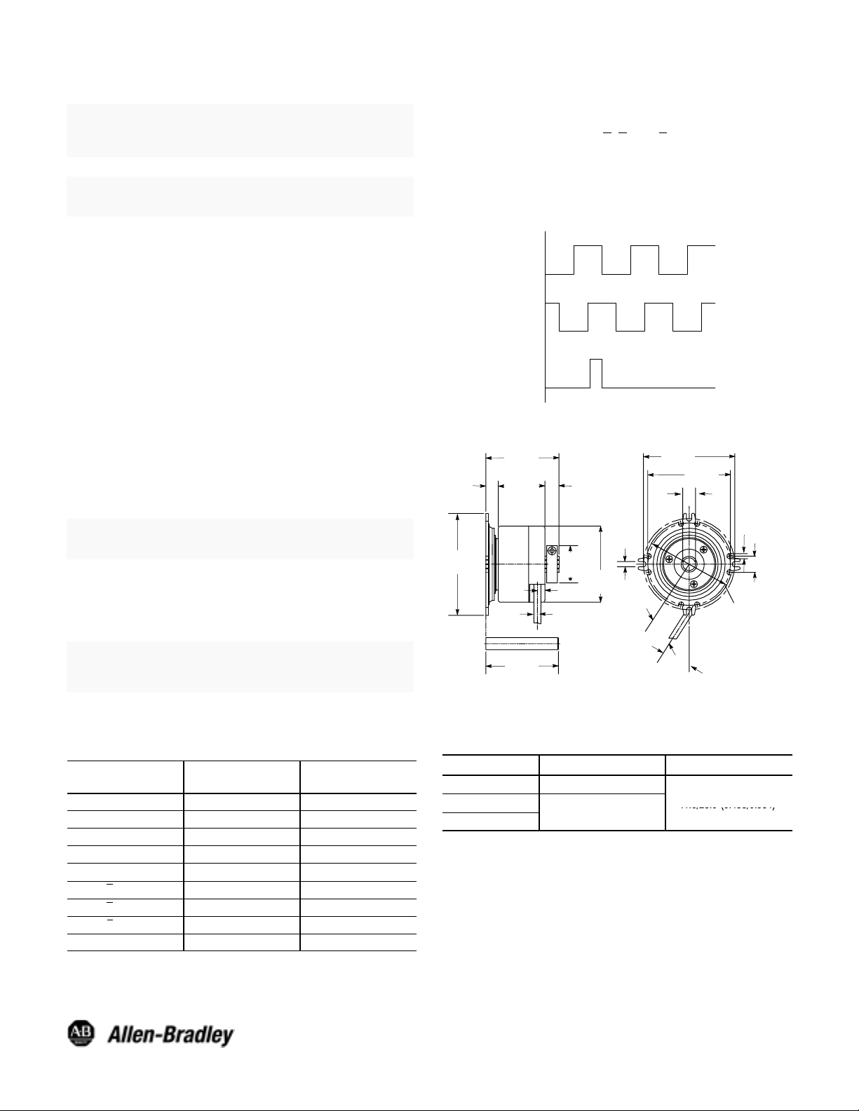
Output Waveforms
1. Channel A leads Channel B for clockwise rotation when
viewed from face of the encoder.
2. Complementary signals (A
units with line drivers.
, B, and Z) are supplied only on
IMPORTANT: Be sure mating shaft is chamfered and
grease-free.
1. Loosen the screw on the clamping ring with the 2.5mm
hexagon socket wrench.
2. Slide the encoder onto the mating shaft until the flex mount
rests on the machine surface.
The encoder should slide freely onto the shaft; if not, do
not force. Check the shaft for interferences such as
gouges, burrs, rust or size.
If mounting holes already exist, proceed to Step 6.
3. Hold encoder firmly and mark the four mounting holes.
4. Slide the encoder off. Drill and tap the marked holes to
accept M4 (or equivalent) screws.
5. Slide the encoder back onto the shaft until the flex mount
rests on the machine surface.
6. Attach the encoder with four M4 (or equivalent) screws.
IMPORTANT: Do not stress the flex mount while
tightening the screws.
7. Tighten the clamping ring screw to 1.1 Nm (10 in–lbs).
8. Make the electrical connections according to the table
under Electrical Connections.
IMPORTANT: Wiring must be in accordance with the
National Electric Code and applicable local codes and
ordinances.
3. Marker Pulse is 1/4 cycle and is gated on the positivegoing edge of Channel B for clockwise rotation.
Channel
A
B
Z
Dimensions—mm
20.4
(9.80)
72
(2.84)
32.5_
DIM
X"
65
(2.56)
68
(2.68)
4.2
(0.17)
(0.47)
12
(0.37)
80.8
(3.18)
57.8
(2.28)
∅29.5
(1.16)
(0.24)
∅5.5
(0.22)
6
11
(0.43)
∅60
(2.36)
3.4
(0.13)
9.8
37
(1.46)
57
(2.24)
min
9. Apply the specified voltage.
Electrical Connections
Function
V DC Red Red
Common Blue Blue
A Output White White
B Output Pink Pink
Z Output Violet Violet
A Output Brown NC
B Output Black NC
Z Output Yellow NC
Shield Drain Wire Drain Wire
Wire Color
Line Driver
Open Collector
Wire Color
844C Mating Shaft Tolerance—mm (inches)
6mm to 10mm +0.0/-0.015 (+0.0/-0.0006)
Visit our web site at:
http://www.ab.com/sensors
Bulletin 844C
Bore Diameter Length
3/8I
1/2I
+0.0/-0.018 (+0.0/-0.0007)
11.0/25.0 (0.433/0.984)
Publication 75008–133–01(B)
Document 910 990 103 489
February 2000
Printed in USA
 Loading...