

Page 1
Installation Instructions
IMPORTANT: SAVE THESE INSTRUCTIONS FOR FUTURE USE.
ATTEN TI ON : Rockwell Automation Bulletin
2090 feedback cables provide connections
for both 5…12V and 7…12V encoder power
supplies. Only one of these connections
should be used. Simultaneous connection
to different power supplies may result in
damage to the servo drive and encoders.
842HR Sine Cosine/Serial Encoders
Size 25, High Resolution Auxiliary Servo Feedback
Description
Bulletin 842HR is a 15-bit serial/sine cosine encoder. Targeted for
high performance digital servo drive systems that require
absolute feedback for position control and high resolution
incremental feedback for speed control.
Rockwell Automation’s sine cosine high performance encoders
provide commutation, speed regulation and position control all
in one device. Absolute position values of up to 15 bit combined
with incremental resolution up to 2 million counts per turn.
Features
• Absolute feedback for position control
• High resolution Incremental feedback for speed control
• Commutation
• Sine cosine differential interface
• Digital bi-directional RS-485 interface
• Compatible with Hiperface® interface
• Internal diagnostic functions
Benefits
• High performance motor or auxiliary feedback
• High accuracy and resolution
•Low bandwidth
• Maximum noise immunity
• One interface for all servo motor applications
• Standalone housing (suitable for mounting external to a servo
motor
Hiperface is a registered trademark of SICK Stegmann Gmb H
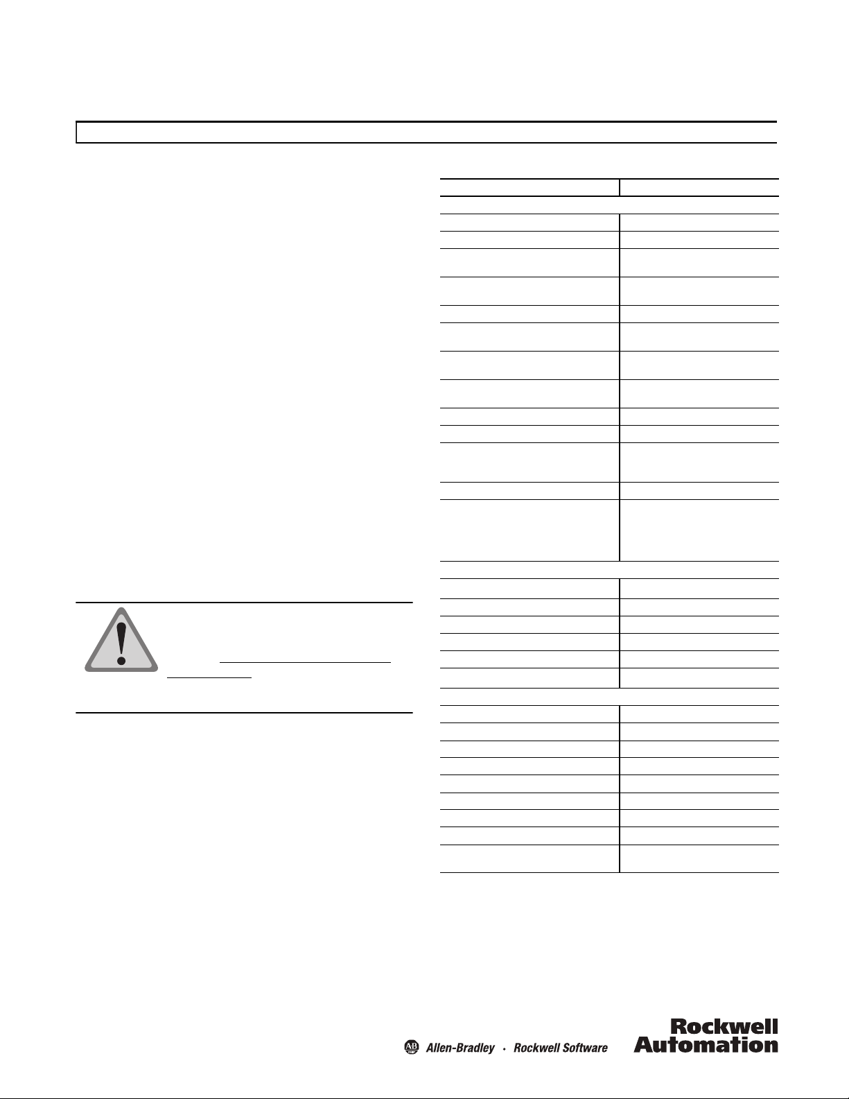
Specifications
Certifications CE Marked for all applicable directives
Electrical
# of sine/cosine cycles per revolution 1,024
Code format for absolute position value Binary
Code direction with clockwise rotation viewed
from shaft end
# of steps per revolution
(Single 842HR-S)
# of revolutions (Multi 842HR-M) 4,096
Error limits for the digital absolute value via RS
485
Error limits in evaluating the 1,024 signals,
integral non-linearity
Non-linearity within a sine/cosine period,
differential non-linearity
Output frequency for sine/cosine signals 0…200 kHz
Operating voltage range 7…12V; 5…12V
Max. operating current, no load
5…12V Supply
7…12V Supply
Available memory on EEPROM 128 bytes
Interface signals
Process data channel = SIN,
REFSIN, COS, REFCOS
Parameter channel = RS 485
Mechanical
Max. angular acceleration
Max. operating speed 6,000 RPM
Operating torque, max. 3.5 oz-in
Starting to rque, max. 5 oz-in
Shaft loading Radial 35 lb; Axial 40 lb
Life of ball bearings
Environmental
Housing Aluminum
Operating Temperature—C (F) -20…+85° (-4…185°)
Storage Temperature—C (F) -30…+90° (-22…194°)
Humidity 90%
Shock 30 g/11 ms
Vibrat ion 20 g/10…2 KHz
Protection IP66 (IEC 60529)
Approximate Weight 481 g (17 oz)
EMC
Inrush current with 5…12 V supply can be as high as 1 Amp
If applying the electronic type label, in connection with numeric controllers, attention
should be paid to Patent EP 425 912 B 2; Application of the electronic type label in
connection with speed regulation is exempt.
Condensation not permissible
To DIN EN 60068-2-27
To DIN EN 60068-2-6
With mating connector inserted
Increasing
32,768
± 90 angular seconds
± 45 angular seconds
± 7 angular seconds
180 mA
80 mA
Analog, differential
Digital
5
rad/sec
9
rotations
2
5 x 10
3.6 x 10
DIN EN 61000-6-2
DIN 6100-6-3
1
Page 2
Product Selection
842HR — SJ DZ 115FWY2
abc d
a
Number of Turns
Code Description
S Single-turn (1 turn)
M Multi-turn (4096 turns)
b
Mounting Configuration (Note)
Code Description
DZ Square Flange, 3/8 inch solid shaft
DN Square Flange, 3/8 inch solid shaft with flat
A1 Hub Shaft, 15 mm blind hollow shaft
A2 Hub Shaft, 1/2 inch blind hollow shaft
A3 Hub Shaft, 12 mm blind hollow shaft
A4 Hub Shaft, 10 mm blind hollow shaft
A5 Hub Shaft, 3/8 inch blind hollow shaft
A6 Hub Shaft, 8 mm blind hollow shaft
A7 Hub Shaft, 1/4 inch blind hollow shaft
A8 Hub Shaft, 6 mm blind hollow shaft
c
Power Supply
Code Description
1 5…12V DC
2 7…12V DC
Output Terminations: M23 17-Pin
Pin No. Function Explanation Wire Color
1 SINE Process Data Channel Black
2 REFSINE Process Data Channel White/Black
3 COSINE Process Data Channel Red
4 REFCOSINE Process Data Channel White/Red
5 Data + RS-485 parameter channel G reen
6 Data - RS-485 parameter channel White/Green
9DC + Input5V Supply Voltage Gray
10 DC Return Ground Connection White/Gray
11 DC + Input 9V Sup ply Voltage Orange
13 N.C.
14 N.C.
15 N.C.
16 N.C.
17 N.C.
7 CASE Case Ground Brown
8N.C.
12 DC Return Ground Connection
Pin 12 internally tied to Pin 10.
Output Termination: MS 10-Pin
Pin No. Function Wire Color
A+VSRed
B Common Blue
C Ref SIN Brown
DRef COSBlack
EData +Grey
FData -Green
G SIN White
HCOSPink
I Not used
J Case Case
d
Connector Options
Code Description
2 MS 10- Pin
DM23 17-Pin
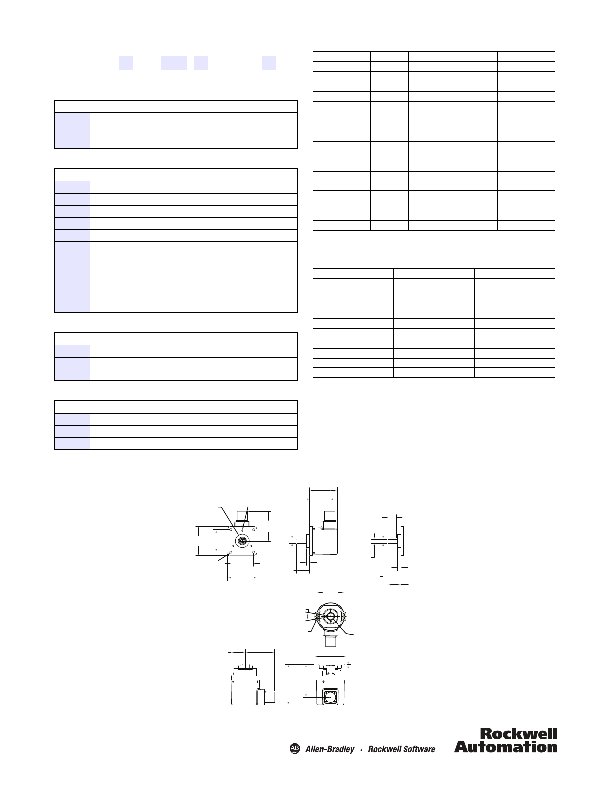
Approximate Dimensions [mm (in.)]
8-32 UNC-28 0.18 (9.57) min.
3 places 120° apart
66.5
(2.62)
4 places
52.3
(2.06)
on a 47.63 (1.875) B.C.
52.3
(2.06)
66.5 (2.62)
Square Flange, Solid Shaft
32.5
(1.28)
68.4 (2.7)
68.4
(2.7)
9.51 (0.3746)
9.51 (0.3744)
31.75 (1.25)
31.74 (1.24)
5.3 (0.21) Dia.
29.6
(1.16)
93.0
(3.7)
20°
3.3
(0.13)
75.5
(3.0)
63.4 (2.5)
46.4
(1.8)
7.6
(0.30)
63.0
(2.48)
72.0 (2.83)
19.1
(0.75)
8.71
(0.34)
9.51 (0.3746)
9.51 (0.3744)
Solid Shaft with Flat
15 (0.59) is max. bore size
smaller bores require collets
1.97
(0.08)
7.6
(0.30)
29.6
(1.16)
Hub
Shaft
2
Page 3

Accessories
Description Cat. No.
M23 17-pin Cables 2090-XXNFMF-Sxx
MS 10-pin Cables 842HR-CA-2-yy
Flexible Coupling 845-FC-x-x
2090-XXNFMF-Sxx
Pre-wired cable to an M23 DIN 17-pin connector for the encoder.
The other end of the cable is flying leads.
Flexible Couplings
xx = Cable Length
01 1 m
02 2 m
03 3 m
04 4 m
05 5 m
07 7 m
09 9 m
12 12 m
15 15 m
20 20 m
25 25 m
30 30 m
Note: Consult manufacturer’s drive manual for maximum
recommended cable length.
842HR-CA-2-yy
Pre-wired cable to an MS 10-pin connector for the encoder. The
other end of the cable is flying leads.
yy = Cable Length
01 1 m
03 3 m
05 5 m
10 10 m
20 20 m
30 30 m
High Performance Flexible Coupling
845–FC–B–B
Description
High performance flexible couplings are used to connect two
shafts, and help to reduce the effects of misalignment between
the shafts. Flexible couplings are offered in the high performance
version, with nonconductive inserts. They are of the flexible
curved beam helical type with clamping screw at both ends.
Specifications
Parallel Offset 0.51 mm (0.02 in) max.
Angular Offset 10° max.
Axial Compliance 1.58 mm (0.06 in) max.
Construction Aluminum with a fiberglass insert
Available catalog numbers for this encoder:
845-FC-B-B
845-FC-B-C
845-FC-B-R
845-FC-B-T
845-FC-A-B
845-FC-R-B
Product Selection
845 — FC — B—B
ab
a
Smallest Bore Diameter
Code Description
A1/4 inch
B3/8 inch
R6 mm
T 10 mm
b
Largest Bore Diameter
Code Description
A1/4 inch
B3/8 inch
C1/2 inch
R6 mm
T 10 mm
3
Page 4

Approximate Dimensions [mm (in.)]
X
YZ
AT TE N T IO N : The shielded cables, output
devices, and power supplies must be properly
grounded. All National Electric Code and
applicable local codes and ordinances must be
observed when wiring the system.
Angle
Parallel
Offset
AT TE N T IO N : Rigidly coupling the encoder
shaft to the machine shaft will cause a failure
in either the bearings of the encoder or the
bearings of the machine shaft.
High Performance Flexible Coupling
Dimension
Code
X 6.4 (0.25) 9.5 (0.375) 12.7 (0.50) 6 1 0
Y 30.56 (1.20) Dia.
Z 32 (1.25)Long
ABCRT
Flexible Shaft Couplings
Bore Size Code Letter
10000011167 Ver 01
September 2012
 Loading...