

Page 1
Installation Instructions
IMPORTANT: SAVE THESE INSTRUCTIONS FOR FUTURE USE.
842E EtherNet/IP™ Encoders
High Resolution with DLR
Description
The 842E is an ultra-high resolution encoder with EtherNet/IP inter face. These encoders
provide 18-bit single-turn resolution and 30-bit multi-turn resolution. The EtherNet/IP
encoder is targeted for high performance and reliability in harsh industrial
environments. Encoder includes an embedded EtherNet/IP switch to connect additional
E/IP capable product in series and/or support a Device Level Ring (DLR) for ethernet
media redundancy.
Features
• EtherNet/IP
• Embedded switch
• Hardware/software IP address setting
• Resolution up to 30 bits
• Protection class up to IP67
• Simple and fast set up
• Device Level Ring (DLR)
•Revolution divisor
• Solid and blind hollow shaft options
Configurable Parameters Typical Applications
• Counting direction • Packing machines
• Counts per resolution • Robotics
• Counts of revolution • Printing machines
• Preset value • Rotary table positioning
• Velocity unit
• IP address
ENGLISH: This instruction sheet is available in m ultiple languages at
CHINESE SIMPLIFIED:
CHINESE TRADITIONAL:
FRENCH:
GERMAN:
ITALIAN:
JAPANESE:
KOREAN:
PORTUGUESE:
SPANISH:
www.rockwellautomation.com/literature. Select the publication language before
typing in the search field.
Specifications
Certifications CE Marked for all applicable directives
Electrical
Bus Connection EtherNet/IP IEC 61784-1
Transmission Rate 10/100 MBit/s
Transmission Medium Cat-5e cable
Code Type Binary
Operating Voltage Range 10…30V
Power Con sumption 3.0 W
Resolution 262,144 (18 bit)
No. of Revolutions, max. 4,096 (12 bit)
Error Limits ±0.03°
Repeatability ±0.002°
Operating Current, max., no load;
10…30V supply
Mechanical
Moment of Inertia
Operating Speed 9,000 RPM (solid shaft ), max.
Shaft Loading Radial: 80 N max. (solid shaf t)
Permissible Shaft Movement Radial (static/dynamic): ± 0.3 / ± 0.05 mm [of drive element (blind
Bearing Lifetime
Angular Acceleration
Operating Torque 0.3 Ncm (solid shaft) @ 20 °C
Starting Torque 0.5 Ncm (solid shaft) at 20°C
Environmental
Housing Material Aluminum
Shaft Material Stainless steel
Operating Temperature [C (F)] -30… +85° (-22… +185°)
Storage Temperature [C (F)] -40… +100° (-40… +212°)
Relative Humidity 90%
Shock 100 g/6 ms
Vibrat ion 20 g/10…2000 Hz
Enclosure Type Rating IP67 (IEC 60529)
Weight 0.2 kg (0.44 lb)
Standards EN 61000-6-2 and EN 61000-6-3 EMC
Without packaging.
To condensation not permitted.
To DIN EN 60068-2-27.
To DIN EN 60068-2-6.
With mating connector inserted.
200 mA
2
(solid shaft) of the rotor
6.2 gcm
2
(blind hollow shaft) of the rotor
35 gcm
6,000 RPM (blind hollow shaft), max.
Axial: 40 N max. (solid sh aft)
hollow shaft)]
Axial (static/dynamic): ± 0.5 / ± 0.1 mm [of d rive element (blind
hollow shaft)]
9
3 x 10
revolutions
5
5 x 10
rad/s², max.
0.6 Ncm (blind hollow shaft) @ 20 °C
0.8 Ncm (blind hollow shaft) at 20°C
Publication #10000169360 Ver 02 — July 2012
Page 2
Product Selection
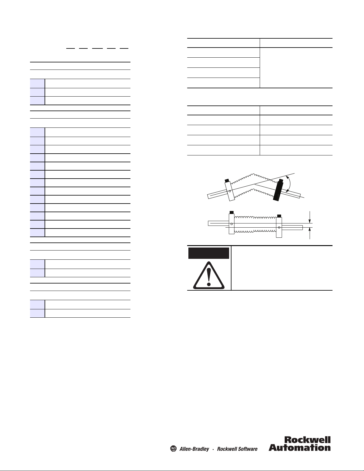
Rigidly coupling the encoder shaft to
the machine shaft will cause a failure in
either the bearings of the encoder or
the bearings of the machine shaft.
842E —SIP10 B A
abcd
Accessories
Description Note
Flexible couplings
a
Number of Turns
Code Description
S Single-turn (1 turn)
M Multi-turn (4096 turns)
b
Mechanical Interface
Code Description
1Solid shaft 3/8 in.
2 Solid shaft 3/8 in. with flat
3Solid shaft 10 mm
4 Solid shaft 10 mm with flat
5 Hollow shaft 1/4 in.
6 Hollow shaft 8 mm
7 Hollow shaft 3/8 in.
8 Hollow shaft 10 mm
9 Hollow shaft 12 mm
10 Hollow shaft 1/2 in.
11 Hollow shaft 14 mm
12 Hollow shaft 15 mm
Mounting plates
Ethernet me dia
Cordset s & patchcor ds
Suggested Mating Cables
Description Cat. No.
4-wire cable spool, robotic TPE, 100 m
M12 D-code patchcord, male/male, 1 m
DC micro QD cordset, 4-pin, 2 m
DC micro QD patchcord, 4-pin, 2 m
Flexible Shaft Couplings
For information on these products, please refer to
www.ab.com/en/epub/catalogs
1585-C4TB-S100
1585D-M4TBJM-2
889D-F4AC-2
889D-F4ACDM-2
Angle
Parallel
Oset
c
Connector
Code Description
B M12 connector
d
Resolution
Code Description
A 262,144 (18 bit) steps per revolution
ATTENTION
Publication #10000169360 Ver 02 — July 2012
Page 3

72 (2.83)
3.2
(0.13)
dia.
20°
20 (0.79)
47 (1.85)
63 (2.48) dia.
15 (0.59) min.
40 (1.57)
max.
60
(2.36)
dia.
M12x1
M12X1
68.8 (2.7)
10.3
(0.41)
9.4
(0.37)
3.4
(0.13)
68 (2.68)
71.5 (2.8)
ØX F7
120°
48
(1.89) dia.
M4 (3X)
6 (0.24) deep
25°±2°
(3X)
62.3 (2.45)
10.3 (0.41)
10
(0.39)
61.5 (2.42)
65 (2.56)
60
(2.36) dia.
M12X1
M12X1
36 (1.41)
dia. F8
19 (0.75)
ØX F7
9
(0.35)
18
(0.71)
Blind Hollow Shaft
Solid Shaft
Screw cap
Approximate Dimensions [mm (in.)]
Publication #10000169360 Ver 02 — July 2012
Page 4

Power, Control and Information Solutions Headquarters
Americas: Rockwell Automation, 1201 South Second Street, Milwaukee, WI 53204-2496 USA, Tel: (1) 414.382.2000, Fax: (1) 414.382.4444
Europe/Middle East/Africa: Rockwell Automation NV, Pegasus Park, De Kleetlaan 12a, 1831 Diegem, Belgium, Tel: (32) 2 663 0600, Fax: (32) 2 663 0640
Asia Pacic: Rockwell Automation, Level 14, Core F, Cyberport 3, 100 Cyberport Road, Hong Kong, Tel: (852) 2887 4788, Fax: (852) 2508 1846
www.rockwel lautomation.com
Pinout & Color Code
Do not use ()
ATTENTION
NET
MOD
LINK 1
LINK 2
XS
x1
x10
x100
EtherNet/IP Pinout
1
4
Pin Signal Name Color Code Pair Assignment
1TXD+White Orange
3TXD- Orange
2 RXD + White Green
4RXD- Green
LED Status
2
3
Pair 1
Pair 2
Power Supply Pinout
1
ATTENTION
Do not use
2
3
4
Pin Signal Name Color Code Pair Assignment
1Vs Brown
2— White
3 GND Blue 0V DC (ground)
4— Black
Applying power to pins 2 and 4 will damage the encoder.
Supply voltage
10…32VDC
Do not use
Do not use
Module Status LED Short Description Encoder Status LED Short Description
OFF No power OFF No power
Green Device operational Green flashing Wrong parameter
Green flashing Standby Green Device operational
Red flashing Minor fault Red flashing Minor fault
Red Major fault Red Major fault
Green/red flashing Self-test Green/red flashing Self-test
Network Status LED Short Description Link 1 Status LED Short Description
OFF No power/IP address OFF No link/power off
Green flashing No connected Green solid LINK
Green Connected Amber solid Port disabled
Red flashing Minor fault Green flashing Por t activity
Red Major fault Amber flashing Collision
Green/red flashing Self-test
Link 2 Status LED Short Description
OFF No link/power off
Green solid LINK
Amber solid Port disabled
Green flashing Port ac tivity
Amber flashing Collision
Copyright 2012 Rockwell Automation, Inc. All rights reserved. Printed in USA.
10000169360
842E-IN001A-EN-P
Ver 02 — July 2012
 Loading...