

Rockwell Automation 5094-OB16, 5094-IB16S, 5094-OB16XT, 5094-OB16S, 5094-IB16 User Manual
...Page 1

User Manual
Original Instructions
FLEX 5000 Standard and Safety Digital I/O Modules
Catalog Numbers 5094-IB16, 5094-IB16XT, 5094-IB16S, 5094-IB16SXT, 5094-OB16, 5094-OB16XT, 5094-OB16S,
5094-OB16SXT, 5094-OW8I, 5094-OW8IXT
Page 2

Important User Information
Read this document and the documents listed in the additional resources section about installation, configuration, and
operation of this equipment before you install, configure, operate, or maintain this product. Users are required to
familiarize themselves with installation and wiring instructions in addition to requirements of all applicable codes, laws,
and standards.
Activities including installation, adjustments, putting into service, use, assembly, disassembly, and maintenance are
required to be carried out by suitably trained personnel in accordance with applicable code of practice.
If this equipment is used in a manner not specified by the manufacturer, the protection provided by the equipment may
be impaired.
In no event will Rockwell Automation, Inc. be responsible or liable for indirect or consequential damages resulting from
the use or application of this equipment.
The examples and diagrams in this manual are included solely for illustrative purposes. Because of the many variables and
requirements associated with any particular installation, Rockwell Automation, Inc. cannot assume responsibility or
liability for actual use based on the examples and diagrams.
No patent liability is assumed by Rockwell Automation, Inc. with respect to use of information, circuits, equipment, or
software described in this manual.
Reproduction of the contents of this manual, in whole or in part, without written permission of Rockwell Automation,
Inc., is prohibited.
Throughout this manual, when necessary, we use notes to make you aware of safety considerations.
WARNING: Identifies information about practices or circumstances that can cause an explosion in a hazardous
environment, which may lead to personal injury or death, property damage, or economic loss.
ATTENTION: Identifies information about practices or circumstances that can lead to personal injury or death, property
damage, or economic loss. Attentions help you identify a hazard, avoid a hazard, and recognize the consequence.
IMPORTANT Identifies information that is critical for successful application and understanding of the product.
Labels may also be on or inside the equipment to provide specific precautions.
SHOCK HAZARD: Labels may be on or inside the equipment, for example, a drive or motor, to alert people that dangerous
voltage may be present.
BURN HAZARD: Labels may be on or inside the equipment, for example, a drive or motor, to alert people that surfaces may
reach dangerous temperatures.
ARC FLASH HAZARD: Labels may be on or inside the equipment, for example, a motor control center, to alert people to
potential Arc Flash. Arc Flash will cause severe injury or death. Wear proper Personal Protective Equipment (PPE). Follow ALL
Regulatory requirements for safe work practices and for Personal Protective Equipment (PPE).
Page 3

Digital I/O Module Operation
in a Logix 5000 Control System
Table of Contents
Preface
Summary of Changes . . . . . . . . . . . . . . . . . . . . . . . . . . . . . . . . . . . . . . . . . . . 9
Manual Conventions . . . . . . . . . . . . . . . . . . . . . . . . . . . . . . . . . . . . . . . . . . . 9
Graphics Indicate Feature Support. . . . . . . . . . . . . . . . . . . . . . . . . . . . . . 10
Terminology. . . . . . . . . . . . . . . . . . . . . . . . . . . . . . . . . . . . . . . . . . . . . . . . . . 11
Additional Resources . . . . . . . . . . . . . . . . . . . . . . . . . . . . . . . . . . . . . . . . . . 12
Chapter 1
Controller and Software Compatibility . . . . . . . . . . . . . . . . . . . . . . . . . 17
Controller Compatibility . . . . . . . . . . . . . . . . . . . . . . . . . . . . . . . . . . 17
Firmware and Software Compatibility. . . . . . . . . . . . . . . . . . . . . . . 18
Secure Access to the System . . . . . . . . . . . . . . . . . . . . . . . . . . . . . . . . . . . . 19
Types of Modules . . . . . . . . . . . . . . . . . . . . . . . . . . . . . . . . . . . . . . . . . . . . . 19
Module Overview . . . . . . . . . . . . . . . . . . . . . . . . . . . . . . . . . . . . . . . . . . . . . 20
Ownership . . . . . . . . . . . . . . . . . . . . . . . . . . . . . . . . . . . . . . . . . . . . . . . . . . . 22
Multiple Owners of FLEX 5000 Input Modules . . . . . . . . . . . . . 22
Configuration Changes in an Input Module
with Multiple Owners . . . . . . . . . . . . . . . . . . . . . . . . . . . . . . . . . . . . . . . . . 23
Construct a 5094 FLEX 5000 I/O System. . . . . . . . . . . . . . . . . . . . . . . 24
FLEX 5000 I/O System Power . . . . . . . . . . . . . . . . . . . . . . . . . . . . . 24
Before You Begin. . . . . . . . . . . . . . . . . . . . . . . . . . . . . . . . . . . . . . . . . . . . . . 25
Configuration via Logix Designer Application . . . . . . . . . . . . . . . . . . . 25
Connections for Standard I/O Modules. . . . . . . . . . . . . . . . . . . . . . . . . 26
Requested Packet Interval . . . . . . . . . . . . . . . . . . . . . . . . . . . . . . . . . . 26
Connection Types Available with FLEX 5000
Standard I/O Modules. . . . . . . . . . . . . . . . . . . . . . . . . . . . . . . . . . . . . 27
Data Types Available with FLEX 5000 Standard
I/O Modules. . . . . . . . . . . . . . . . . . . . . . . . . . . . . . . . . . . . . . . . . . . . . . 27
Connections for Safety I/O Modules . . . . . . . . . . . . . . . . . . . . . . . . . . . 28
‘Configured By’ Options for Safety I/O Modules. . . . . . . . . . . . . 29
Data Types Available with FLEX 5000 Safety I/O Modules. . . 30
Requested Packet Interval . . . . . . . . . . . . . . . . . . . . . . . . . . . . . . . . . . 30
Connection Over an EtherNet/IP Network . . . . . . . . . . . . . . . . . . . . . 32
Input Module Operation . . . . . . . . . . . . . . . . . . . . . . . . . . . . . . . . . . . . . . 32
Trigger Events . . . . . . . . . . . . . . . . . . . . . . . . . . . . . . . . . . . . . . . . . . . . . . . . 33
Output Module Operation . . . . . . . . . . . . . . . . . . . . . . . . . . . . . . . . . . . . 33
Listen Only Mode. . . . . . . . . . . . . . . . . . . . . . . . . . . . . . . . . . . . . . . . . . . . . 35
Protected Operations. . . . . . . . . . . . . . . . . . . . . . . . . . . . . . . . . . . . . . . . . . 36
Considerations Specific to Safety Modules . . . . . . . . . . . . . . . . . . . . . . 36
Single-channel or Dual-channel Mode. . . . . . . . . . . . . . . . . . . . . . . 37
Use with Safety Controllers . . . . . . . . . . . . . . . . . . . . . . . . . . . . . . . . . . . . 37
Determine Conformity . . . . . . . . . . . . . . . . . . . . . . . . . . . . . . . . . . . . 38
Obtain Firmware . . . . . . . . . . . . . . . . . . . . . . . . . . . . . . . . . . . . . . . . . . 38
Safety Precautions . . . . . . . . . . . . . . . . . . . . . . . . . . . . . . . . . . . . . . . . . 39
Safety Application Requirements . . . . . . . . . . . . . . . . . . . . . . . . . . . 40
Rockwell Automation Publication 5094-UM001C-EN-P - April 2019 3
Page 4

Table of Contents
Safe State . . . . . . . . . . . . . . . . . . . . . . . . . . . . . . . . . . . . . . . . . . . . . . . . . 41
Configuration Signature and Ownership . . . . . . . . . . . . . . . . . . . . 42
Reset FLEX 5000 I/O Safety Modules to Out-of-Box State . . . 43
Chapter 2
Common Digital I/O Module
Features
Input Module Compatibility. . . . . . . . . . . . . . . . . . . . . . . . . . . . . . . . . . . 46
Output Module Capability. . . . . . . . . . . . . . . . . . . . . . . . . . . . . . . . . . . . . 46
Producer/Consumer Communication . . . . . . . . . . . . . . . . . . . . . . . . . . 46
Module Data Quality Reporting. . . . . . . . . . . . . . . . . . . . . . . . . . . . . . . . 47
Software Configurable. . . . . . . . . . . . . . . . . . . . . . . . . . . . . . . . . . . . . . . . . 48
Fault and Status Reporting. . . . . . . . . . . . . . . . . . . . . . . . . . . . . . . . . . . . . 48
Module Firmware . . . . . . . . . . . . . . . . . . . . . . . . . . . . . . . . . . . . . . . . . . . . . 48
Module Inhibiting . . . . . . . . . . . . . . . . . . . . . . . . . . . . . . . . . . . . . . . . . . . . 49
Electronic Keying . . . . . . . . . . . . . . . . . . . . . . . . . . . . . . . . . . . . . . . . . . . . . 50
Module Firmware . . . . . . . . . . . . . . . . . . . . . . . . . . . . . . . . . . . . . . . . . . . . . 51
Chapter 3
Input Module Features Data Transfer at RPI . . . . . . . . . . . . . . . . . . . . . . . . . . . . . . . . . . . . . . . . . . 53
Software Configurable Input Filters and Delays. . . . . . . . . . . . . . . . . . 54
Field Power Loss Detection . . . . . . . . . . . . . . . . . . . . . . . . . . . . . . . . . . . . 54
Fault and Status Reporting. . . . . . . . . . . . . . . . . . . . . . . . . . . . . . . . . . . . . 55
Chapter 4
Output Module Features Features Specific to All FLEX 5000 Output Modules . . . . . . . . . . . . 57
Output State Change Time . . . . . . . . . . . . . . . . . . . . . . . . . . . . . . . . 57
Configurable Point-level Output State in Program Mode or
Fault Mode . . . . . . . . . . . . . . . . . . . . . . . . . . . . . . . . . . . . . . . . . . . . . . . 58
Connection Fault Handling . . . . . . . . . . . . . . . . . . . . . . . . . . . . . . . . 58
Output Behavior Immediately After a Connection Fault. . . . . . 59
Output State Once Connection Is Re-established . . . . . . . . . . . . 59
Forcing . . . . . . . . . . . . . . . . . . . . . . . . . . . . . . . . . . . . . . . . . . . . . . . . . . . 59
Enable Forces . . . . . . . . . . . . . . . . . . . . . . . . . . . . . . . . . . . . . . . . . . . . . 60
Disable or Remove a Force . . . . . . . . . . . . . . . . . . . . . . . . . . . . . . . . . 60
Check Force Status . . . . . . . . . . . . . . . . . . . . . . . . . . . . . . . . . . . . . . . . 61
GSV Instruction. . . . . . . . . . . . . . . . . . . . . . . . . . . . . . . . . . . . . . . . . . . 61
Data Echo . . . . . . . . . . . . . . . . . . . . . . . . . . . . . . . . . . . . . . . . . . . . . . . . 62
Field Power Loss Detection . . . . . . . . . . . . . . . . . . . . . . . . . . . . . . . . 62
Fault and Status Reporting . . . . . . . . . . . . . . . . . . . . . . . . . . . . . . . . . 62
Features Specific to Only Standard and Safety Solid-state
Output Modules . . . . . . . . . . . . . . . . . . . . . . . . . . . . . . . . . . . . . . . . . . . . . . 63
No Load Detection . . . . . . . . . . . . . . . . . . . . . . . . . . . . . . . . . . . . . . . . 63
Short-Circuit Protection . . . . . . . . . . . . . . . . . . . . . . . . . . . . . . . . . . . 64
Thermal Shutoff . . . . . . . . . . . . . . . . . . . . . . . . . . . . . . . . . . . . . . . . . . 65
Features Specific to Only 5094-OB16 and
5094-OB16XT Modules. . . . . . . . . . . . . . . . . . . . . . . . . . . . . . . . . . . . . . . 66
Time-scheduled Output Control . . . . . . . . . . . . . . . . . . . . . . . . . . . 66
4 Rockwell Automation Publication 5094-UM001C-EN-P - April 2019
Page 5

Table of Contents
Use a MAOC Instruction with a 5094-OB16 or
5094-OB16XT Standard Output Module . . . . . . . . . . . . . . . . . . . 67
Feature Specific to Only 5094-OW8I and
5094-OW8IXT Modules . . . . . . . . . . . . . . . . . . . . . . . . . . . . . . . . . . . . . . 69
Isolated Output . . . . . . . . . . . . . . . . . . . . . . . . . . . . . . . . . . . . . . . . . . . 69
Chapter 5
Safety I/O Module Features Safety Input Module Features . . . . . . . . . . . . . . . . . . . . . . . . . . . . . . . . . . 71
Safety Application Suitability Levels . . . . . . . . . . . . . . . . . . . . . . . . 71
Input Modules in CIP Safety Systems . . . . . . . . . . . . . . . . . . . . . . . 72
Use Test Output with a Safety Input . . . . . . . . . . . . . . . . . . . . . . . . 73
Single-channel Mode . . . . . . . . . . . . . . . . . . . . . . . . . . . . . . . . . . . . . . 75
Safety Input Fault Reset. . . . . . . . . . . . . . . . . . . . . . . . . . . . . . . . . . . . 76
Safety Input Delay. . . . . . . . . . . . . . . . . . . . . . . . . . . . . . . . . . . . . . . . . 77
Safety Output Module Features . . . . . . . . . . . . . . . . . . . . . . . . . . . . . . . . 79
Safety Application Suitability Levels . . . . . . . . . . . . . . . . . . . . . . . . 79
Output Module in CIP Safety Systems . . . . . . . . . . . . . . . . . . . . . . 80
Safety and Safety Pulse Test Mode . . . . . . . . . . . . . . . . . . . . . . . . . . 81
Single-channel Mode . . . . . . . . . . . . . . . . . . . . . . . . . . . . . . . . . . . . . . 82
Dual-channel Mode . . . . . . . . . . . . . . . . . . . . . . . . . . . . . . . . . . . . . . . 83
Surge Capability of Safety Output . . . . . . . . . . . . . . . . . . . . . . . . . . 84
Safety Output Fault Reset . . . . . . . . . . . . . . . . . . . . . . . . . . . . . . . . . . 85
Fault and Status Reporting. . . . . . . . . . . . . . . . . . . . . . . . . . . . . . . . . . . . . 86
Chapter 6
Configure the Standard Module Before You Begin. . . . . . . . . . . . . . . . . . . . . . . . . . . . . . . . . . . . . . . . . . . . . . 88
Create a New Module . . . . . . . . . . . . . . . . . . . . . . . . . . . . . . . . . . . . . . . . . 88
Discover Modules . . . . . . . . . . . . . . . . . . . . . . . . . . . . . . . . . . . . . . . . . 89
New Module . . . . . . . . . . . . . . . . . . . . . . . . . . . . . . . . . . . . . . . . . . . . . . 91
Edit the Module Configuration Common Categories . . . . . . . . . . . . 93
General Category. . . . . . . . . . . . . . . . . . . . . . . . . . . . . . . . . . . . . . . . . . 93
Connection Category. . . . . . . . . . . . . . . . . . . . . . . . . . . . . . . . . . . . . . 95
Module Info Category . . . . . . . . . . . . . . . . . . . . . . . . . . . . . . . . . . . . . 96
Edit 5094-IB16 Module Configuration Categories. . . . . . . . . . . . . . . 97
Counters Category . . . . . . . . . . . . . . . . . . . . . . . . . . . . . . . . . . . . . . . . 97
Points Category . . . . . . . . . . . . . . . . . . . . . . . . . . . . . . . . . . . . . . . . . . . 98
Events Category . . . . . . . . . . . . . . . . . . . . . . . . . . . . . . . . . . . . . . . . . . 100
Time Sync Category . . . . . . . . . . . . . . . . . . . . . . . . . . . . . . . . . . . . . . 102
Edit 5094-OB16 Module Configuration Categories. . . . . . . . . . . . . 103
Points Category . . . . . . . . . . . . . . . . . . . . . . . . . . . . . . . . . . . . . . . . . . 103
Edit 5094-OW8I Module Configuration Categories . . . . . . . . . . . . 104
Points Category . . . . . . . . . . . . . . . . . . . . . . . . . . . . . . . . . . . . . . . . . . 104
View the Module Tags. . . . . . . . . . . . . . . . . . . . . . . . . . . . . . . . . . . . . . . . 105
Rockwell Automation Publication 5094-UM001C-EN-P - April 2019 5
Page 6

Table of Contents
Chapter 7
Configure and Replace Safety
Modules
Before You Begin. . . . . . . . . . . . . . . . . . . . . . . . . . . . . . . . . . . . . . . . . . . . . 108
Create a New Module . . . . . . . . . . . . . . . . . . . . . . . . . . . . . . . . . . . . . . . . 108
New I/O Module. . . . . . . . . . . . . . . . . . . . . . . . . . . . . . . . . . . . . . . . . 108
Edit the Module Configuration Common Categories . . . . . . . . . . . 110
General Category. . . . . . . . . . . . . . . . . . . . . . . . . . . . . . . . . . . . . . . . . 111
Connection Category. . . . . . . . . . . . . . . . . . . . . . . . . . . . . . . . . . . . . 113
Safety Category. . . . . . . . . . . . . . . . . . . . . . . . . . . . . . . . . . . . . . . . . . . 114
Module Info Category . . . . . . . . . . . . . . . . . . . . . . . . . . . . . . . . . . . . 115
Edit the 5094-IB16S or
5094-IB16SXT Module Configuration Categories. . . . . . . . . . . . . . 115
Input Points Category . . . . . . . . . . . . . . . . . . . . . . . . . . . . . . . . . . . . 115
Test Output Points Category. . . . . . . . . . . . . . . . . . . . . . . . . . . . . . 116
Edit the 5094-OB16S or 5094-OB16SXT Module
Configuration Category . . . . . . . . . . . . . . . . . . . . . . . . . . . . . . . . . . . . . . 117
View the Module Tags. . . . . . . . . . . . . . . . . . . . . . . . . . . . . . . . . . . . . . . . 117
Replace a Module . . . . . . . . . . . . . . . . . . . . . . . . . . . . . . . . . . . . . . . . . . . . 118
Set the SNN Manually . . . . . . . . . . . . . . . . . . . . . . . . . . . . . . . . . . . . 119
Reset to Out-of-Box Configuration . . . . . . . . . . . . . . . . . . . . . . . . 120
Replace a Module in a Logix 5000 System . . . . . . . . . . . . . . . . . . 121
Appendix A
Troubleshoot Your Module SA Power Indicator . . . . . . . . . . . . . . . . . . . . . . . . . . . . . . . . . . . . . . . . . . 124
Module Status Indicator . . . . . . . . . . . . . . . . . . . . . . . . . . . . . . . . . . . . . . 125
FLEX 5000 Digital Input Modules Status Indicators . . . . . . . . . . . . 126
FLEX 5000 Output Modules Status Indicators . . . . . . . . . . . . . . . . . 127
FLEX 5000 Safety Input Modules Status Indicators. . . . . . . . . . . . . 129
FLEX 5000 Safety Output Modules Status Indicators . . . . . . . . . . . 130
Use the Logix Designer Application for Troubleshooting. . . . . . . . 131
Warning Signal in the I/O Configuration Tree . . . . . . . . . . . . . 131
Status and Fault Information in Module
Properties Categories . . . . . . . . . . . . . . . . . . . . . . . . . . . . . . . . . . . . . 132
Logix Designer Application Tag Editor. . . . . . . . . . . . . . . . . . . . . 136
Appendix B
Module Tag Definitions Tag Name Conventions . . . . . . . . . . . . . . . . . . . . . . . . . . . . . . . . . . . . . . 138
Access the Tags . . . . . . . . . . . . . . . . . . . . . . . . . . . . . . . . . . . . . . . . . . . . . . 138
5094-IB16 Module Tags . . . . . . . . . . . . . . . . . . . . . . . . . . . . . . . . . . . . . . 139
Configuration Tags. . . . . . . . . . . . . . . . . . . . . . . . . . . . . . . . . . . . . . . 139
Input Tags . . . . . . . . . . . . . . . . . . . . . . . . . . . . . . . . . . . . . . . . . . . . . . . 140
Output Tags . . . . . . . . . . . . . . . . . . . . . . . . . . . . . . . . . . . . . . . . . . . . . 143
Event Input Tags . . . . . . . . . . . . . . . . . . . . . . . . . . . . . . . . . . . . . . . . . 144
Event Output Tags . . . . . . . . . . . . . . . . . . . . . . . . . . . . . . . . . . . . . . . 145
5094-IB16S and 5094-IB16SXT Module Tags . . . . . . . . . . . . . . . . . 147
Input Tags . . . . . . . . . . . . . . . . . . . . . . . . . . . . . . . . . . . . . . . . . . . . . . . 147
Test Output Tags . . . . . . . . . . . . . . . . . . . . . . . . . . . . . . . . . . . . . . . . 148
6 Rockwell Automation Publication 5094-UM001C-EN-P - April 2019
Page 7

Application/Wiring Examples
for Safety I/O Modules
Table of Contents
Safety Output Tags . . . . . . . . . . . . . . . . . . . . . . . . . . . . . . . . . . . . . . . 148
5094-OB16 Module Tags. . . . . . . . . . . . . . . . . . . . . . . . . . . . . . . . . . . . . 149
Configuration Tags. . . . . . . . . . . . . . . . . . . . . . . . . . . . . . . . . . . . . . . 149
Input Tags . . . . . . . . . . . . . . . . . . . . . . . . . . . . . . . . . . . . . . . . . . . . . . . 150
Output Tags . . . . . . . . . . . . . . . . . . . . . . . . . . . . . . . . . . . . . . . . . . . . . 151
5094-OB16S and 5094-OB16SXT Module Tags . . . . . . . . . . . . . . . 152
Input Tags . . . . . . . . . . . . . . . . . . . . . . . . . . . . . . . . . . . . . . . . . . . . . . . 152
Safety Output Tags . . . . . . . . . . . . . . . . . . . . . . . . . . . . . . . . . . . . . . . 153
5094-OW8I Module Tags . . . . . . . . . . . . . . . . . . . . . . . . . . . . . . . . . . . . 153
Configuration Tags. . . . . . . . . . . . . . . . . . . . . . . . . . . . . . . . . . . . . . . 153
Input Tags . . . . . . . . . . . . . . . . . . . . . . . . . . . . . . . . . . . . . . . . . . . . . . . 154
Output Tags . . . . . . . . . . . . . . . . . . . . . . . . . . . . . . . . . . . . . . . . . . . . . 154
Appendix C
5094-IB16S and 5094-IB16SXT Module Wiring Diagrams. . . . . . 156
5094-OB16S and 5094-OB16SXT Module Wiring Diagrams . . . 161
Appendix D
Safety Data for I/O Modules FLEX 5000 I/O Safety Input Module Safety Data . . . . . . . . . . . . . . 164
FLEX 5000 I/O Safety Output Module Safety Data. . . . . . . . . . . . . 164
Rockwell Automation Publication 5094-UM001C-EN-P - April 2019 7
Page 8

Table of Contents
Notes:
8 Rockwell Automation Publication 5094-UM001C-EN-P - April 2019
Page 9

Preface
This manual describes how to use FLEX 5000™ standard and safety I/O
modules in Logix 5000™ control systems.
Make sure that you are familiar with the following:
• Use of a controller in a Logix 5000 control system
• Use of an EtherNet/IP™ network, if the digital I/O modules are installed
in a remote location from the controller that is accessible via the
EtherNet/IP network
• Use of safety systems
• Studio 5000 Logix Designer® environment
Summary of Changes
Manual Conventions
This manual was revised to add information about FLEX 5000 I/O safety
modules. This table indicates where new content exists in the manual.
Top ic Pag e
Added safety catalog numbers 5094-IB16S, 5094-IB16SXT, 5094-OB16S, 5094-OB16SXT Throughout
Added Chapter 5
Added Chapter 7, Configure and Replace Safety Modules 107
Added Appendix C, Application/Wiring Examples for Safety I/O Modules
Added Appendix D, Safety Data for I/O Modules 163
, Safety I/O Module Features 71
155
Within this manual, we simplified product names and added product icons for
your ease of use.
We us e standard module to indicate a module that does not have functional
safety capability. We use safety module to indicate a module with functional
safety capability (catalog numbers ending in “S” or “SXT”). Further, we use
FLEX 5000 I/O module to indicate when a concept or task applies to both the
standard and safety digital I/O modules.
Rockwell Automation Publication 5094-UM001C-EN-P - April 2019 9
Page 10

Preface
Graphics Indicate Feature Support
Throughout this manual, graphics appear with section titles to indicate the
digital I/O modules that support the feature that is described in that section.
If both standard and safety modules support a feature, you see icons for both
types.
If only one type of module, standard or safety, supports a feature, you see only
one type of icon.
10 Rockwell Automation Publication 5094-UM001C-EN-P - April 2019
Page 11

Preface
Terminology
Abbreviation Full Term Definition
1oo2 One out of Two Identifies the programmable electronic controller architecture.
CIP™ Common Industrial Protocol An industrial communication protocol that is used by Logix 5000-based automation
CIP Sync™ Common Industrial Protocol Synchronization CIP Sync provides the increased control coordination needed for control applications
CIP Safety™ Common Industrial Protocol – Safety Certified SIL-rated version of CIP.
— Connection Logical communication channel for communication between nodes. Connections are
CL Claim Limit The maximum safety integrity level (SIL) that can be achieved.
DC Diagnostic Coverage The ratio of the detected failure rate to the total failure rate.
EDS Electronic Data Sheet, A template that is used in RSNetWorx™ software to display the configuration
EN European Norm. The official European Standard.
ESS Energy Storage System Used for backup for memory retention at powerdown on Compact GuardLogix® 5380
GSV Get System Value A ladder logic instruction that retrieves specified controller status information and
MTTF Mean Time To Failure The length of time that a device or other product is expected to remain reliable in
— Multicast The transmission of information from one sender to multiple receivers.
NAT Network Address Translation The translation of an Internet Protocol (IP) address to another IP address on another
ODVA Open DeviceNet Vendor Association A nonprofit association of vendors that are established for the promotion of CIP
PC Personal computer Computer that is used to interface with and control a Logix-based system via the
PFD Probability of Failure on Demand The average probability of a system to fail to perform its design function on demand.
PFH Average frequency of a dangerous failure per hour The probability of a system to have a dangerous failure occur per hour.
PL Performance Level ISO 13849-1 safety rating.
— Proof test Periodic test that detects f ailures in a safety-related system so that, if necessary, the
— Safety (devices) Devices or portions of devices that have functional safety capability.
SIL Safety Integrity Level A relative level of risk-reduction provided by a safety function, or to specify a target
SNN Safety Network Number A unique number that identifies a section of a safety network.
SRT Safety Reaction Time A consideration of delays or latencies within the safety system.
SSV Set System Value A ladder logic instruction that sets controller system data.
— Standard (devices) Devices or portions of devices that do not have functional safety capability.
— Unicast The transmission of information from one sender to one receiver.
This table defines terms that are used in this manual.
systems on EtherNet/IP™, ControlNet®, and DeviceNet® communication networks.
where absolute time synchronization is vital to achieve real-time synchronization
between distributed intelligent devices and systems.
maintained and controlled between masters and slaves.
parameters, I/O data profile, and connection-type support for a given I/O module.
RSNetWorx software uses these simple text files to identify products and commission
them on a network.
controllers. The ESS is inside the controller and cannot be removed.
places it in a destination tag.
operation.
network.
networks.
Studio 5000® environment.
system can be restored to an as-new condition or as close as practical to this condition.
level of risk reduction.
Rockwell Automation Publication 5094-UM001C-EN-P - April 2019 11
Page 12

Preface
Additional Resources
These documents contain additional information concerning related products
from Rockwell Automation.
Table 1 - Additional Resources
Resource Description
FLEX 5000 I/O Modules Specifications Technical Data,
publication 5094-TD001
FLEX 5000 EtherNet/IP Adapters with RJ45 Ports
Installation Instructions, publication 5094-IN001
FLEX 5000 EtherNet/IP Adapters with SFP Support
Installation Instructions, publication 5094-IN002
FLEX 5000 Digital 16-point Sinking Input Modules
Installation Instructions, publication 5094-IN003
FLEX 5000 Digital 16-point Sourcing Output Modules
Installation Instructions, publication 5094-IN004
FLEX 5000 Digital 8-point Isolated Relay Output Modules
Installation Instructions, publication 5094-IN005
FLEX 5000 Analog 8-channel Current/Voltage Input
Modules Installation Instructions, publication
5094-IN006
FLEX 5000 Analog 8-channel Current/Voltage Output
Modules Installation Instructions, publication
5094-IN007
FLEX 5000 Analog 8-channel Current/Voltage/RTD/
Thermocouple Input Modules Installation Instructions,
publication 5094-IN008
FLEX 5000 High-speed Counter I/O Modules Installation
Instructions, publication 5094-IN009
FLEX 5000 Terminal Base Assembly Modules Installation
Instructions, publication 5094-IN010
FLEX 5000 Digital 16-point Sinking Safety Input
Modules Installation Instructions, publication
5094-IN012
FLEX 5000 Digital 16-point Sourcing Safety Output
Modules Installation Instructions, publication
5094-IN013
FLEX 5000 Analog I/O Modules User Manual, publication
5094-UM002
FLEX 5000 High-speed Counter I/O Modules User
Manual, publication 5094-UM003
CompactLogix 5380 Controllers User Manual,
publication 5069-UM001
EtherNet/IP Communication Modules in 5000 Series
Control Systems User Manual, publication ENET-UM004
Integrated Architecture and CIP Sync Configuration
Application Technique, publication IA-AT003
Electronic Keying in Logix5000 Control Systems
Application Technique, publication LO GIX -AT0 01
Logix5000 Controllers Tasks, Programs, and Routines
Programming Manual, publication 1756-PM005
Position-based Output Control w ith the MAOC
Instruction, publication 1756-AT017
Provides specifications for FLEX 5000 EtherNet/IP
adapters and FLEX 5000 modules.
Describes how to install and wire the 5094-AENTR,
5094-AENTRXT, 5094-AEN2TR, and 5094-AEN2TRXT
EtherNet/IP adapters.
Describes how to install and wire the 5094-AENSFPRXT
and 5094-AEN2SFPRXT EtherNet/IP adapters.
Describes how to install and wire the 5094-IB16 and
5094-IB16XT digital input modules.
Describes how to install and wire the 5094-OB16 and
5094-OB16XT digital output modules.
Describes how to install and wire the 5094-OW8I and
5094-OW8IXT digital output modules.
Describes how to install and wire the 5094-IF8 and
5094-IF8XT analog input modules.
Describes how to install and wire the 5094-OF8 and
5094-OF8XT analog output modules.
Describes how to install and wire the 5094-IY8 and
5094-IY8XT analog input modules.
Describes how to install and wire the 5094-HSC and
5094-HSCXT high-speed counter I/O modules.
Describes how to install and wire the terminal base
assemblies for the FLEX 5000 system.
Describes how to install and wire the 5094-IB16S and
5094-IB16SXT digital safety input modules.
Describes how to install and wire the 5094-OB16S and
5094-OB16SXT digital safety output modules.
Describes how to configure, operate, and troubleshoot
FLEX 5000 analog I/O modules.
Describes how to configure, operate, and troubleshoot
FLEX 5000 high-speed counter modules.
Describes how to configure, operate, and troubleshoot
CompactLogix™ 5380 controllers.
Describes how to configure, operate, and troubleshoot
the FLEX 5000 EtherNet/IP adapters.
Provides information about CIP Sync technology and
how to synchronize clocks within the Rockwell
Automation Integrated Architecture® system.
Describes how to use electronic keying in Logix 5000
control system applications.
Provides more information on event tasks and event
task configuration.
Describes how to configure time-scheduled output
control with the MAOC instruction.
12 Rockwell Automation Publication 5094-UM001C-EN-P - April 2019
Page 13

Table 1 - Additional Resources
Preface
Industrial Automation Wiring and Grounding
Guidelines, publication 1770-4.1
Product Certifications website,
http://www.rockwellautomation.com/
rockwellautomation/certification/overview.page
SISTEMA software utility,
http://marketing.rockwellautomation.com/safety/en/
Sistema_Download
Provides general guidelines for installing a
Rockwell Automation industrial system.
Provides declarations of conformity, certificates, and
other certification details.
The Rockwell Automation SISTEMA data library is
available for download, together with a link to the
SISTEMA download site.
You can view or download publications at
http://www.rockwellautomation.com/global/literature-library/overview.page
To order paper copies of technical documentation, contact your local
Allen-Bradley distributor or Rockwell Automation sales representative.
.
Rockwell Automation Publication 5094-UM001C-EN-P - April 2019 13
Page 14

Preface
Notes:
14 Rockwell Automation Publication 5094-UM001C-EN-P - April 2019
Page 15

Digital I/O Module Operation in a Logix 5000 Control System
Top ic Pag e
Controller and Software Compatibility 17
Before You Begin 25
Secure Access to the System 19
Types of Modules 19
Module Overview 20
Ownership 22
Construct a 5094 FLEX 5000 I/O System 24
Configuration via Logix Designer Application 25
Connections for Standard I/O Modules 26
Connections for Safety I/O Modules 28
Connection Over an EtherNet/IP Network 32
Input Module Operation 32
Output Module Operation 33
Listen Only Mode 35
Protected Operations 36
Considerations Specific to Safety Modules 36
Use with Safety Controllers 37
Chapter 1
IMPORTANT You cannot use FLEX 5000™ I/O modules with all Logix 5000™ controllers.
For example, you can use FLEX 5000 I/O modules with CompactLogix™ 5380
and ControlLogix® 5580 controllers but not with CompactLogix 5370 and
ControlLogix 5570 controllers.
You can use FLEX 5000 I/O modules with Logix 5000 controllers as
remote I/O modules only.
Throughout this publication, the term Logix 5000 controller refers to the
controllers with which you can use FLEX 5000 I/O modules in a given
capacity. The term does not refer to all Logix 5000 controllers.
For the most current information on the Logix 5000 controllers with which
you can use FLEX 5000 I/O modules, see the product description
at http://www.ab.com
Rockwell Automation Publication 5094-UM001C-EN-P - April 2019 15
.
Page 16

Chapter 1 Digital I/O Module Operation in a Logix 5000 Control System
STATUS
NET
LINK 1
LINK 2
5094-AENTR
EtherNet/IP™ Adapter
FLEX 5000TM I/O
PRP
DLR
POWER
X100
X10
X1
IP ADDRESS
STATUS
POWER
DIGITAL 16 INPUT 24 VDC
5094-IB16
1
1
TB3
FLEX 5000TM I/O
0 1 2 3 4 5 6 7 8 9 10 11 12 13 14 15
STATUS
POWER
DIGITAL 16 OUTPUT 24 VDC
5094-OB16
1
2
TB3
FLEX 5000TM I/O
0 1 2 3 4 5 6 7 8 9 10 11 12 13 14 15
STATUS
POWER
RELAY 8 OUTPUT ISOLATED
5094-OW8I
2
2
TB3W
FLEX 5000TM I/O
0 1 2 3 4 5 6 7
5069-L340ERM
EtherNet/IP Network
5094 Standard I/O
5094-AENTR
Logix 5000 controllers use FLEX 5000 standard and safety I/O modules to
control devices in a control system. The controllers access the modules over an
EtherNet/IP™ network. FLEX 5000 I/O modules use terminal base (TB)
assemblies to connect field-side wiring.
FLEX 5000 I/O modules use the Producer/Consumer network communication
model. This communication is an intelligent data exchange between modules and
other system devices in which each module produces data without first being
polled.
You use FLEX 5000 I/O modules as remote I/O modules that are accessible via
an EtherNet/IP network. The modules are installed to the right of a FLEX 5000
EtherNet/IP adapter.
Logix 5000 controllers can exchange data with the modules over the network.
Figure 1
shows a standard controller with standard I/O modules. Standard
controllers do not support safety I/O modules.
Figure 1 - FLEX 5000 Standard I/O Modules in a Logix 5000 Control System
16 Rockwell Automation Publication 5094-UM001C-EN-P - April 2019
Page 17

Digital I/O Module Operation in a Logix 5000 Control System Chapter 1
STATUS
NET
LINK 1
LINK 2
5094-AENTR
EtherNet/IP™ Adapter
FLEX 5000TM I/O
PRP
DLR
POWER
X100
X10
X1
IP ADDRESS
SIL2 CPU
5069-L3100ERMS2
Compact GuardLogix
SA Power
MOD Power
STATUS
POWER
RELAY 8 OUTPUT ISOLATED
5094-OW8I
2
2
TB3W
FLEX 5000TM I/O
0 1 2 3 4 5 6 7
STATUS
POWER
SAFETY DIGITAL 16 INPUT 24 VDC
5094-IB16S
5
5
TB3I
FLEX 5000TM I/O
0 1 2 3 4 5 6 7 8 9 10 11 12 13 14 15
STATUS
POWER
5094-OB16S
5
1
TB3I
FLEX 5000TM I/O
0 1 2 3 4 5 6 7 8 9 10 11 12 13 14 15
SAFETY DIGITAL 16 OUTPUT 24 VDC
5094 Standard I/O5094 Safety I/O5094-AENTREtherNet/IP Network5069-L5380
Figure 2 shows a safety controller with standard and safety I/O modules. Safety
controllers support both standard and safety I/O modules.
Figure 2 - FLEX 5000 Safety I/O Modules in a Logix 5000 Control System
Controller and Software Compatibility
Controller and programming software compatibility requirements apply when
you use FLEX 5000 standard and safety I/O modules. A module type and how it
is used affect which requirements apply.
You must also consider Logix Designer application version requirements when
you design your system. For example, you can use FLEX 5000 safety I/O
modules with only version 32 or greater of the Logix Designer application.
Controller Compatibility
Compatibility between Logix 5000 controllers and FLEX 5000 I/O modules
varies based on module type, that is, whether the module is standard or safety.
While you must pair safety I/O with a safety controller, you can also pair
standard I/O with a safety controller. For example, ControlLogix 5580
controllers are compatible with FLEX 5000 standard I/O modules.
GuardLogix® 5580 controllers are compatible with FLEX 5000 standard and
safety I/O modules.
Rockwell Automation Publication 5094-UM001C-EN-P - April 2019 17
Page 18

Chapter 1 Digital I/O Module Operation in a Logix 5000 Control System
Firmware and Software Compatibility
Ta b l e 2 describes the module compatibility requirements when you use
FLEX 5000 I/O standard and safety modules with Logix 5000 controllers.
IMPORTANT You must use adapter firmware version 3.011 or later with standard I/O
firmware version 2.011 and safety I/O modules.
Table 2 - FLEX 5000 I/O Standard and Safety Modules Controller and Software Compatibility Requirements
Controllers Logix Designer
Modules System Cat. Nos. Application Version
Standard Modules
5094-IB16, 5094-IB16XT,
5094-OB16, 5094-OB16XT,
5094-OW8I, 5094-OW8IXT
Safety Modules
5094-IB16S, 5094-IB16SXT,
5094-OB16S, 5094-OB16SXT
CompactLogix 5380 5069-L320ER, 5069-L340ERM 31.00.00 or later
5069-L306ER, 5069-L306ERM, 5069-L310ER, 5069-L310ERM, 5069-L310ER-NSE,
5069-L310ERS2, 5069-L320ERM, 5069-L330ER, 5069-L330ERM, 5069-L340ER
5069-L350ERM, 5069-L380ERM, 5069-L3100ERM 31.00.00 or later
Compact GuardLogix 5380 5069-L306ERMS2, 5069-L306ERS2, 5069-L310ERS2, 5069-L310ERMS2,
5069-L320ERS2, 5069-L320ERMS2, 5069-L330ERS2, 5069-L330ERMS2,
5069-L340ERS2, 5069-L340ERMS2, 5069-L350ERS2, 5069-L350ERMS2,
5069-L380ERS2, 5069-L380ERMS2, 5069-L3100ERS2, 5069-L3100ERMS2
ControlLogix 5580 1756-L83E, 1756-L85E 31.00.00 or later
1756-L81E, 1756-L82E, 1756-L84E 31.00.00 or later
GuardLogix 5580 1756-L81ES, 1756-L82ES, 1756-L83ES, 1756-L84ES 31.00.00 or later
Compact GuardLogix 5380 5069-L306ERMS2, 5069-L306ERS2, 5069-L310ERS2, 5069-L310ERMS2,
5069-L320ERS2, 5069-L320ERMS2, 5069-L330ERS2, 5069-L330ERMS2,
5069-L340ERS2, 5069-L340ERMS2, 5069-L350ERS2, 5069-L350ERMS2,
5069-L380ERS2, 5069-L380ERMS2, 5069-L3100ERS2, 5069-L3100ERMS2
GuardLogix 5580 1756-L81ES, 1756-L82ES, 1756-L83ES, 1756-L84ES 32.00.00 or later
31.00.00 or later
31.00.00 or later
32.00.00 or later
18 Rockwell Automation Publication 5094-UM001C-EN-P - April 2019
Page 19

Digital I/O Module Operation in a Logix 5000 Control System Chapter 1
STATUS
POWER
SAFETY DIGITAL 16 INPUT 24 VDC
5094-IB16S
5
5
TB3I
FLEX 5000TM I/O
0 1 2 3 4 5 6 7 8 9 10 11 12 13 14 15
STATUS
POWER
DIGITAL 16 INPUT 24 VDC
5094-IB16
1
1
TB3
FLEX 5000TM I/O
0 1 2 3 4 5 6 7 8 9 10 11 12 13 14 15
Safety Modules
Standard Modules
Secure Access to the System
To secure access to the [device] by authorized users only, consider these options:
• Password helps protect the source and execution of the control program
• Remove the key from the controller
• Deploy EtherNet/IP devices in accordance with recommended
architectures and concepts. See the Converged Plantwide Ethernet
(CPwE) Design and Implementation Guide, publication ENET-TD001
• Implement physical barriers, such as locked cabinets
To secure access to the system, consider these options:
• Follow industry best practices to harden your personal computers and
servers, including anti-virus/anti-malware and application whitelisting
solutions.
The recommendations are published at the Rockwell Automation
technical support center in Knowledgebase article Rockwell Automation
Customer Hardening Guidelines, #546987. The technical support center is
available at: https://rockwellautomation.custhelp.com/
.
Types of Modules
• Develop and deploy backup and disaster recovery policies and procedures.
Test backups on a regular schedule.
• Minimize network exposure for all control system devices and systems, and
confirm that they are not accessible from the Internet.
• Locate control system networks and devices behind firewalls and isolate
them from the business network.
• Subscribe to the Rockwell Automation Security Advisory Index,
Knowledgebase article KB54102, so you have access to information about
security matters that affect Rockwell Automation products.
Ta b l e 3 describes the types of FLEX 5000 I/O modules.
Table 3 - FLEX 5000 Standard and Safety Digital I/O Modules
(1)
Cat. No.
5094-IB16, 5094-IB16XT 18…32V DC 16-point, sink input module
5094-IB16S, 5094-IB16SXT 18…32V DC 16-point sinking safety input module
5094-OB16, 5094-OB16XT 18…32V DC 16-point, sourcing output module
5094-OB16S, 5094-OB16SXT 18…32V DC 16-point sourcing safety output module
5094-OW8I, 5094-OW8IXT 5…240V AC /125V DC 8-point, isolated normally open relay output module
(1) XT modules can operate in extreme environments while non-XT modules cannot.
Description
Rockwell Automation Publication 5094-UM001C-EN-P - April 2019 19
Page 20

Chapter 1 Digital I/O Module Operation in a Logix 5000 Control System
STATUS
POWER
DIGITAL 16 INPUT 24 VDC
5094-IB16
1
1
TB3
FLEX 5000TM I/O
0 1 2 3 4 5 6 7 8 9 10 11 12 13 14 15
2
1
3
53 4
Module Overview
Figure 3 shows the parts of an example FLEX 5000 standard I/O module.
Figure 3 - Example FLEX 5000 Standard I/O Module
Table 4 - FLEX 5000 Standard I/O Module Parts
Item Description
1 Status indicators - Displays the status of communication, module health, and input/output
devices. Indicators help with troubleshooting anomalies
2 Release lever - Disengages the latching hooks to allow removal of the module from the
terminal base assembly
3 Module keying - Indicates the keying position the terminal base assembly must be configured
to before installing the module
4 Ter mina l ba se - Indicates the type of terminal base assembly to use with the module
5 Latching hooks - Securely installs FLEX 5000 modules on the terminal base assembly
20 Rockwell Automation Publication 5094-UM001C-EN-P - April 2019
Page 21

Digital I/O Module Operation in a Logix 5000 Control System Chapter 1
STATUS
POWER
SAFETY DIGITAL 16 INPUT 24 VDC
5094-IB16S
5
5
TB3I
FLEX 5000TM I/O
0 1 2 3 4 5 6 7 8 9 10 11 12 13 14 15
2
5
1
FRONT VIEW BACK VIEW
3
3 4
Figure 4 shows the parts of an example FLEX 5000 safety I/O module.
Figure 4 - Example FLEX 5000 Safety I/O Module
Table 5 - FLEX 5000 Safety I/O Module Parts
Item Description
1 Status indicators - Displays the status of communication, module health, and input/output
devices. Indicators help with troubleshooting anomalies
2 Release lever - Disengages the latching hooks to allow removal of the module from the terminal
base assembly
3
Module keying - Indicates the keying position the terminal base assembly must be configured to
before installing the module
4 Ter mina l ba se - Indicates the type of terminal base assembly to use with the module
5 Latching hooks - Securely installs FLEX 5000 modules on the terminal base assembly
Rockwell Automation Publication 5094-UM001C-EN-P - April 2019 21
Page 22

Chapter 1 Digital I/O Module Operation in a Logix 5000 Control System
STATUS
POWER
SAFETY DIGITAL 16 INPUT 24 VDC
5094-IB16S
5
5
TB3I
FLEX 5000TM I/O
0 1 2 3 4 5 6 7 8 9 10 11 12 13 14 15
STATUS
POWER
DIGITAL 16 INPUT 24 VDC
5094-IB16
1
1
TB3
FLEX 5000TM I/O
0 1 2 3 4 5 6 7 8 9 10 11 12 13 14 15
Safety Modules
Standard Modules
Ownership
A controller, also known as the owner-controller, must own every I/O module in
a Logix 5000 control system. When the FLEX 5000 I/O modules are used in a
Logix 5000 control system, the owner-controller performs the following:
• Stores configuration data for every module that it owns.
• Can reside in a location that differs from the FLEX 5000 I/O modules.
• Sends the I/O module configuration data to define module behavior and
begin operation in the control system.
Each FLEX 5000 I/O module must continuously maintain communication with
its owner-controller during normal operation.
Typically, each I/O module in a FLEX 5000 I/O system has only one
owner-controller. Modules with output tags are limited to one owner-controller.
Multiple Owners of FLEX 5000 Input Modules
While typically only one owner-controller is connected to a FLEX 5000
digital input module, multiple Logix 5000 controllers can own FLEX 5000
digital input modules as owner-controllers. In this case, the following conditions
must exist:
• The controllers maintain the same configuration.
• The configuration in each controller uses a Data connection to the
input module.
• The first controller to make a connection to the input module is the only
controller that can change the configuration. Therefore, it ‘owns’ the
module configuration.
IMPORTANT If the controller that owns the module configuration changes the
configuration, the other controllers are not notified of any changes.
See Configuration Changes in an Input Module with Multiple
Owners on page 23 for more information.
• The controllers that do maintain but do not ‘own’ the module
configuration are similar to Listen-only controllers. The difference
between the controllers is that the controllers that maintain but do not
own the module configuration can use a Multicast or Unicast connection
over the EtherNet/IP network.
For more information on Listen-only controllers, see Listen Only Mode
on page 35.
22 Rockwell Automation Publication 5094-UM001C-EN-P - April 2019
Page 23

Digital I/O Module Operation in a Logix 5000 Control System Chapter 1
Controller A sends new configuration to the module. Controller B is unaware of any configuration changes.
Configuration Changes in an Input Module with Multiple Owners
You must be careful when changing the configuration data of an input module in
a multiple owner scenario. If the configuration data is changed in owner A and
sent to the module, that configuration data is accepted as the new configuration
for the module. Owner B continues to listen unaware that any changes have been
made in the behavior of the input module, as illustrated.
Figure 5 - Module Configuration Changes with Multiple Owners
IP ADDRESS
POWER
X100
FLEX 5000TM I/O
EtherNet/IP™ Adapter
X10
STATUS
NET
LINK 1
X1
LINK 2
5094-AENTR
PRP
DLR
FLEX 5000TM I/O
5094-IB16
0 1 2 3 4 5 6 7 8 9 10 11 12 13 14 15
DIGITAL 16 INPUT 24 VDC
STATUS
POWER
1
1
TB3
IMPORTANT A message in Logix Designer alerts you to the possibility of a multiple
owner-controller situation and lets you inhibit the connection before
changing the module configuration. When changing the configuration for a
module with multiple owners, we recommend that you inhibit the
connection.
To prevent other owner-controllers from receiving potentially erroneous data, use
these steps when changing the configuration of a module in a multiple owner
scenario while online.
1. For each owner-controller, inhibit the connection to the module either in
the software on the Connection tab or the message dialog box warning you
of the multiple owner condition.
2. Make the appropriate configuration data changes in the software. For more
information about using Logix Designer to change the configuration, see
Chapter 6
3. Repeat step 1
.
and step 2 for all owner-controllers, making the exact same
changes in each.
4. Clear the Inhibit checkbox in each owner-controller configuration.
Rockwell Automation Publication 5094-UM001C-EN-P - April 2019 23
Page 24

Chapter 1 Digital I/O Module Operation in a Logix 5000 Control System
Adapter Terminal BaseI/O Module End Caps
STATUS
NET
LINK 1
LINK 2
5094-AENTR
EtherNet/IP™ Adapter
FLEX 5000TM I/O
PRP
DLR
POWER
X100
X10
X1
IP ADDRESS
Construct a 5094 FLEX 5000 I/O System
FLEX 5000 I/O is a small, modular I/O system for distributed applications that
performs all of the functions of rack-based I/O. The FLEX system contains the
components pictured below.
• Adapter - transfers read and write configuration data to and from the
I/O module
• Terminal base - contains a terminal strip to terminate wiring for two- or
three-wire devices
• I/O modules - contains the bus interface and circuitry needed to perform
specific functions related to your application
• End cap - basically a dust cap for the last module in a rack
FLEX 5000 I/O System Power
ATT EN TI ON : Power to this equipment and all connected I/O must be
supplied from a source that is isolated from Mains power via an approved
isolating transformer constructed with basic insulation.
FLEX 5000 I/O SA Field-Side Power
• FLEX 5000 I/O modules use terminal base (TB) assemblies to connect
field-side wiring.
• SA field-side power source is connected to the terminal base (TB)
assemblies via SA Power terminals.
• You must limit the SA field-side power source to 10 A, max, at 18...32V
DC.
• Confirm that the external module power supply is adequately sized for the
total SA field-side power current draw in the module.
For example, if the total module power current draw, including current
inrush requirements, is 5 A, you can use a module power supply that is
limited to 5 A.
• You must use SELV-listed power supplies for module power if there are
24 Rockwell Automation Publication 5094-UM001C-EN-P - April 2019
functional safety modules that are connected to the FLEX 5000 I/O
system.
Page 25

Digital I/O Module Operation in a Logix 5000 Control System Chapter 1
• Not all power supplies are certified for use in all applications, for example,
nonhazardous and hazardous environments.
IMPORTANT We recommend that you use separate external power supplies for the
adapter and the adjacent terminal base. This practice can prevent
unintended consequences that can result if you use one supply.
For more information, see the publications that are listed in Additional
Resources on page 12
.
Before You Begin
Before you use your digital I/O module, you must complete the following:
a. Install a FLEX 5000 EtherNet/IP adapter.
b. Install the FLEX 5000 I/O modules to the right of the adapter.
c. Install an EtherNet/IP network.
d. Install the Logix 5000 controller that accesses the FLEX 5000 I/O
modules via an EtherNet/IP network.
Make sure that you have enough FLEX 5000 terminal base (TB) assemblies to
satisfy your application needs. For more information, see the FLEX 5000
Terminal Base Assembly Modules Installation Instructions,
publication 5094-IN010
IMPORTANT Terminal bases are not included with your module and are not available for
purchase. A terminal base consists of a mounting base (MB) and removable
terminal block (RTB). You must purchase MBs and RTBs separately and
assemble them together.
For adapter information, see the FLEX 5000 EtherNet/IP Adapters with RJ45
Ports Installation Instructions, publication 5094-IN001
EtherNet/IP Adapters with SFP Support Installation Instructions, publication
5094-IN002
.
.
, and the FLEX 5000
Configuration via Logix Designer Application
You must create a Logix Designer application project for the Logix 5000
controller that owns the FLEX 5000 standard and safety I/O modules. The
project includes module configuration data for the FLEX 5000 I/O modules.
The Logix Designer application transfers the project to the owner-controller
during the program download. Data is then transferred to the FLEX 5000 I/O
modules over the EtherNet/IP network.
The FLEX 5000 I/O modules can operate immediately after receiving the
configuration data.
Rockwell Automation Publication 5094-UM001C-EN-P - April 2019 25
Page 26

Chapter 1 Digital I/O Module Operation in a Logix 5000 Control System
STATUS
POWER
DIGITAL 16 INPUT 24 VDC
5094-IB16
1
1
TB3
FLEX 5000TM I/O
0 1 2 3 4 5 6 7 8 9 10 11 12 13 14 15
Standard Modules
Standard Modules
Connections for Standard I/O Modules
During module configuration, you must define the module. Among the Module
Definition parameters, you must choose a connection type for the module. A
connection is a real-time data transfer link between the owner-controller and the
module that occupies the slot that the configuration references.
When you download module configuration to a controller, the controller
attempts to establish a connection to each module in the configuration.
Because part of module configuration includes a slot in the FLEX 5000 I/O
system, the owner-controller checks for the presence of a module there. If a
module is detected, the owner-controller sends the configuration. One of the
following occurs:
• If the configuration is appropriate to the module detected, a connection is
made and operation begins.
• If the configuration is not appropriate to the module detected, the data is
rejected and the Logix Designer application indicates that an error
occurred.
The configuration can be inappropriate for many reasons. For example, a
mismatch in electronic keying that helps prevents normal operation.
POWER
FLEX 5000TM I/O
DIGITAL 16 INPUT 24 VDC
5094-IB16
0 1 2 3 4 5 6 7 8 9 10 11 12 13 14 15
The owner-controller monitors its connection with a module. Any break in the
connection, for example, the loss of power to the FLEX 5000 I/O system, causes
a fault. The Logix Designer application monitors the fault status tags to indicate
when a fault occurs on a module.
Requested Packet Interval
STATUS
1
1
TB3
The Requested Packet Interval (RPI) is a configurable parameter that defines a
rate at which the owner-controller and the module exchange data. You set the
RPI value during initial module configuration and can adjust it as necessary after
module operation has begun. The following are valid RPI values:
• FLEX 5000 I/O standard modules: 0.2…750 ms
IMPORTANT You can change the RPI while the project is online. If you change the RPI
while the project is online, however, the connection to the module is closed
and reopened in one of the following ways:
• You inhibit the connection to the module, change the RPI value, and
uninhibit the connection.
• You change the RPI value. In this case, the connection is closed and
reopened immediately after you apply the change to the module
configuration.
26 Rockwell Automation Publication 5094-UM001C-EN-P - April 2019
For more information on guidelines for specifying RPI rates, see the Logix 5000
Controllers Design Considerations Reference Manual,
publication 1756-RM094
.
Page 27

Digital I/O Module Operation in a Logix 5000 Control System Chapter 1
STATUS
POWER
DIGITAL 16 INPUT 24 VDC
5094-IB16
1
1
TB3
FLEX 5000TM I/O
0 1 2 3 4 5 6 7 8 9 10 11 12 13 14 15
Standard Modules
STATUS
POWER
DIGITAL 16 INPUT 24 VDC
5094-IB16
1
1
TB3
FLEX 5000TM I/O
0 1 2 3 4 5 6 7 8 9 10 11 12 13 14 15
Standard Modules
Connection Types Available with FLEX 5000 Standard I/O Modules
When configuring a FLEX 5000 standard I/O module, you must define the
module. Connection is a required parameter in the Module Definition. The
choice determines what data is exchanged between the owner-controller and the
module.
Ta b l e 6
describes the connection types that you can use with FLEX 5000 I/O
modules.
Table 6 - Connections - FLEX 5000 I/O Modules
Description
Connection Type
Data The module returns the following to the
Data with Events
Listen Only Data
Listen Only Data
with Events
(1) Data with Events and Listen Only Data with Events are available only on the 5094-IB16 digital input module.
(1)
FLEX 5000 Input Modules FLEX 5000 Output Modules
The module returns the following to the
owner-controller:
• General fault data
•Input data
(1)
The module returns the following to the
owner- controller:
• General fault data
• Output data
N/A
owner-controller:
• Event fault data
• Event input data
•Event output data
When a Listen Only Data connection is used, another controller owns the module.
A controller that makes a Listen Only Data connection to the module does not write
configuration for the module. It merely listens to the data exchanged with the ownercontroller.
Use Listen Only Data when the connection type is set to Data. Use Listen Only Data with
Events when the connection type is set to Data with Events.
IMPORTANT: If a controller uses a Listen Only Data connection, the connec tion must use the
Multicast option.
For more information on Listen Only connections, see Listen Only Mode
case, all other connections to the module, for example, the connection to the ownercontroller must also use the Multicast option.
on page 35. In this
Data Types Available with FLEX 5000 Standard I/O Modules
The Module Definition includes a Data parameter that matches the module type.
Digital input modules use Input Data, and digital output modules use Output
Data.
The module type and Connection choice determine the available Input Data or
Output Data choices. For example, you can configure a 5094-IB16 digital input
module to use the Connection choice Data with Events. The resulting Input Data
choices are Data with Events include Data, Packed Data, or Timestamped Data.
For more information on the Connection and Data parameter choices available
with FLEX 5000 I/O modules, see the Logix Designer application.
Rockwell Automation Publication 5094-UM001C-EN-P - April 2019 27
Page 28

Chapter 1 Digital I/O Module Operation in a Logix 5000 Control System
STATUS
POWER
SAFETY DIGITAL 16 INPUT 24 VDC
5094-IB16S
5
5
TB3I
FLEX 5000TM I/O
0 1 2 3 4 5 6 7 8 9 10 11 12 13 14 15
Safety Modules
Connections for Safety I/O Modules
IMPORTANT This section shows some Logix Designer application screens that are used
During module configuration, you must define the module. Among the Module
Definition parameters with FLEX 5000 safety I/O modules, you must choose
how module is configured.
The choice depends on whether the project is downloaded to the controller that
owns the module configuration
that is listening to input modules in a project.
A real-time data transfer link is established between the controller and the
module that occupies the slot that the configuration references.
When you download module configuration to a controller, the controller
attempts to establish a connection to each module in the configuration.
when you configure FLEX 5000 I/O safety modules. For a complete
description of how to configure the modules, see Chapter 7
, Configure and
Replace Safety Modules on page 107.
, that is, the owner-controller, or to a controller
Because part of module configuration includes a slot number in the remote
FLEX 5000 I/O system, the owner-controller checks for the presence of a
module there. If a module is detected, the owner-controller sends the
configuration. One of the following occurs:
• If the configuration is appropriate to the module detected, a connection is
made and operation begins.
• If the configuration is not appropriate to the module detected, the data is
rejected and the Logix Designer application indicates that an error
occurred.
The configuration can be inappropriate for many reasons. For example,
a mismatch in electronic keying that helps prevents normal operation.
The owner-controller monitors its connection with a module. Any break in the
connection, for example, the loss of power to a remote FLEX 5000 I/O system,
causes a fault. The Logix Designer application monitors the fault status tags to
indicate when a fault occurs on a module.
28 Rockwell Automation Publication 5094-UM001C-EN-P - April 2019
Page 29

Digital I/O Module Operation in a Logix 5000 Control System Chapter 1
‘Configured By’ Options for Safety I/O Modules
The ‘Configured By’ choice determines what data is exchanged between the
owner-controller and the module. This is an example Module Definition dialog
box, and available Connection choices, for FLEX 5000 I/O safety modules.
Ta b l e 7
describes the connection types that you can use with FLEX 5000 I/O
safety modules.
Table 7 - Configured By Choices - FLEX 5000 Safety I/O Modules
Configured by Choice Description
FLEX 5000 Safety Input Module FLEX 5000 Safety Output Module
This controller The module returns the following to the owner-
controller:
• General fault data
• Safety input data
External means When the External Means option is chosen, another controller owns the module.
A controller that chosen this option does not write configuration for the module. It merely listens to the data
exchanged with the owner-controller. That is, it receives Safety input data.
The module exchanges the following with the ownercontroller:
• General fault data
• Safety input data
• Safety output data
Rockwell Automation Publication 5094-UM001C-EN-P - April 2019 29
Page 30

Chapter 1 Digital I/O Module Operation in a Logix 5000 Control System
Data Types Available with FLEX 5000 Safety I/O Modules
The Module Definition includes a Data parameter that matches the module type.
Safety input modules use Input Data, and safety output modules use Output
Data.
The module type and Connection choice determine the available Input Data or
Output Data choices. We recommend that you use Safety Data as the Input Data
choice unless you need to use Safety Packed Data for backward application
compatibility.
For more information on the Connection and Data parameter choices available
with FLEX 5000 I/O modules, see the Logix Designer application.
Requested Packet Interval
The requested packet interval (RPI) is a configurable parameter that defines a
rate at which the owner-controller and the module exchange data. You set the
RPI value during initial module configuration and can adjust it as necessary after
module operation has begun.
The valid RPI values for FLEX 5000 I/O safety modules are 2…500 ms.
30 Rockwell Automation Publication 5094-UM001C-EN-P - April 2019
Page 31

Digital I/O Module Operation in a Logix 5000 Control System Chapter 1
IMPORTANT You can change the RPI while the project is online. If you change the RPI
while the project is online, however, the connection to the module is closed
and reopened in one of the following ways:
• You inhibit the connection to the module, change the RPI value, and
uninhibit the connection.
• You change the RPI value. In this case, the connection is closed and
reopened immediately after you apply the change to the module
configuration.
Connection Reaction Time Limit With FLEX 5000 I/O Safety Modules
Setting the RPI on FLEX 5000 I/O safety modules is not as straightforward as
setting it on FLEX 5000 I/O digital modules. With FLEX 5000 I/O safety
modules, the Connection Reaction Time Limit configuration affects the RPI
that is used for a module.
The Connection Reaction Time Limit defines the predicted period of safety
packets on the associated connection. If the Max Network Delay exceeds the
Connection Reaction Time Limit, a connection fault occurs.
By default, the Connection Reaction Time Limit is four times the RPI.
Use the default values for Timeout Multiplier (2) and Network Delay Multiplier
(200). The Network Delay Multiplier value is in terms of percentage. Thus, 200
means 200%.
IMPORTANT To determine what is appropriate, analyze each safety channel. The default
Timeout Multiplier of 2 and Network Delay Multiplier of 200 creates a worstcase input connection reaction time limit of 4 times the RPI, and an output
connection reaction time limit of 3 times the RPI.
Changes to these parameters must be approved only after a thorough review
by a safety administrator.
For more information on specifying RPI rates, see the following:
• FLEX 5000 I/O safety I/O modules - page 30
• Logix 5000 Controllers Design Considerations Reference Manual,
publication 1756-RM094
Rockwell Automation Publication 5094-UM001C-EN-P - April 2019 31
Page 32

Chapter 1 Digital I/O Module Operation in a Logix 5000 Control System
Connection Over an EtherNet/IP Network
Input Module Operation
During module configuration, you must configure the Connection over
EtherNet/IP parameter. The configuration choice dictates how input data is
broadcast over the network.
The FLEX 5000 I/O modules use one of the following methods to broadcast
data:
• Multicast - Data is sent to all network devices
• Unicast - Data is sent to a specific controller depending on the module
configuration
Unicast is the default setting. We recommend that you use Unicast because
it reduces network bandwidth usage.
Logix 5000 controllers do not poll the FLEX 5000 input modules for input data.
Instead, the input modules send data at the RPI.
FLEX 5000 input modules reside in a FLEX 5000 I/O system that is accessible
to a Logix 5000 controller over an EtherNet/IP network. A FLEX 5000
EtherNet/IP adapter is the first component in a FLEX 5000 I/O system and
connects the system to the EtherNet/IP network.
FLEX 5000 input modules communicate input data to the FLEX 5000
EtherNet/IP adapter at the defined RPI. The input data consists of point and
status data.
At the RPI, the following events occur.
1. The digital input module scans its points for input data.
2. The module sends the data to the FLEX 5000 EtherNet/IP adapter.
3. The FLEX 5000 EtherNet/IP adapter in the FLEX 5000 I/O system
sends the data over the EtherNet/IP network.
4. One of the following:
• If the controller is directly connected to the EtherNet/IP network, it
receives the input data immediately.
• If the controller is connected to the EtherNet/IP network through
another communication module, the module sends the data to its
backplane and the controller receives it.
32 Rockwell Automation Publication 5094-UM001C-EN-P - April 2019
Page 33

Trigger Events
Digital I/O Module Operation in a Logix 5000 Control System Chapter 1
IMPORTANT FLEX 5000 I/O safety input modules cannot trigger events.
A FLEX 5000 standard input module can trigger as many as four events. The
module can also trigger an Event task to execute in the owner-controller. The
event task lets you execute a section of logic immediately when an event occurs.
For more information on event tasks, see the Logix5000 Controllers Tasks,
Programs, and Routines Programming Manual, publication 1756-PM005
.
Output Module Operation
The controller sends data to an output module at the RPI or after an Immediate
Output (IOT) instruction is executed.
IMPORTANT Immediate Output instruction is not supported in safety applications.
The RPI defines when the controller sends data to the FLEX 5000 standard
output module and when the output module echoes data. The controller sends
data to an output module only at the RPI.
At the RPI, not only does the controller send data to the output module, but also
the output module sends data to the controller. For example, the output module
sends an indication of the point data quality.
IMPORTANT The RPI for a FLEX 5000 I/O safety output module is the Safety Task period.
Safety output data is sent at the completion of the Safety Task scan.
FLEX 5000 output modules reside in a FLEX 5000 I/O system that is accessible
to a Logix 5000 controller over an EtherNet/IP network. A FLEX 5000
EtherNet/IP adapter is the first component in a FLEX 5000 I/O system and
connects the system to the EtherNet/IP network.
FLEX 5000 output modules receive output data from a controller. The output
module also sends data to the controller.
Controller to Output Module Data Transmission
The controller broadcasts data to its local backplane at one of the following:
•RPI
• An IOT instruction is executed (standard I/O modules only)
IMPORTANT An IOT instruction sends data to all of the output modules in the
system immediately, and resets the RPI timer.
Based on the RPI rate and the length of the controller program scan, the output
module can receive and echo data multiple times during one program scan.
Rockwell Automation Publication 5094-UM001C-EN-P - April 2019 33
Page 34

Chapter 1 Digital I/O Module Operation in a Logix 5000 Control System
When the RPI is less than the program scan length, the output points can change
values multiple times during a program scan. The owner-controller does not
depend on the program scan to complete to send data.
These events occur when the controller sends data to a FLEX 5000 output
module.
1. Data is sent in one of the following ways:
• If the controller is directly connected to the EtherNet/IP network, it
• If the controller is connected to the EtherNet/IP network via a
2. The EtherNet/IP communication module transmits the data to the
EtherNet/IP network.
broadcasts data to the network.
In this case, skip to step 3
.
communication module, the controller transmits the data to the
backplane.
In this case, proceed to step 2
.
3. The FLEX 5000 EtherNet/IP adapter in the FLEX 5000 I/O system
receives the data from the network and transmits it to the backplane.
4. The digital output module receives the data from the backplane and
behaves as dictated by its configuration.
Output Module to Controller Data Transmission
When a FLEX 5000 output module receives new data and the requested data
value is present on the RTB, the output module sends, or ‘echoes’, a data value
back to the controller and to the rest of the control system. The data value
corresponds to the signal present at its terminals. This feature is called Data Echo
In addition to the Data Echo, the output module sends other data to the
controller at the RPI. For example, the module alerts the controller if a short
circuit condition exists on the module.
The following events occur when a FLEX 5000 output module sends data to the
controller at the RPI.
1. The module sends the data to the backplane.
2. The FLEX 5000 EtherNet/IP adapter in the FLEX 5000 I/O system
sends the data over the EtherNet/IP network.
.
3. One of the following occurs:
• If the controller is directly connected to the EtherNet/IP network, it
receives the input data from the network without need for a
communication module.
• If the controller is connected to the EtherNet/IP network through
another communication module, the module transmits the data to its
backplane and the controller receives it.
34 Rockwell Automation Publication 5094-UM001C-EN-P - April 2019
Page 35

Digital I/O Module Operation in a Logix 5000 Control System Chapter 1
Listen Only Mode
Any controller in the system can listen to the data from an I/O module. An
owner-controller, as described in Ownership
digital I/O modules.
Other controllers can use a Listen Only connection with the digital I/O module.
In this case, the ‘listening’ controller can only listen to input data or ‘echoed’
output data. The listening controller does not own the module configuration or
exchange other data with the module.
During the I/O configuration process, you can specify a Listen Only connection.
For more information on Connection options, see
on page 22, exchanges data with
Module Definition on
page 94.
IMPORTANT Remember the following:
• The Listen Only Mode applies only to standard I/O modules.
• If a controller uses a Listen Only connection, the connection must use the
Multicast option. In this case, all other connections to the module, for
example, the connection of the owner-controller, must also use the
Multicast option.
• If a controller attempts to use a Listen Only connection to a module but
the owner-controller connection uses the Unicast option, the attempt at
a Listen Only connection fails.
The ‘Listen Only’ controller receives data from the module as long as a
connection between an owner-controller and module is maintained.
• If the connection between an owner-controller and the module is
broken, the module stops sending data and connections to all ‘listening
controllers’ are also broken.
Rockwell Automation Publication 5094-UM001C-EN-P - April 2019 35
Page 36

Chapter 1 Digital I/O Module Operation in a Logix 5000 Control System
STATUS
POWER
SAFETY DIGITAL 16 INPUT 24 VDC
5094-IB16S
5
5
TB3I
FLEX 5000TM I/O
0 1 2 3 4 5 6 7 8 9 10 11 12 13 14 15
Safety Modules
Protected Operations
To maintain the secure operation of your FLEX 5000 digital I/O module,
operations that can disrupt module operation are restricted based on the module
operating mode. Ta b l e 8
Table 8 - Protected Operations on FLEX 5000 Digital I/O Modules
Firmware
Update
Current Module Operation
Request
Connection not running Accepted
Connection running Rejec ted Accepted
Firmware update is in process Rejected
(1) Only requests for Listen Only connections are accepted.
(2) Configuration change is accepted in the following scenarios:
- Changes are made in the Module Properties dialog box and you click Apply.
- Changes are made in the Configuration tags and you send a Reconfigure Module MSG to the module.
(3) The difference between Rejected and Not allowed is that rejected activities can be attempted in the Logix Designer application but do not take effect. The activities that are not allowed, that is,
attempts to change the Connection or Data Format used, do not occur in the Logix Designer application.
For example, i f you attempt to reset a mo dule that is connected to the owner-controller, the Logix Designer application executes the request and alerts you that it was rejected. If you attempt to
change the data format on a module that is connected to an owner-controller, the Logix Designer application does not execute the attempted change. The application only alerts you that the change
is not allowed. In the case, if the change is attempted online, the Module Definition dialog box field that changes the data format is disabled.
(4) The change occurs after the connection is closed and reopened. You can close and reopen the connection in the following ways:
- Change the project while it is offline and download the updated project before going online again.
- Change the project while it is online and click Apply or OK in the Module Properties dialog box. In this case, a dialog box alerts you of the ramifications before the change is made.
Module Reset
Request
Connection
Request
describes the restrictions.
Activity
(1)
Configuration
Change
Accepted
(2)
Connection or
Data Format
Change
Not allowed
(3)
Electronic
Keying
Change
Accepted
RPI Change
(4)
Considerations Specific to Safety Modules
FLEX 5000 safety I/O modules have additional items to be aware of. Type
approval, certification, and suitability for use in safety applications vary by
catalog number.
These modules can be used with GuardLogix 5580 and Compact GuardLogix
5380 safety controllers in applications up to SIL 3, PLe, Cat. 4 in single-channel
and dual-channel configurations. Studio 5000 Logix Designer®, version 32 or
later, is the configuration and programming tool for these modules.
IMPORTANT Functional safety certification and performance of FLEX 5000 I/O safety
modules requires that the modules operate in conditions at or below the
ambient operating temperature specification.
The Probability of Failure on Demand (PFD) and average frequency of a
dangerous failure per hour (PFH) calculations for these modules are based
on the module operating conditions adhering to the ambient operating
temperature specification.
For more information on the maximum ambient operating temperature
specification for FLEX 5000 I/O safety modules, see the FLEX 5000 Modules
Specifications Technical Data, publication 5094-TD001
.
36 Rockwell Automation Publication 5094-UM001C-EN-P - April 2019
Page 37

Digital I/O Module Operation in a Logix 5000 Control System Chapter 1
STATUS
POWER
SAFETY DIGITAL 16 INPUT 24 VDC
5094-IB16S
5
5
TB3I
FLEX 5000TM I/O
0 1 2 3 4 5 6 7 8 9 10 11 12 13 14 15
Safety Modules
These restrictions apply to the modules:
• Type-approved and certified for use in safety applications up to and
including SIL 3 per IEC 61508
• Suitable for use in safety applications up to and including SIL CL 3 per
IEC 62061
• Suitable for use in safety applications up to and including Performance
Level e (PLe), category 4 per ISO 13849-1
IMPORTANT Requirements are based on the ISO standards that are current at the time
of certification.
For more information on safety application suitability levels with the
FLEX 5000 safety I/O modules, see the following:
• 5094-IB16S - Safety Input Module Features on page 71
• 5094-OB16S - Safety Output Module Features on page 79
Use with Safety Controllers
Single-channel or Dual-channel Mode
You can use FLEX 5000 safety I/O modules in single-channel mode or dualchannel configuration. The configuration affects the safety application suitability
level for a module.
In single-channel mode, the signal status on one channel is evaluated. Based on
that status, safety input data and safety input status can be off or on.
In dual-channel mode, the consistency between the signal status on two channels
is evaluated. Based on the status on both channels, safety input data and safety
input status can be off or on.
You use safety instructions in the safety controller ladder logic with two single
channels, that is, one even and one odd.
You can use only the Compact GuardLogix 5380 or GuardLogix 5580
controllers with the FLEX 5000 safety I/O modules. Restrictions apply with
respect to how the controllers can use the I/O modules. The restrictions are
described in Controller and Software Compatibility on page 14.
For more information on which controllers you can use with FLEX 5000 I/O
safety modules, see
Table 2 on page 18.
You must use the Logix Designer application, version 32 or later, to configure the
FLEX 5000 I/O safety modules.
Rockwell Automation Publication 5094-UM001C-EN-P - April 2019 37
Page 38

Chapter 1 Digital I/O Module Operation in a Logix 5000 Control System
Determine Conformity
ATT EN TI ON : Use only appropriate components or devices that comply with
the relevant safety standards and meet the required safety integrity level or
performance level and safety category.
• Conformity to the requirements of the relevant safety standards must be
determined for the entire system by conducting a risk assessment.
• Use devices properly according to the installation environment,
performance rating, and functions of the machine.
• Use devices within their specified ratings.
• We recommend that you consult a certification body regarding assessment
of conformity to the required safety integrity level or performance level.
You are responsible for confirming compliance with the applicable standards for
the entire system. You must read, understand, and fulfill the functional safety
requirements of the standard applicable to your safety application.
Obtain Firmware
Firmware information for safety I/O devices is available at the Rockwell
Automation Product Compatibility and Download Center (PCDC). The
PCDC is available at:
https://compatibility.rockwellautomation.com/Pages/home.aspx
Only download firmware and access product release notes from the Rockwell
Automation PCDC.
Do not download firmware from non-Rockwell Automation sites.
Safety Function During Firmware Update
The FLEX 5000 I/O safety modules are not safety capable when a firmware
update is in process. You must use other methods to maintain the safety function
during the update process.
38 Rockwell Automation Publication 5094-UM001C-EN-P - April 2019
Page 39

Digital I/O Module Operation in a Logix 5000 Control System Chapter 1
Safety Precautions
ATT EN TI ON : Personnel responsible for the application of safety-related
programmable electronic systems (PES) shall be aware of the safety
requirements in the application of the system and shall be trained in the use
of the system.
Observe these precautions for the proper use FLEX 5000 I/O safety modules.
ATT EN TI ON : As serious injury can occur due to loss of required safety
function, follow these safety precautions.
• Never use test outputs as safety outputs. Test outputs are not safety outputs.
• Do not use standard I/O data or explicit message data as safety data.
• Do not use light-emitting diode (LED) status indicators on the I/O modules
for safety operations.
• Do not connect loads beyond the rated value to the safety outputs.
• Apply properly specified voltages to the module. Applying inappropriate
voltages can cause the module to fail to perform its specified function,
which could lead to loss of safety functions or damage to the module.
• Wire the FLEX 5000 I/O safety modules as shown in the FLEX 5000
Technical Data, publication 5094-TD001
• Set unique network node addresses before connecting devices to the
network.
• Perform testing to confirm that device wiring, configuration, and operation
is correct before starting system operation.
• Do not disassemble, repair, or modify the module. This can result in loss of
safety functions.
.
For more information about safety precautions, see
Secure Access to the
System on page 19.
Installing and Replacing Modules
ATT EN TI ON :
• Clear previous configuration data before connecting devices to the network
or connecting input or output power to the device.
• Configure the replacement device properly and confirm that it operates
correctly.
• After installation of the module, a safety administrator must confirm the
installation and conduct trial operation and maintenance.
Rockwell Automation Publication 5094-UM001C-EN-P - April 2019 39
Page 40

Chapter 1 Digital I/O Module Operation in a Logix 5000 Control System
Safety Application Requirements
Safety application requirements include evaluating the following:
•Probability of failure rates (PFD and PFH)
• System reaction time settings
• Functional verification tests that fulfill appropriate safety-level criteria
Creating, recording, and verifying the safety signature is also a required part of
the safety application development process. The safety controller creates the
safety signatures. The safety signature consists of an identification number, date,
and time that uniquely identifies the safety portion of a project. This number
includes all safety logic, data, and safety I/O configuration.
For safety system requirements, including information on the safety network
number (SNN), verifying the safety signature, functional verification test
intervals, system reaction time, and PFD/PFH calculations, see the
GuardLogix 5580 and Compact GuardLogix 5380 Controller Systems Safety
Reference Manual, publication 1756-RM012
.
You must read, understand, and fulfill the requirements that are described in this
publication before you operate a safety system that uses FLEX 5000 I/O safety
modules.
40 Rockwell Automation Publication 5094-UM001C-EN-P - April 2019
Page 41

Digital I/O Module Operation in a Logix 5000 Control System Chapter 1
Output OFF
Networks Input to Networks OFF
Safety Status
Input
Safe State
ATT EN TI ON :
• The safe state of the outputs is defined as the off state.
• The safe state of the module and its data is defined as the off state.
• Use the FLEX 5000 I/O safety modules only in applications where the off
state is the safe state.
The following are the safe states of the safety modules:
•Safety outputs: OFF
• Safety input data to network: OFF
Figure 6 - Safety Status
The modules are designed for use in applications where the safe state is the
off state.
IMPORTANT If you inhibit a safety module from transitioning to a safe state when a fault
Rockwell Automation Publication 5094-UM001C-EN-P - April 2019 41
occurs because an I/O connection is lost, you accept responsibility for any
consequences that result from your decision to inhibit.
We recommend that you use other means to maintain the safe state if you
inhibit the safety module from transitioning to a safe state.
Page 42

Chapter 1 Digital I/O Module Operation in a Logix 5000 Control System
Configuration Signature and Ownership
Every FLEX 5000 I/O safety module in a system has a configuration signature
and configuration ownership.
Configuration Signature
Each safety device has a unique configuration signature that defines the module
configuration. The configuration signature includes the following:
•ID number
•Date
•Time
The configuration signature is used to verify a module’s configuration.
IMPORTANT The signature can only be considered “verified” (and configuration locked)
after user testing.
Configuration Ownership
The connection between the owner-controller and the FLEX 5000 I/O safety
module is based on the following:
• FLEX 5000 I/O safety module node number
• FLEX 5000 I/O safety module safety network number
• Controller node or slot number
IMPORTANT If the owner-controller is a Compact GuardLogix 5380 controller,
the controller has a node number.
If the owner-controller is a GuardLogix 5580 controller,
the controller has a slot number.
• Controller safety network number
• Path from the controller to the FLEX 5000 I/O safety module
• Configuration signature
If any differences are detected, the connection between the owner-controller and
the FLEX 5000 I/O safety module is lost, the yellow yield icon appears in the
controller project tree.
42 Rockwell Automation Publication 5094-UM001C-EN-P - April 2019
Page 43

Digital I/O Module Operation in a Logix 5000 Control System Chapter 1
Different Configuration Owner
When a controller owns the I/O module configuration, other controllers can
listen to the input module. In this case, the module configuration signature in the
Logix Designer project for any listening controller must match the one in the
owner-controller project.
TIP If the safety module is configured for inputs only, you can copy and paste
the configuration signature from one project to the other.
If the safety module has safety outputs, for example, the 5094-OB16S
module, the configuration signature parameter is disabled.
Reset FLEX 5000 I/O Safety Modules to Out-of-Box State
If a FLEX 5000 I/O safety module was used previously, you must clear the
configuration ownership before you can install it on a safety network. That is,
you must return the module configuration to its out-of-box state.
When a FLEX 5000 I/O safety module is in the out-of-box state, its
configuration is not owned by a controller.
The Safety category on the Module Properties dialog box displays the module
Configuration Ownership. The Logix Designer application project must be
online to check.
If the module configuration is owned, the Safety category displays whether the
controller for the opened project owns the module configuration or another
controller owns it.
For information on how to reset the module in the Logix Designer application,
see Reset to Out-of-Box Configuration on page 120
You cannot reset the module to its out-of-box configuration if either of the
following conditions is true:
• Pending edits to the module properties exist
• Safety signature exists in the controller project
.
Rockwell Automation Publication 5094-UM001C-EN-P - April 2019 43
Page 44

Chapter 1 Digital I/O Module Operation in a Logix 5000 Control System
Notes:
44 Rockwell Automation Publication 5094-UM001C-EN-P - April 2019
Page 45

Common Digital I/O Module Features
Top ic Pag e
Input Module Compatibility 46
Output Module Capability 46
Module Firmware 51
Module Data Quality Reporting 47
Software Configurable 48
Fault and Status Reporting 48
Module Firmware 51
Module Inhibiting 49
Electronic Keying 50
Chapter 2
This chapter describes module features that are available on all FLEX 5000™
digital I/O modules.
Rockwell Automation Publication 5094-UM001C-EN-P - April 2019 45
Page 46
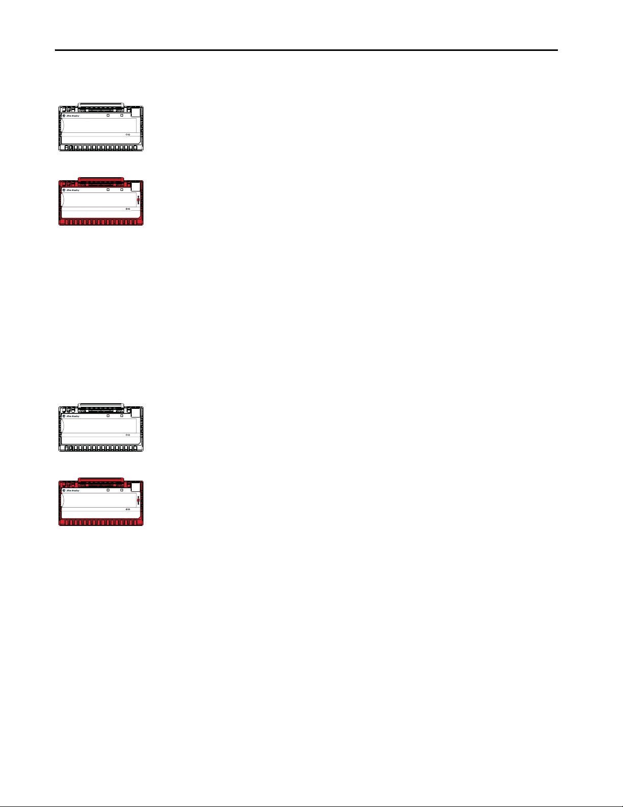
Chapter 2 Common Digital I/O Module Features
Safety Modules
Standard Modules
Safety Modules
Standard Modules
Input Module Compatibility
STATUS
POWER
FLEX 5000TM I/O
DIGITAL 16 INPUT 24 VDC
5094-IB16
0 1 2 3 4 5 6 7 8 9 10 11 12 13 14 15
FLEX 5000TM I/O
SAFETY DIGITAL 16 INPUT 24 VDC
5094-IB16S
0 1 2 3 4 5 6 7 8 9 10 11 12 13 14 15
1
1
TB3
STATUS
POWER
5
5
TB3I
FLEX 5000 digital input modules interface to sensing devices and detect whether
they are On or Off.
FLEX 5000 digital input modules convert DC On/Off signals from user devices
to appropriate logic level for use within the processor. Typical input devices
include the following:
•Proximity switches
• Limit switches
• Selector switches
• Float switches
• Push button switches
When you design systems with FLEX 5000 digital input modules, consider these
factors:
• Voltage necessary for your application
• Current leakage
• Whether you need a solid-state device
• Whether your application uses sinking or sourcing wiring
Output Module Capability
5094-IB16
0 1 2 3 4 5 6 7 8 9 10 11 12 13 14 15
5094-IB16S
0 1 2 3 4 5 6 7 8 9 10 11 12 13 14 15
Producer/Consumer Communication
FLEX 5000TM I/O
DIGITAL 16 INPUT 24 VDC
FLEX 5000TM I/O
SAFETY DIGITAL 16 INPUT 24 VDC
FLEX 5000 digital output modules can be used to drive various output devices.
Typical output devices compatible with FLEX 5000 digital output modules
include these items:
STATUS
POWER
1
1
TB3
• Motor starters
• Solenoids
•Indicators
STATUS
POWER
5
5
TB3I
Follow these guidelines when designing a system:
• Make sure that the FLEX 5000 digital output modules can supply the
necessary surge and continuous current for proper operation.
• Make sure that the surge and continuous current are not exceeded.
Damage to the module could result.
When you size output loads, refer to the documentation supplied with the output
device for the surge and continuous current necessary to operate the device.
FLEX 5000 digital I/O modules use the Producer/Consumer communication
model to produce data without a controller polling them first. The modules
produce the data and controllers consume it. That is, the owner-controller and
controllers with a Listen Only connection to the module can consume it.
46 Rockwell Automation Publication 5094-UM001C-EN-P - April 2019
When an input module produces data, the controllers can consume the data
simultaneously. Simultaneous data consumption mitigates the need for one
controller to send the data to other controllers.
Page 47

Common Digital I/O Module Features Chapter 2
STATUS
POWER
SAFETY DIGITAL 16 INPUT 24 VDC
5094-IB16S
5
5
TB3I
FLEX 5000TM I/O
0 1 2 3 4 5 6 7 8 9 10 11 12 13 14 15
STATUS
POWER
DIGITAL 16 INPUT 24 VDC
5094-IB16
1
1
TB3
FLEX 5000TM I/O
0 1 2 3 4 5 6 7 8 9 10 11 12 13 14 15
Safety Modules
Standard Modules
Module Data Quality Reporting
The FLEX 5000 digital I/O modules indicate the quality of point data that is
returned to the owner-controller. Data quality represents accuracy. Levels of data
quality are reported via module input tags.
The following inputs indicate the level of data quality.
IMPORTANT Once the condition that causes the Fault or Uncertain tag to change to 1 is
removed, the tag automatically resets to 0. The Logix Designer application
controls the tags. You cannot change the status of the tags.
Keep in mind that in some system configurations, the tag is not reset
immediately after the condition is removed. The tag typically resets after a
small delay.
• I.Ptxx.Fault - This tag indicates that the reported point data is inaccurate
and cannot be trusted for use in your application. Do not use the reported
channel data for control.
If the tag is set to 1, you cannot trust the data reported. You must
troubleshoot the module to correct the cause of the inaccuracy.
Example causes of inaccurate data include the following:
– Field Power Loss condition (output modules)
– No Load condition (output modules)
– Short Circuit condition (output modules)
TIP We recommend that you troubleshoot the module for the typical
causes first.
• I.Ptxx.Uncertain - This tag indicates that the reported point data can be
inaccurate but the degree of inaccuracy is unknown. We recommend that
you do not use the reported channel data for control.
If the tag is set to 1, you know that the data can be inaccurate. You must
troubleshoot the module to discover what degree of inaccuracy exists.
Example causes of uncertain data include the following:
– Module is operating outside its designed operating range
– Data is under manual or override control
TIP We strongly recommend that you monitor the tags in your program to
make sure that the application is operating as expected with accurate
channel input data.
Rockwell Automation Publication 5094-UM001C-EN-P - April 2019 47
Page 48

Chapter 2 Common Digital I/O Module Features
Safety Modules
Standard Modules
Safety Modules
Standard Modules
Safety Modules
Standard Modules
Software Configurable
STATUS
POWER
FLEX 5000TM I/O
DIGITAL 16 INPUT 24 VDC
5094-IB16
0 1 2 3 4 5 6 7 8 9 10 11 12 13 14 15
FLEX 5000TM I/O
SAFETY DIGITAL 16 INPUT 24 VDC
5094-IB16S
0 1 2 3 4 5 6 7 8 9 10 11 12 13 14 15
1
1
TB3
STATUS
POWER
5
5
TB3I
Fault and Status Reporting
STATUS
POWER
FLEX 5000TM I/O
DIGITAL 16 INPUT 24 VDC
5094-IB16
0 1 2 3 4 5 6 7 8 9 10 11 12 13 14 15
1
1
TB3
You use the Logix Designer application to configure the module, monitor system
operation, and troubleshoot issues. You can also use the Logix Designer
application to retrieve the following information from any module in the system:
• Serial number
• Firmware revision information
• Product code
•Vendor
• Error and fault information
• Diagnostic information
By minimizing the need for tasks, such as setting hardware switches and jumpers,
the software makes module configuration easier and more reliable.
The FLEX 5000 digital I/O modules report fault and status data along with
point data. Fault and status data is reported in the following ways:
• Logix Designer application
•Module status indicators
IMPORTANT Do not use the module status indicators or I/O status indicators on
FLEX 5000 I/O safety modules for safety operations.
5094-IB16S
0 1 2 3 4 5 6 7 8 9 10 11 12 13 14 15
Module Firmware
5094-IB16
0 1 2 3 4 5 6 7 8 9 10 11 12 13 14 15
5094-IB16S
0 1 2 3 4 5 6 7 8 9 10 11 12 13 14 15
FLEX 5000TM I/O
SAFETY DIGITAL 16 INPUT 24 VDC
FLEX 5000TM I/O
DIGITAL 16 INPUT 24 VDC
FLEX 5000TM I/O
SAFETY DIGITAL 16 INPUT 24 VDC
STATUS
POWER
For more information on fault reporting, see the individual module feature
5
5
TB3I
chapters and Appendix A
, Troubleshoot Your Module on page 123.
The FLEX 5000 digital I/O modules are manufactured with module firmware
installed. If updated module firmware revisions are available in the future, you
can update the firmware.
STATUS
POWER
1
1
TB3
Updated firmware revisions are made available for various reasons, for example,
to correct an anomaly that existed in previous module firmware revisions.
Firmware information for I/O devices is available at the Rockwell Automation
STATUS
POWER
Product Compatibility and Download Center (PCDC). The PCDC is available
at: https://compatibility.rockwellautomation.com/Pages/home.aspx
5
5
TB3I
At the PCDC, you can use the module catalog number to check for firmware
updates. If the catalog number is not available, then no updates exist.
Verify that the firmware revision of the FLEX 5000 I/O modules that you use is
correct before commissioning the system.
48 Rockwell Automation Publication 5094-UM001C-EN-P - April 2019
IMPORTANT Only download firmware and access product release notes from the
Rockwell Automation PCDC.
Do not download firmware from non-Rockwell Automation sites.
Page 49

Common Digital I/O Module Features Chapter 2
STATUS
POWER
SAFETY DIGITAL 16 INPUT 24 VDC
5094-IB16S
5
5
TB3I
FLEX 5000TM I/O
0 1 2 3 4 5 6 7 8 9 10 11 12 13 14 15
STATUS
POWER
DIGITAL 16 INPUT 24 VDC
5094-IB16
1
1
TB3
FLEX 5000TM I/O
0 1 2 3 4 5 6 7 8 9 10 11 12 13 14 15
Safety Modules
Standard Modules
Module Inhibiting
Module inhibiting lets you indefinitely suspend a connection, including Listen
Only connections, between an owner-controller and a digital I/O module
without removing the module from the configuration. This process lets you
temporarily disable a module, such as to perform maintenance.
IMPORTANT You cannot inhibit a connection when the controller is safety-locked or a
safety signature exists for the controller.
You can use module inhibiting in the following ways:
• You write a configuration for an I/O module but inhibit the module to
help prevent it from communicating with the owner-controller. The owner
does not establish a connection and the configuration is not sent to the
module until the connection is uninhibited.
• In your application, a controller already owns a module, has downloaded
the configuration to the module, and is exchanging data over the
connection between the devices.
In this case, you can inhibit the module and the connection to the module
does not exist.
IMPORTANT Whenever you inhibit an output module that is ProgMode enabled,
it enters Program mode, and all outputs change to the state
configured for Program mode.
For example, if an output module is configured so that the state of
the outputs transition to zero during Program mode, whenever that
module is inhibited, outputs transition to zero.
You can use module inhibiting in these instances:
• You want to update a digital I/O module, for example, update the module
firmware revision. Use the following procedure.
a. Inhibit the module.
b. Perform the update.
c. Uninhibit the module.
• You use a program that includes a module that you do not physically
possess yet. You do not want the controller to look for a module that does
not yet exist. In this case, you can inhibit the module in your program until
it physically resides in the proper slot.
To see where to inhibit a FLEX 5000 digital I/O module, see
page 120.
Rockwell Automation Publication 5094-UM001C-EN-P - April 2019 49
Page 50
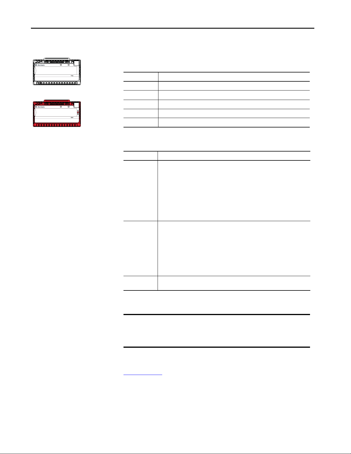
Chapter 2 Common Digital I/O Module Features
Safety Modules
Standard Modules
Electronic Keying
STATUS
POWER
FLEX 5000TM I/O
DIGITAL 16 INPUT 24 VDC
5094-IB16
0 1 2 3 4 5 6 7 8 9 10 11 12 13 14 15
FLEX 5000TM I/O
SAFETY DIGITAL 16 INPUT 24 VDC
5094-IB16S
0 1 2 3 4 5 6 7 8 9 10 11 12 13 14 15
1
1
TB3
STATUS
POWER
5
5
TB3I
Electronic Keying reduces the possibility that you use the wrong device in a
control system. It compares the device that is defined in your project to the
installed device. If keying fails, a fault occurs. These attributes are compared.
Attribute Description
Vendor The device manufacturer.
Device Type The general type of the product, for example, digital I/O module.
Product Code The specific type of the product. The Product Code maps to a catalog number.
Major Revision A number that represents the functional capabilities of a device.
Minor Revision A number that represents behavior changes in the device.
The following Electronic Keying options are available.
Keying Option Description
Compatible
Module
Disable Keying Indicates that the keying attributes are not considered when attempting to communicate with
Exact Match Indicates that all keying attributes must match to establish communication. If any attribute
Lets the installed device accept the key of the device that is defined in the project when the
installed device can emulate the defined device. With Compatible Module, you can typically
replace a device with another device that has the following characteristics:
• Same catalog number
• Same or higher Major Revision
• Minor Revision as follows:
– If the Major Revision is the same, the Minor Revision must be the same or higher.
– If the Major Revision is higher, the Minor Revision can be any number.
• Non-XT and XT version as follows:
– You can use an XT version of the module in place of a non-XT module.
–You cannot use a non-XT version of the module in place of an XT module.
a device. With Disable Keying, communication can occur with a device other than the type
specified in the project.
IMPORTANT: This option is not available for Safety applications.
ATT EN TI ON : Be extremely cautious when using Disable Keying; if used incorrectly, this option
can lead to personal injur y or death, property damage, or economic loss.
We strongly recommend that you do not use Disable Keying.
If you use Disable Keying, you must take full responsibility for understanding whether the
device being used can fulfill the functional requirements of the application.
does not match precisely, communication with the device does not occur.
50 Rockwell Automation Publication 5094-UM001C-EN-P - April 2019
Carefully consider the implications of each keying option when selecting one.
IMPORTANT
Changing Electronic Keying parameters online interrupts connections to the device
and any devices that are connected through the device. Connections from other
controllers can also be broken.
If an I/O connection to a device is interrupted, the result can be a loss of data.
For more detailed information on Electronic Keying, see Electronic Keying in
Logix5000 Control Systems Application Technique, publication
LOGIX-AT001
.
Page 51

Common Digital I/O Module Features Chapter 2
STATUS
POWER
SAFETY DIGITAL 16 INPUT 24 VDC
5094-IB16S
5
5
TB3I
FLEX 5000TM I/O
0 1 2 3 4 5 6 7 8 9 10 11 12 13 14 15
STATUS
POWER
DIGITAL 16 INPUT 24 VDC
5094-IB16
1
1
TB3
FLEX 5000TM I/O
0 1 2 3 4 5 6 7 8 9 10 11 12 13 14 15
Safety Modules
Standard Modules
Module Firmware
The FLEX 5000 digital I/O modules are manufactured with module firmware
installed. If updated module firmware revisions are available in the future, you
can update the firmware.
Updated firmware revisions are made available for various reasons, for example,
to correct an anomaly that existed in previous module firmware revisions.
Firmware information for I/O devices is available at the Rockwell Automation
Product Compatibility and Download Center (PCDC). The PCDC is available
at:
https://compatibility.rockwellautomation.com/Pages/home.aspx
At the PCDC, you can use the module catalog number to check for firmware
updates. If the catalog number is not available, then no updates exist.
Verify that the firmware revision of the FLEX 5000 I/O modules that you use is
correct before commissioning the system.
IMPORTANT Only download firmware and access product release notes from the
Rockwell Automation PCDC.
Do not download firmware from non-Rockwell Automation sites.
Rockwell Automation Publication 5094-UM001C-EN-P - April 2019 51
Page 52

Chapter 2 Common Digital I/O Module Features
Notes:
52 Rockwell Automation Publication 5094-UM001C-EN-P - April 2019
Page 53

Chapter 3
STATUS
POWER
SAFETY DIGITAL 16 INPUT 24 VDC
5094-IB16S
5
5
TB3I
FLEX 5000TM I/O
0 1 2 3 4 5 6 7 8 9 10 11 12 13 14 15
STATUS
POWER
DIGITAL 16 INPUT 24 VDC
5094-IB16
1
1
TB3
FLEX 5000TM I/O
0 1 2 3 4 5 6 7 8 9 10 11 12 13 14 15
Safety Modules
Standard Modules
Input Module Features
Top ic Pag e
Data Transfer at RPI 53
Software Configurable Input Filters and Delays 54
Field Power Loss Detection 54
Fault and Status Reporting 55
This chapter describes features common to these FLEX 5000™ standard and
safety input modules:
• 16-point sinking standard input module, catalog number 5094-IB16
Data Transfer at RPI
• 16-point sinking standard input module for extreme environments,
catalog number 5094-IB16XT
• 16-point sinking safety input module, catalog number 5094-IB16S
• 16-point sinking safety input module for extreme environments,
catalog number 5094-IB16SXT
FLEX 5000 digital input modules always send data at the RPI, a user-defined rate
at which the module updates the information sent to its owner-controller.
To see where to set the RPI for standard modules, see page 26
modules, see page 114
.
, and for safety
Rockwell Automation Publication 5094-UM001C-EN-P - April 2019 53
Page 54

Chapter 3 Input Module Features
Safety Modules
Standard Modules
Filter delay time
Input signal
Filter result
Ptxx Input
timestamp
Ptxx Event
timestamp
Safety Modules
Standard Modules
Software Configurable Input Filters and Delays
STATUS
POWER
FLEX 5000TM I/O
DIGITAL 16 INPUT 24 VDC
5094-IB16
0 1 2 3 4 5 6 7 8 9 10 11 12 13 14 15
FLEX 5000TM I/O
SAFETY DIGITAL 16 INPUT 24 VDC
5094-IB16S
0 1 2 3 4 5 6 7 8 9 10 11 12 13 14 15
1
1
TB3
STATUS
POWER
5
5
TB3I
You can adjust On to Off and Off to On filter times through the Logix Designer
application for all FLEX 5000 digital input modules. These filters improve noise
immunity within a signal.
A larger filter value affects the length of delay times for signals from these
modules. The filter values are adjustable in the Points category of the Module
Properties window.
The input filter/delay values of the 5094-IB16/5094-IB16S and 5094-IB16XT/
5094-IB16SXT input modules range from 0 µs…50 ms.
To see where to set the input filter values for standard modules, see page 97
see where to set the input delay values for safety modules, see page 115
. To
.
Field Power Loss Detection
5094-IB16
0 1 2 3 4 5 6 7 8 9 10 11 12 13 14 15
5094-IB16S
0 1 2 3 4 5 6 7 8 9 10 11 12 13 14 15
FLEX 5000TM I/O
DIGITAL 16 INPUT 24 VDC
FLEX 5000TM I/O
SAFETY DIGITAL 16 INPUT 24 VDC
POWER
POWER
The Field Power Loss Detection feature monitors for the loss of power at an
input module point. When field power to the module is lost, a point-level fault is
sent to the controller to identify the exact point faulted.
STATUS
1
1
TB3
Field Power Loss Detection has a corresponding tag that can be examined in the
user program if a fault occurs. For information on modules, see Appendix B
,
Module Tag Definitions on page 137
STATUS
5
5
TB3I
To see where to enable or disable field power detection, see page 97.
54 Rockwell Automation Publication 5094-UM001C-EN-P - April 2019
Page 55

Input Module Features Chapter 3
STATUS
POWER
SAFETY DIGITAL 16 INPUT 24 VDC
5094-IB16S
5
5
TB3I
FLEX 5000TM I/O
0 1 2 3 4 5 6 7 8 9 10 11 12 13 14 15
STATUS
POWER
DIGITAL 16 INPUT 24 VDC
5094-IB16
1
1
TB3
FLEX 5000TM I/O
0 1 2 3 4 5 6 7 8 9 10 11 12 13 14 15
Safety Modules
Standard Modules
Fault and Status Reporting
The digital input modules multicast fault and status data with point data to the
owner and listening controllers. The data is returned via modules that you can
monitor in your Logix Designer application.
With some exceptions, the FLEX 5000 digital input modules provide the fault
and data status in a point-centric format. The tag names in the following table
that include Ptxx represent point-centric data. The xx represents the point
number.
For more information on fault reporting, see Appendix A, Troubleshoot Your
Module on page 123.
Table 9 - FLEX 5000 Digital Input Module - Fault and Data Status
Data Type Tag Name
Fau lt
Conne ctionFaul ted
Ptxx.Fault The point data quality is bad.
RunMode The module is in Run Mode.
DiagnosticActive Indicates if any diagnostics are active.
DiagnosticSequenceCount A counter that increments when a diagnostic condition occurs or
Status
Ptxx.Data The point input status is one or zero.
Ptxx.Uncertain The point data can be imperfect.
Uncertain
(1) Not all tag names apply to all FLEX 5000 digital input modules.
(2) This tag provides module-wide data and affects all points simultaneously.
(1)
(2)
Triggering Event That Sets the Tag
The owner-controller loses its connection to the module.
goes away. The counter is a rolling counter that skips 0 on rollovers.
(2)
The module is operating outside its designed operating range if
data is under manual or override control.
Rockwell Automation Publication 5094-UM001C-EN-P - April 2019 55
Page 56

Chapter 3 Input Module Features
Notes:
56 Rockwell Automation Publication 5094-UM001C-EN-P - April 2019
Page 57

Chapter 4
STATUS
POWER
SAFETY DIGITAL 16 INPUT 24 VDC
5094-IB16S
5
5
TB3I
FLEX 5000TM I/O
0 1 2 3 4 5 6 7 8 9 10 11 12 13 14 15
STATUS
POWER
DIGITAL 16 INPUT 24 VDC
5094-IB16
1
1
TB3
FLEX 5000TM I/O
0 1 2 3 4 5 6 7 8 9 10 11 12 13 14 15
Safety Modules
Standard Modules
Output Module Features
Top ic Pag e
Features Specific to All FLEX 5000 Output Modules 57
Features Specific to Only 5094-OB16 and 5094-OB16XT Modules 66
Feature Specific to Only 5094-OW8I and 5094-OW8IXT Modules 69
This chapter describes features common to these FLEX 5000™ standard and
safety output modules:
• 16-point standard DC output module, catalog number 5094-OB16
• 16-point standard DC output module for extreme environments,
catalog number 5094-OB16XT
Features Specific to All FLEX 5000 Output Modules
• 16-point safety DC output module, catalog number 5094-OB16S
• 16-point safety DC output module for extreme environments,
catalog number 5094-OB16SXT
• Standard relay output module, catalog number 5094-OW8I
• Standard relay output module for extreme environments,
catalog number 5094-OW8IXT
The following topics are specific to all FLEX 5000 output modules.
Output State Change Time
Ta b l e 1 0 lists the time that it takes for FLEX 5000 output module outputs to
change state after a command.
Table 10 - Time for a Module Output to Change States
Module Time
5094-OB16, 5094-OB16XT 100 μs
5094-OB16S, 5094-OB16SXT 4.5 ms
5094-OW8I, 5094-OW8IXT 10 ms
(1) The times that are listed in Tabl e 10 are from the time the module receives the message.
(1)
Rockwell Automation Publication 5094-UM001C-EN-P - April 2019 57
Page 58

Chapter 4 Output Module Features
Configurable Point-level Output State in Program Mode or Fault Mode
You can configure individual output points to specific states when the module is
in Program mode or Fault mode. The following output states are available:
•Off
•On
• Hold last state
To see where to configure the output states in Program mode or Fault mode, see
the following:
• 5094-OB16 and 5094-OB16XT modules - page 103
• 5094-OB16S and 5094-OB16SXT modules - page 117
• 5094-OW8I and 5094-OW8IXT modules - page 104
ATT EN TI ON : Overriding Output state from OFF to ON/HOLD during
Program or Communication Fault modes will interfere with the safety state
of the point.
Connection Fault Handling
You can configure FLEX 5000 output module behavior when a connection fault
occurs, that is, the connection between the owner-controller and the output
module breaks.
You m us t def in e t he fo ll ow in g :
• In standard and safety modules
– Immediate output behavior when the connection breaks
• In standard modules only
– Length of time that the output behaves as defined
– Output behavior if the connection remains broken when the length of
time that is defined previously expires
58 Rockwell Automation Publication 5094-UM001C-EN-P - April 2019
Page 59

Output Module Features Chapter 4
Output Behavior Immediately After a Connection Fault
ATT EN TI ON : Overriding Output state from OFF to ON/HOLD during
Program or Communication Fault modes will interfere with the safety state
of the point.
When the connection between an owner-controller and output module breaks,
the output can behave in the following ways, depending on how the Fault Mode
parameter is configured:
• Turn off - Default
• Transition to a specific, user-defined value
• Hold its last state
The output remains at that state value until the following occurs:
• The connection to the owner-controller is re-established.
• The output returns to normal operation, as defined in the module
configuration.
Output State Once Connection Is Re-established
Once the connection between the owner-controller and output module is reestablished, the output resumes normal operation.
To see where to configure the Connection Fault Handling parameters,
see the following:
• 5094-OB16 and 5094-OB16XT modules - page 103
• 5094-OB16S and 5094-OB16SXT modules - page 117
• 5094-OW8I and 5094-OW8IXT modules - page 104
Forcing
Use a force to override data that your logic either uses or produces.
• Test and debug your logic.
• Temporarily maintain normal system operations when an input device
has failed.
Use forces only as a temporary measure. They are not intended to be a permanent
part of your application.
Make sure that you understand the following before using forces.
Rockwell Automation Publication 5094-UM001C-EN-P - April 2019 59
Page 60

Chapter 4 Output Module Features
ATTENTION: Forcing can cause unexpected machine motion that could
injure personnel. Before you use a force, determine how the force affects
your machine or process and keep personnel away from the machine area.
• Enabling I/O or SFC forces causes your machine or process to go to another
state or phase.
• Removing forces can still leave forces in the enabled state.
• If forces are enabled and you install a force, the new force immediately
takes effect.
Enable Forces
For a force to take effect, you enable forces. You can only enable and disable forces
at the controller level.
• You can enable I/O forces and SFC forces separately or simultaneously.
• You cannot enable or disable forces for a specific module, tag collection, or
tag element.
Disable or Remove a Force
To stop the effect of a force and let your project execute as programmed, disable
or remove the force.
• You can disable or remove I/O and SFC forces simultaneously or
separately.
• When you remove a force on an alias tag, you also remove the force on the
base tag.
ATTENTION: Changes to forces can cause unexpected machine motion that
could injure personnel. Before you disable or remove forces, determine how
the change affects your machine or process and keep personnel away from
the machine area.
60 Rockwell Automation Publication 5094-UM001C-EN-P - April 2019
Page 61

Output Module Features Chapter 4
Forces ta b
Check Force Status
Before you use a force, determine the status of forces for the controller.
The Online toolbar shows the status of forces. It shows the status of I/O forces
and SFC forces separately.
To determine the status of Use any of the following
I/O forces • Online toolbar
• GSV instruction
SFC forces Online toolbar
Force s Tab Stat us M eans
Enabled • If the project contains any forces of this type, they are overriding your logic.
• If you add a force of this type, the new force immediately takes effect
Disabled Forces of this type are inactive. If the project contains any forces of this type, they are not
Installed At least one force of this type exists in the project.
None Installed No forces of this type exist in the project.
overriding your logic.
GSV Instruction
This example shows how to use a GSV instruction to get the status of forces.
For the purposes of this example, Force_Status is a DINT tag.
Rockwell Automation Publication 5094-UM001C-EN-P - April 2019 61
Page 62

Chapter 4 Output Module Features
Table 11 - GSV Instruction
To determine the following Examine this bit For this value
Forces are installed 0 1
No forces are installed 0 0
Forces are enabled 1 1
Forces are disabled 1 0
Data Echo
Data Echo automatically multicasts point data values that match the digital value
that was sent to the screw terminals of the module then.
A FLEX 5000 digital output module returns a value sent to it by the ownercontroller. The echoed value is either On or Off.
Fault and status data are also sent. This data is sent at the RPI.
Field Power Loss Detection
The Field Power Loss Detection feature monitors for the loss of power at an
output module point. When field power to the module is lost, a point-level fault
is sent to the controller to identify the exact point faulted.
Field Power Loss Detection has a corresponding tag that can be examined in the
user program if a fault occurs. For information on modules, see Appendix B
,
Module Tag Definitions on page 137
Fault and Status Reporting
The digital output modules multicast fault and status data with point data to the
owner and listening controllers. The data is returned via modules that you can
monitor in your Logix Designer application.
IMPORTANT For 5094-OB16 and 5094-OB16XT output modules only, an output must
remain in the On state for a minimum of 250 ms for an overload or short
circuit to be detected. However, if a short-circuit condition exists long term,
it is detected as long as the output is switching at a rate no faster than 1 ms.
For more information on fault reporting, see Appendix A, Troubleshoot Your
Module on page 123.
62 Rockwell Automation Publication 5094-UM001C-EN-P - April 2019
Page 63

Table 12 - FLEX 5000 Digital Output Module - Fault and Data Status
Data Type Tag Name
Conne ction Faul ted
Fau lt
Status
(1) Not all tag names apply to all FLEX 5000 tag.digital I/O modules.
(2) This tag provides module-wide data an affects all points simultaneously.
Ptxx.Fault The point data quality is bad.
Ptxx.NoLoad A no load condition exists on the point.
Ptxx.ShortCircuit A short-circuit condition exists on the point.
RunMode The module is in Run Mode.
DiagnosticActive Indicates if any diagnostics are active.
DiagnosticSequenceCount A counter that increments when a diagnostic condition occurs or
Ptxx.Data The point data is one or zero.
Ptxx.Uncertain The point data can be imperfect.
Uncertain
(1)
(2)
(2)
Triggering Event That Sets the Tag
The owner-controller loses its connection to the module.
goes away. The counter is a rolling counter that skips 0 on rollovers.
The module is operating outside its designed operating range if
data is under manual or override control.
Output Module Features Chapter 4
Features Specific to Only
Standard and Safety Solidstate Output Modules
The following features are specific to only the standard and safety solid-state
output modules, catalog numbers 5094-OB16, 5094-OB16XT, 5094-OB16S,
and 5094-OB16SXT.
No Load Detection
No Load Detection detects when a wire is disconnected from the output or a
missing load for each output point.
For standard modules, No Load Detection occurs only when the output point is
in the Off state. For safety modules, No Load Detection occurs when the output
points are in either state, Off or On.
For standard modules, the No Load Detection feature is disabled by default. You
must enable the feature in your Logix Designer application project. For safety
modules, the No Load Detection feature is always enabled; it is not configurable.
IMPORTANT These FLEX 5000 output modules are the only ones to support
No Load Detection:
• 5094-OB16
• 5094-OB16XT
• 5094-OB16S
• 5094-OB16SXT
The standard output modules support the following minimum load currents:
• No load detection current, max = 0.5 mA
Rockwell Automation Publication 5094-UM001C-EN-P - April 2019 63
Page 64

Chapter 4 Output Module Features
• On-state current per point, max = 1 mA
For safety output modules (5094-OB16S and 5094-OB16SXT), the guaranteed
load detection is 10 mA for both states, Off and On.
Recommended Loading Resistor - To limit the effects of leakage current through
solid-state outputs, you can connect a loading resistor in parallel with your load.
For 24V DC operation in standard modules, use a 5.6K ohms, 0.5 W resistor for
transistor operation. For 24V DC operation in safety modules, use a 2.4K ohms,
0.5 W resistor for transistor operation.
In the On state, the module must be connected to a load that draws a minimum
current equal to these values.
IMPORTANT An output must remain in the off state a minimum of 250 ms for an open
load to be detected.
The I.Ptxx.NoLoad tag indicates the presence of a no load condition when it is
set to 1.
You can monitor a module tag in your program that corresponds to the No Load
Detection to check for a fault. For more information on the tag, see Appendix B
Module Tag Definitions on page 137
.
Short-Circuit Protection
Short-Circuit Protection helps prevent damage to the output that can result
when more current is present at the output than it can handle.
For safety output modules (5094-OB16S and 5094-OB16SXT),
I.Ptxx.ShortCircuit tag is used for short to high or channel to channel shorts,
which do not incur over current.
There are ShortCircuitGround and Overload tags in Diagnostic assembly.
IMPORTANT These FLEX 5000 output modules are the only ones to support the Short-
Circuit Detection feature:
• 5094-OB16
• 5094-OB16XT
• 5094-OB16S
• 5094-OB16SXT
,
In standard modules, when a short-circuit condition is detected, the following
occurs:
• The output turns off.
• The I/O status indicator for the output becomes steady red.
64 Rockwell Automation Publication 5094-UM001C-EN-P - April 2019
Page 65

• The I.Ptxx.ShortCircuit tag is set to 1.
Output Module Features Chapter 4
For more information on how to use the modules, see Appendix B
Module Tag Definitions on page 137
.
,
In standard modules, when the short-circuit condition is removed, the following
occurs:
• The output restarts in its commanded state.
• The I/O status indicator for the output turns off.
• The I.Ptxx.ShortCircuit tag is reset to 0.
For safety modules, refer to the Safety Output Fault Reset
procedure on page 85.
For more information on the maximum current that you can apply
to an output, see the FLEX 5000 Modules Specifications Technical Data,
publication 5094-TD001
.
Thermal Shutoff
Thermal Shutoff helps prevent damage to the output that can result when an
output gets hotter than it can handle.
IMPORTANT These FLEX 5000 digital output modules are the only ones to support the
Thermal Shutoff feature:
• 5094-OB16
• 5094-OB16XT
• 5094-OB16S
• 5094-OB16SXT
This feature is directly related to Short-Circuit Protection feature. The
increased temperature at the output results from an excessive load at the output.
That is, a load with high current is applied to the output. The high current heats
the output beyond an acceptable temperature and the output turns off.
In the safety output modules (5094-OB16S, 509-OB16SXT), if overload or
short circuit to ground occurs, the point will turn off. This trigger by current
threshold is exceeded, regardless of temperature.
For standard modules, when conditions exist that cause Thermal Shutoff to turn
off the output, the following occurs:
• The output turns off.
• The I/O status indicator for the output becomes solid red.
• The I.Ptxx.ShortCircuit tag is set to 1.
For more information on how to use the modules, see Appendix B
Module Tag Definitions on page 137
Rockwell Automation Publication 5094-UM001C-EN-P - April 2019 65
.
,
Page 66

Chapter 4 Output Module Features
STATUS
POWER
DIGITAL 16 INPUT 24 VDC
5094-IB16
1
1
TB3
FLEX 5000TM I/O
0 1 2 3 4 5 6 7 8 9 10 11 12 13 14 15
Standard Modules
For standard modules, when the conditions that caused a Thermal Shutoff no
longer exist, the following occurs:
• The output restarts in its commanded state.
• The I/O status indicator for the output turns off.
• The I.Ptxx.ShortCircuit tag is reset to 0.
Features Specific to Only 5094-OB16 and 5094-OB16XT Modules
For safety modules, refer to the Safety Output Fault Reset
procedure on page 85.
The following topics are specific to only the 5094-OB16 and 5094-OB16XT modules.
Time-scheduled Output Control
You can schedule times for module outputs to turn On or Off. The time
schedules use units in nanoseconds.
IMPORTANT These FLEX 5000 standard output modules are the only ones to support the
Time-scheduled Output Control feature:
• 5094-OB16
• 5094-OB16XT
The timing of scheduled outputs for the 5094-OB16 and 5094-OB16XT
modules are as follows:
– ±100 µs accuracy
– 1 ns resolution
66 Rockwell Automation Publication 5094-UM001C-EN-P - April 2019
The module must be time synced or schedules are note applied.
Time-scheduled output control is used with the Motion Arm Output Cam
(MAOC) instruction. The MAOC instruction enables position-based output
control in these ways:
• Uses the position of any motion axis in a Logix 5000™ control system as the
position reference
• Updates the outputs based on the motion axis position at the motion
group coarse update rate, typically 1…32 ms.
The instruction can update standard digital output modules at the coarse update
rate. However, some high-speed applications require a higher degree of accuracy.
The scheduled output modules improve the accuracy of the MAOC instruction
by supporting the ability to schedule output On and Off times. All scheduling
configuration for the On and Off times of an output is completed through the
MAOC instruction. The instruction then updates values in the output s of the
module that define the scheduled output behavior.
Page 67
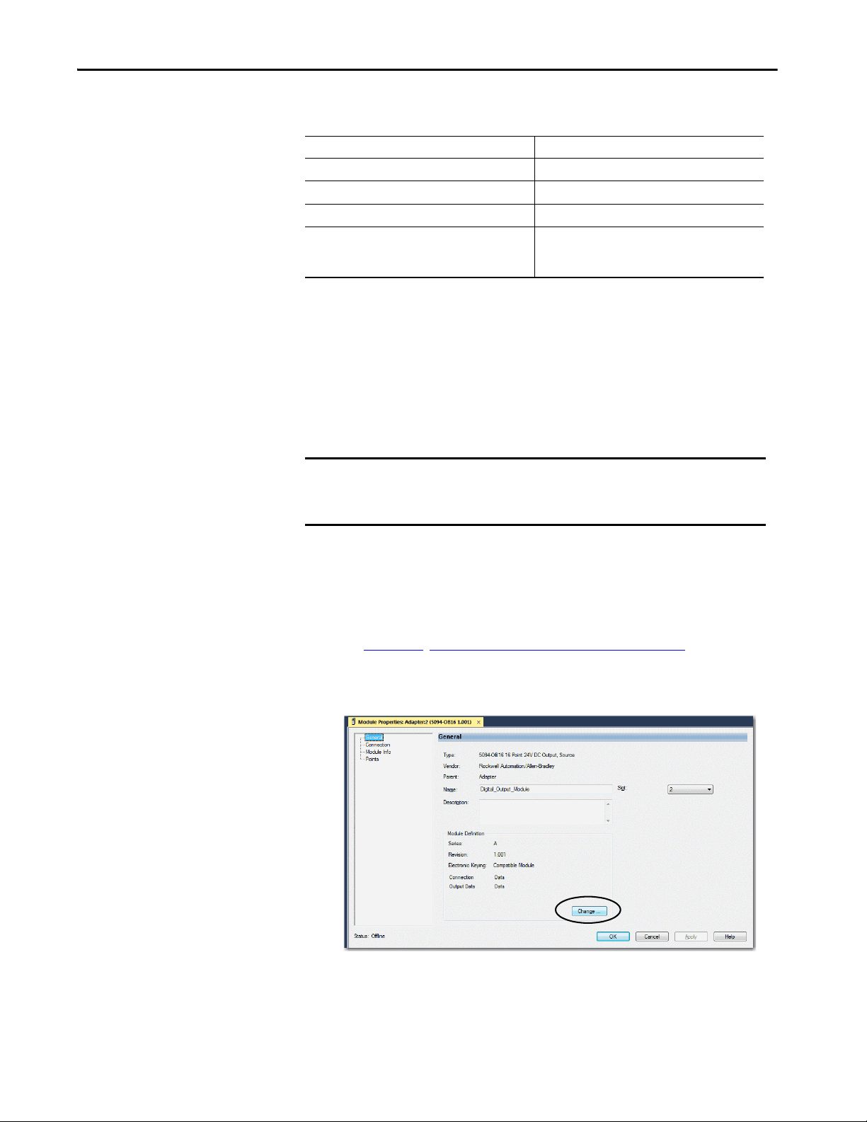
Output Module Features Chapter 4
Table 13 - FLEX 5000 Output Module Schedule Parameters
Feature 5094-OB16, 5094-OB16XT
Number of schedules 32
Output points available for scheduling 16 (points 0…15)
Remote operation N/A
Minimum schedule interval
(1) The MAOC limits the minimum schedule interval (minim um pulse width) to 1/16 of the coarse update period.
(1)
100 μs
For schedules output the MAOC instruction, you can use
50 μs.
Use a MAOC Instruction with a 5094-OB16 or 5094-OB16XT Standard Output Module
To use a MAOC instruction with schedule outputs on a 5094-OB16 or
5094-OB16XT output module, complete the following steps.
IMPORTANT Before you complete the steps, make sure that Time Synchronization is
enabled in the controller and, if applicable, the Ethernet module, to use
scheduled outputs.
1. If necessary, add a 5094-OB16 or 5094-OB16XT output module to your
Logix Designer application project.
For more information on how to add a 5094-OB16 or 5094-OB16XT
output module to a Logix Designer application and configure the module,
see Chapter 6
, Configure the Standard Module on page 87.
2. From the Module Properties dialog box, click Change to access the
Module Definition parameters.
Rockwell Automation Publication 5094-UM001C-EN-P - April 2019 67
Page 68

Chapter 4 Output Module Features
3. On the Module Definition dialog box, choose Scheduled Data for the
Output Data and click OK.
4. Click OK to close the Module Properties dialog box.
5. Add an MAOC instruction to your logic.
6. In the MAOC instruction, use the module output tag in the Output
operand, for example Adapter:1: O for the output module and
shown below.
The tag value displays as ??. This value is correct.
For more information on how to use an MAOC instruction in general, see
the following:
• Logix5000 Controllers Motion Instructions Reference Manual,
publication MOTION-RM002
• Position-based Output Control with the MAOC Instruction Application
Te ch ni qu e , p ub licati o n 1756-AT017
68 Rockwell Automation Publication 5094-UM001C-EN-P - April 2019
Page 69

Output Module Features Chapter 4
Standard Modules
Feature Specific to Only 5094-OW8I and 5094-OW8IXT Modules
STATUS
POWER
FLEX 5000TM I/O
DIGITAL 16 INPUT 24 VDC
5094-IB16
0 1 2 3 4 5 6 7 8 9 10 11 12 13 14 15
1
1
TB3
The following topic is specific to only the 5094-OW8I and 5094-OW8IXT
relay modules.
Isolated Output
These digital output modules provide point-to-point wiring isolation:
• 5094-OW8I
• 5094-OW8IXT
IMPORTANT Although some FLEX 5000 digital I/O modules do not provide wiring
isolation, all FLEX 5000 modules maintain internal electrical isolation
between the system-side and field-side power buses.
Rockwell Automation Publication 5094-UM001C-EN-P - April 2019 69
Page 70

Chapter 4 Output Module Features
Notes:
70 Rockwell Automation Publication 5094-UM001C-EN-P - April 2019
Page 71

Chapter 5
STATUS
POWER
SAFETY DIGITAL 16 INPUT 24 VDC
5094-IB16S
5
5
TB3I
FLEX 5000TM I/O
0 1 2 3 4 5 6 7 8 9 10 11 12 13 14 15
Safety Modules
Safety I/O Module Features
Top ic Pag e
Safety Input Module Features 71
Safety Output Module Features 79
Fault and Status Reporting 86
This chapter describes features that are specific to FLEX 5000™ I/O safety
modules.
Safety Input Module Features
This section describes features that are available on the FLEX 5000 I/O safety
input modules, that is, the 5094-IB16S and 5094-IB16SXT modules.
The 5094-IB16S and 5094-IB16SXT modules are 16-point safety sinking input
modules that use 16 safety inputs and 8 test outputs.
Safety Application Suitability Levels
Ta b l e 1 4 describes the safety application suitability levels for a 5094-IB16S and
5094-IB16SXT module.
Table 14 - Safety Application Suitability for 5094-IB16S and 5094-IB16SXT Modules
Suitability Level Conditions Notes
Applications that are rated up to, and including,
SIL CL3, PLc, Cat.2, as defined in IEC 61508,
IEC 61551, IEC 62061, and ISO 13849-1
Applications that are rated up to, and including,
SIL CL3, PLe, Cat.4, as defined in IEC 61508,
IEC 61551, IEC 62061, and ISO 13849-1
The modules uses single-channel mode
– Point mode is Safety Pulse Test or Safety
1. The modules use single-channel mode:
– Point mode is Safety Pulse Test or Safety
– Use shredded cable or cable trunk to separate channel
wiring to mitigate short-circuit faults.
2. The modules use dual-channel mode:
–Point mode is Safety
– Use shredded cable or cable trunk to separate channel
wiring to mitigate short-circuit faults.
3. The modules use dual-channel mode:
– Point mode is Safety Pulse Test only
Consider the following:
• The channel mode type, that is, single or dual, affects
Performance Level and Category. You can use the
modules in SIL CL3 applications regardless of channel
mode type.
• To achieve SIL CL3 single-channel, the sensor that is
used must be SIL CL3 single -channel as well.
• The requirement that Point mode be Safety Pulse Test
assumes that only the safety I/O module provides
diagnostics to a specific Suitability Level.
The larger safety system within which the safety I/O
module resides can provide the diagnostics necessary to
achieve the stated Suitability Level without the
requirement that Point mode be Safety Pulse Test.
To achieve the specific Safety Integrity Level, see
Appendix C, Application/Wiring Examples for Safety I/O
Modules on page 155
.
Rockwell Automation Publication 5094-UM001C-EN-P - April 2019 71
Page 72

Chapter 5 Safety I/O Module Features
Input Modules in CIP Safety Systems
The following apply to the safety inputs:
• You can connect safety devices, such as Emergency Stop Push Button, gate
switches, and safety light curtains.
• An external wiring short-circuit check is possible when inputs are wired in
combination with test outputs. The module must be wired in combination
with test outputs when this function is used.
• Independently adjustable on and off delays are available per channel.
• If you configure test outputs, you must choose a test source.
• Diagnostics. See Point Diagnostics
.
• Safety input points are configured as the following:
–Not Used
–Safety
– Safety Pulse Test
The following apply to the test outputs:
• Test outputs can be configured as the following:
–Not Used
–Power Supply
– Pulse Test
• Separate test outputs are provided for short-circuit detection of a safety
input (or inputs).
• Can supply 24V DC power to devices, such as safety sensors.
• Test output rating (TO) 200 mA @ 18…32V DC
72 Rockwell Automation Publication 5094-UM001C-EN-P - April 2019
Page 73

Safety I/O Module Features Chapter 5
0 1 2 3 4 5 6 7 8 9 10 11 12 13 14 15
+ +–
SA– 16 17 18 19 20 21 22 23 24 25 26 27 28 29 30 31 SA–
Common
TO_0 TO_1 TO_2 TO_3 TO_4 TO_5 TO_6 TO_7 TO_0 TO_1 TO_2 TO_3 TO_4 TO_5 TO_6 TO_7
SA + 32 33 34 35 36 37 38 39 40 41 42 43 44 45 46 47 SA+
Test Outputs
Inputs
Sensor
2-wire
Sensor
3-wire
Use Test Output with a Safety Input
A test output can be used in combination with a safety input for short circuit and
cross-channel fault detection.
Configure the test output as a pulse test source and associate it to a specific safety
input. The associated safety input must use a Point Mode = Safety Pulse Test.
These mappings are the only allowed and default digital-input-to-test-output
association mappings for Safety Pulse Test configuration. Only a test output that
is configured as Pulse Test can be used as test source.
Safety Input Maps to Test Output
0,8 0
1,9 1
2,10 2
3,11 3
4,12 4
5,13 5
6,14 6
7,15 7
Figure 7 - FLEX 5000 I/O Safety Input Module - Input Connected to Test Output
This diagram shows:
• A 2-wire sensor is connected to safety input 0, with test output 0
configured as Test Pulse/Power Supply.
• A 3-wire sensor is connected to safety input 15, with test output 7
configured as Power Supply.
Rockwell Automation Publication 5094-UM001C-EN-P - April 2019 73
Page 74

Chapter 5 Safety I/O Module Features
OUT
X
Y
On
Off
Figure 8 - 5094-IB16S and 5094-IB16SXT Test Pulse in a Cycle
On the 5094-IB16S and 5094-IB16SXT modules, the pulse width (X) is less
than 600 µs; the pulse period (Y) is less than 100 ms.
When the external input contact is closed, a test pulse is output from the test
output terminal to diagnose the field wiring and input circuitry. By using this
function, short circuits between inputs and 24V power and between input signal
lines can be detected. However, a short circuit between two input channels
cannot be detected if these two channels correspond to the same Test Output.
For example, Test Output 0 associates to Safety Input 0 and 8. If these two
channels short circuit, it cannot be detected.
Figure 9 - Short Circuit Between Input Signal Lines
74 Rockwell Automation Publication 5094-UM001C-EN-P - April 2019
Page 75

Safety I/O Module Features Chapter 5
24V
0V
Test O utpu t 0
Input Terminal 0
External Device
Fau lt D etec te d
ON
OFF
ON
OF F
ON
OFF
ON
OFF
24 V
0V
ON
OFF
Safe ty Input 0
Sta tus
Fault Detection
ON
OF F
ON
OFF
ON
OFF
Safet y I npu t 0
Stat us
Safety I nput 0
Data
Safe ty I nput 0
Data
Input Term in al 0
Normal Operation
External Device
Test Out put 0
Safety
I/O
Network
Data Sent
to the
Controller
Safety
I/O
Network
Data Sent
to the
Controller
Single-channel Mode
If an error is detected on the input channel, Safety Input Data and Safety Input
Status turn off.
For information about how using Single-channel mode with a 5094-IB16S or
5094-IB16SXT module affects the safety application suitability level, see
Table 14 on page 71
Figure 10 - Normal Operation and Fault Detection (Not to Scale)
.
Rockwell Automation Publication 5094-UM001C-EN-P - April 2019 75
Page 76

Chapter 5 Safety I/O Module Features
Safety Input Fault Reset
The I/O channel supports a module-level user-configurable ‘Latch Fault until
reset via output tag’ mode and recovers from these faults:
• Field Power Off Detection
• Safety Input Short Circuit
‘Latch Fault until reset via output tag’ mode is Enabled.
When Latch Fault... mode is Enabled, the I/O channel holds safety input fault
indications until it checks that the fault is removed. If the fault is removed, the
channel clears the fault status only upon detecting that the ResetFault in its
consume assembly channel sees a rising edge.
‘Latch Fault until reset via output tag’ mode is Disabled.
When Latch Fault... mode is Disabled (default), the I/O channel holds safety
input fault indications for 1 second until it checks if the fault is removed. If the
fault is removed, the channel clears the fault status only upon detecting the safety
input is low on the screw. If not, the channel continues to check if the fault is
removed.
76 Rockwell Automation Publication 5094-UM001C-EN-P - April 2019
Page 77

Safety I/O Module Features Chapter 5
On-delay
ON
OFFONOFF
Input Signal
Safe ty Input
Network Data
440 94
Safety Input Delay
This setting helps prevent rapid changes of input data due to contact bounce.
Off to On Delay
An input signal is treated as Logic 0 during the Off to On delay time after the
rising edge of the input contact.
The input turns on only if the input contact remains on after the Off to On delay
time has elapsed. This setting help prevent rapid changes of the input data due to
contact bounce.
You can delay the Off to On transition by the following times:
•0 ms
•1 ms
•2 ms
•5 ms
• 10 ms
• 20 ms
• 50 ms
Figure 11 - Off to On Delay
Rockwell Automation Publication 5094-UM001C-EN-P - April 2019 77
Page 78

Chapter 5 Safety I/O Module Features
Off-delay
ON
OFFONOFF
Input Signal
Safe ty Inp ut
Network Data
44 095
On to Off Delay
An input signal is treated as Logic 1 during the On to Off delay time after the
falling edge of the input contact.
The input turns off only if the input contact remains off after the On to Off delay
time has elapsed. This setting helps to prevent rapid changes of the input data due
to contact bounce.
You can delay the On to Off transition by the following times:
•0 ms
•1 ms
•2 ms
•5 ms
• 10 ms
• 20 ms
• 50 ms
Figure 12 - On to Off Delay
78 Rockwell Automation Publication 5094-UM001C-EN-P - April 2019
Page 79

Safety I/O Module Features Chapter 5
Safety Output Module Features
This section describes features that are available only on the FLEX 5000 I/O
safety output modules.
The 5094-OB16S and 5094-OB16SXT modules are safety sourcing output
module that use 16 digital safety outputs. You use the sourcing outputs in
Sourcing Output mode.
Safety Application Suitability Levels
Ta b l e 1 5 describes the safety application suitability levels for a 5094-OB16S or
5094-OB16SXT module.
Table 15 - Safety Application Suitability for 5094-OB16S and 5094-OB16SXT Module
Suitability Level Conditions Notes
Applications that are rated up to, and including,
SIL 3 as defined in IEC 61508, IEC 61511, and
IEC 62061, and PLc, cat. 2 as defined in
ISO 13849-1
Applications that are rated up to, and including,
SIL CL3, PLe, Cat.4, as defined in IEC 61508,
IEC 61551, IEC 62061, and ISO 13849-1
Use single-channel mode.
– Point mode is Safety Pulse Test or Safety.
1. The module uses single-channel mode.
– Point mode is Safety Pulse Test or Safety.
– Use IEC60947 certified Safety Contactor.
– Use shredded cable or cable trunk to separate channel wiring to
mitigate short-circuit faults.
2. The module uses dual-channel mode.
–Point mode is Safety.
– Use shredded cable or cable trunk to separate channel wiring to
mitigate short-circuit faults.
3. The module uses dual-channel
– Point mode is Safety Pulse Test.
mode.
Consider the following:
• The channel mode type, that is, single or
• The requirement that Point mode be
dual, affects Category. You can use the
modules in SIL 3, PLe applications
regardle ss of channel mode type.
Safety Pulse Test assumes that only the
safety I/O module provide diagnostics to a
specific Suitability Level.
The larger safety system within which the
safety I/O module resides can provide the
diagnostics necessary to achieve the
stated Suitability Level without the
requirement that Point mode be Safety
Pulse Test.
To achieve the specific Safety Integrity
Level, see Appendix C
Examples for Safety I/O Modules on
page 155.
, Application/Wiring
• Solid-state outputs
• Safety outputs can be pulse-tested to detect field wiring short circuits to
24V DC
• Supports field-power loss detection and configurable channel-level output
state in Fault and Program modes
Rockwell Automation Publication 5094-UM001C-EN-P - April 2019 79
Page 80

Chapter 5 Safety I/O Module Features
Output Module in CIP Safety Systems
The following apply to the safety outputs:
• You can connect safety devices, such as safety relays, safety contactors.
• An external wiring short-circuit check between channels or supply is
possible when the safety output is configured as Safety Pulse Test mode.
When the safety output is configured as Safety mode, external wiring
short-circuit check to supply is possible; check between channels is not
supported. The detection of external wiring fault is ≤ 300 msec.
• Diagnostics. See Status and Fault Information in Module Properties
Categories.
• Safety output points are configured as the following:
–Not Used
–Safety
– Safety Pulse Test
• Safety output point shall connect to a load that draws a minimum current
of 10 mA while in the “ON” state.
80 Rockwell Automation Publication 5094-UM001C-EN-P - April 2019
Page 81

Safety I/O Module Features Chapter 5
Safety and Safety Pulse Test Mode
The Safety Output can be configured to two types of point modes:
•Safety Mode
• Safety Pulse Test Mode
When the safety output is configured to Safety Mode, the safety output channel
continuously test the ability of the safety output switching elements ability to
turn off while maintaining the safety output at its nominal voltage with less than
1 Volt change. This small voltage variation during the pulse test is insignificant
for most of the connected device.
If an error is detected, the safety output data and individual safety output status
turn off.
On the 5094-OB16S and 5094-OB16SXT modules, the pulse width (X) is less
than 500 µs, and the pulse period (Y) is less than 200 ms.
When the safety output is configured to Safety Pulse Test Mode, the safety
output channel continuously test the ability of the safety output to remove power
from the output terminals of the module. The safety output turn off momentarily
during the pulse test duration.
If an error is detected, the safety output data and individual safety output status
turn off.
On the 5094-OB16S and 5094-OB16SXT modules, the pulse width (X) is less
than 500 µs, and the pulse period (Y) is less than 200 ms.
TIP To help prevent the test pulse from causing the connected device to
malfunction, pay careful attention to the input response time of the output
device.
Refer to 5094-OB16S and 5094-OB16SXT Module Wiring Diagrams
page 161
for more details about applying Safety Mode and Safety Pulse Test
on
Mode in your application.
Rockwell Automation Publication 5094-UM001C-EN-P - April 2019 81
Page 82

Chapter 5 Safety I/O Module Features
Normal Operation
Fault Detection
ON
OFF
ON
OFF
ON
OFF
ON
OFF
Safety Output 0
Status
Output 0
Safety Network Data
Sent to the Controller
Safety Output 0
Status
Output 0
Safety Network Data
Sent to the Controller
Error Detected
Single-channel Mode
When the output channel is in the On state and without any faults, the safety
outputs turned on. The status is normal. If a fault is detected on the output
channel, the safety output data and individual safety output status turn off.
For information about how using single-channel mode with a 5094-OB16S or
5094-OB16SXT module affects the safety application suitability level, see
Table 15 on page 79
Figure 13 - 5094-OB16S/5094-OB16SXT Single-channel Mode (Not to Scale)
.
82 Rockwell Automation Publication 5094-UM001C-EN-P - April 2019
Page 83

Safety I/O Module Features Chapter 5
Normal Operation
Fault Detection
ON
OFF
ON
OFF
ON
OFF
Safety Outputs 0
and 1 Status
Output 0
Safety Network Data
Sent to the Controller
Safety Outputs 0
and 1 Status
Output 1
Safety Network Data
Sent to the Controller
Error Detecte d
ON
OFF
ON
OFF
ON
OFF
Output 0
Output 1
Dual-channel Mode
When dual-channel mode is used, output channels function as connection pairs.
Connection pairs are as follows:
•Channels 0 and 1
•Channels 2 and 3
•Channels 4 and 5
•Channels 6 and 7
•Channels 8 and 9
• Channels 10 and 11
• Channels 12 and 13
• Channels 14 and 15
When both output channels in a connection pair are in the On state and without
any faults, the safety outputs are turned on.
For information about how using dual-channel mode with a 5094-OB16S or
5094-OB16SXT module affects the safety application suitability level, see
Table 15 on page 79
.
Figure 14 - 5094-OB16S Dual-channel Mode (Not to Scale)
Rockwell Automation Publication 5094-UM001C-EN-P - April 2019 83
Page 84

Chapter 5 Safety I/O Module Features
t1 = Surge time, maximum 150 msec
t2 = ON time
t3 - t2 = OFF time, 2 seconds
Surge Current per channel = 1.8 Amperes
IMPORTANT: The module current rating cannot exceed 10 Amperes at any time.
Current per channel
(Ampere)
Surge current
Rated current
t1 t2 t3 Time (sec)
Surge Capability of Safety Output
The safety output supports temporary surge of current when transitioning from
OFF to ON.
Figure 15 - Surge Capability of 5094-OB16S and 5094-OB16SXT
84 Rockwell Automation Publication 5094-UM001C-EN-P - April 2019
Page 85

Safety I/O Module Features Chapter 5
Safety Output Fault Reset
The I/O channel supports a module-level user-configurable ‘Latch Fault until
reset via output tag’ mode and recovers from only these faults:
• Field Power Off Detection
• Safety Output ShortCircuitGround
• Safety Output Overload
‘Latch Fault until reset via output tag’ mode is Enabled.
When Latch Fault... mode is Enabled, the I/O channel holds safety output fault
indications until it checks that the fault is removed. If the fault is removed, the
channel clears the fault status only upon detecting that the ResetFault in its
consume assembly channel sees a rising edge.
‘Latch Fault until reset via output tag’ mode is Disabled.
When Latch Fault... mode is Disabled (default), the I/O channel holds safety
output fault indications for 1 second until it checks if the fault is removed. If the
fault is removed, the channel clears the fault status only upon detecting the
consume data bit is low. If not, the channel continues to check if the fault is
removed.
After the channel clears the fault, the I/O indicator (red) turns off. The output
data can now be controlled.
IMPORTANT If the module outputs experience persistent high faults, consider cycling
power to the module to clear the error.
Rockwell Automation Publication 5094-UM001C-EN-P - April 2019 85
Page 86

Chapter 5 Safety I/O Module Features
Fault and Status Reporting
The FLEX 5000 I/O safety modules produce fault and status data with channel
data to the owner and listening controllers. The data is returned via module tags
that you can monitor in your Logix Designer application.
For more information on how to use module tags to monitor fault and status
reporting, see the following:
• 5094-IB16S and 5094-IB16SXT modules - Table 32 on page 147
• 5094-OB16S and 5094-OB16SXT modules - Table 34 on page 148
• Appendix A, Troubleshoot Your Module on page 123.
86 Rockwell Automation Publication 5094-UM001C-EN-P - April 2019
Page 87

Configure the Standard Module
STATUS
POWER
DIGITAL 16 INPUT 24 VDC
5094-IB16
1
1
TB3
FLEX 5000TM I/O
0 1 2 3 4 5 6 7 8 9 10 11 12 13 14 15
Standard Modules
Top ic Pag e
Before You Begin 88
Create a New Module 88
Edit the Module Configuration Common Categories 93
Edit 5094-IB16 Module Configuration Categories 97
Edit 5094-OB16 Module Configuration Categories 103
Edit 5094-OW8I Module Configuration Categories 104
View the Module Tags 105
Chapter 6
This chapter describes how to configure your FLEX 5000™ digital I/O modules
in a Logix Designer application project. You can use the default module
configuration or edit the module configuration.
IMPORTANT Consider the following:
• You must use the Studio 5000 Logix Designer® application, version 31 or
later, to configure the FLEX 5000 I/O modules. Version 31 or later is slightly
different from previous programming software versions. For example,
in some cases, instead of tabs across the top of the Module Properties
dialog box, the application uses categories on the left side of the
dialog box.
• This chapter does not explain the user-configurable module features that
you can edit on different screens in your Logix Designer application project.
For detailed information about module features, see the following:
- Chapter 2
, Common Digital I/O Module Features on page 45
- Chapter 3, Input Module Features on page 53
- Chapter 4, Output Module Features on page 57
Rockwell Automation Publication 5094-UM001C-EN-P - April 2019 87
Page 88

Chapter 6 Configure the Standard Module
Before You Begin
Create a New Module
You must complete the following tasks before you can configure the module:
1. Create a Logix Designer application project.
2. Add a FLEX 5000 EtherNet/IP adapter to the project.
For more information on how to add a FLEX 5000 EtherNet/IP adapter
to a Logix Designer application project, see the EtherNet/IP
Communication Modules in 5000 Series Systems User Manual,
publication ENET-UM004
After you create a Logix Designer application project and add a FLEX 5000
EtherNet/IP adapter to the project, you can use the following methods to add
modules to the project.
• Discover Modules
• New Module
.
88 Rockwell Automation Publication 5094-UM001C-EN-P - April 2019
Page 89

Configure the Standard Module Chapter 6
Discover Modules
To use the Discover Modules method with FLEX 5000 I/O modules, complete
these steps.
1. Go online with your Logix Designer application.
The project must include a FLEX 5000 EtherNet/IP adapter.
2. Right-click the FLEX 5000 EtherNet/IP adapter and choose Discover
Modules.
The Logix Designer application automatically detects available modules
that are connected to the backplane.
3. At the Select Module Type window, click Create to add the discovered
module to your project.
Rockwell Automation Publication 5094-UM001C-EN-P - April 2019 89
Page 90

Chapter 6 Configure the Standard Module
4. At the New Module window, configure the module properties and
click OK.
5. At the warning dialog box, make sure that Inhibit module connection is
selected and click Yes.
6. Close the Select Module Type dialog box.
To add additional I/O modules with this method, complete one of the following:
• If you cleared the Close on Create check box when you created the first
I/O module, repeat steps 3
…6.
• If you did not clear the Close on Create checkbox when you created the
first I/O module, repeat steps 2
…6.
90 Rockwell Automation Publication 5094-UM001C-EN-P - April 2019
Page 91

Configure the Standard Module Chapter 6
New Module
To use the New Module method with FLEX 5000 I/O modules, complete these
steps.
TIP This example shows how to add an I/O module when the Logix Designer
application project is offline.
You can add new modules when the project is online, if desired. In this case,
the steps are similar to the steps described in Discover Modules
One exception is that, in step 1, you choose New Module instead of Discover
Modules.
1. Right-click the FLEX 5000 EtherNet/IP adapter and choose
New Module.
on page 89.
Rockwell Automation Publication 5094-UM001C-EN-P - April 2019 91
Page 92

Chapter 6 Configure the Standard Module
2. Select the module and click Create.
The New Module dialog box appears with a list of categories on the left
side. The number and type of categories varies by module type.
3. You can click OK to use the default configuration as shown or edit the
module configuration. The rest of this chapter describes how to edit
module configuration categories.
To add additional remote I/O modules with this method, complete one of
the following:
• If you cleared the Close on Create checkbox when you created the first I/O
module, repeat steps 2
…3.
• If you did not clear the Close on Create checkbox when you created the
first I/O module, repeat steps 1
92 Rockwell Automation Publication 5094-UM001C-EN-P - April 2019
…3.
Page 93

Configure the Standard Module Chapter 6
Edit the Module Configuration Common Categories
You click the category names in the New Module dialog box to view and change
the configuration parameters.
IMPORTANT This chapter shows how to edit configuration when you add the module to
the Logix Designer application project.
If you access the module configuration after it is added to the project, the
dialog box is named Module Properties. The same categories are displayed
as the categories displayed on the New Module dialog box.
Some new module configuration categories apply to all FLEX 5000 digital I/O
modules. Some categories are specific to the module type.
For example purposes, the figures in this section are from a 5094-IB16 module.
The following categories apply to all FLEX 5000 digital I/O modules and are
described in this section.
• General Category
• Connection Category
• Module Info Category
General Category
The General category appears first when you create a module. The parameters in
this category are the same for all FLEX 5000 digital I/O modules.
You use this category to complete the following tasks:
• Name the module.
• Assign a slot number. (required)
• Describe the module.
• Access the Module Definition.
Rockwell Automation Publication 5094-UM001C-EN-P - April 2019 93
Page 94

Chapter 6 Configure the Standard Module
Module Definition
Module Definition parameters are available on the General tab of the Module
Properties dialog box in the Logix Designer application project.
Ta b l e 1 6
describes the parameters on the Module Definition dialog box.
IMPORTANT The graphic is an example of a Module Definition dialog box. The same set of
fields and options are not available on all FLEX 5000 I/O modules.
Table 16 - Module Definition Parameters
Parameter Definition Available Choices
Series Module hardware series Module -specific
Revision Module firmware revi sion, including major and minor revision levels Module-specific
Electronic Keying Software method by which you reduce the possibility of using the wrong device in a control system.
For more information, see the following:
• View the Module Tags
• Electronic Keying in Logix5000 Control Systems Application Technique, publication LOGI X-AT0 01
Connection Determines the following for the module type you configure:
Input Data - Input modules only All available configurations, input data. This connection type creates all controller tags specific to the
Counters - Input modules only Determines the number of counters that are used for the module type. None
Output Data - Output modules
only
(1) The choices that are available vary by module type and catalog number.
(2) Controller and module establish communication without the controller sending any configuration or output data to the module. A full input data connection is established but depends on the
connection between the owner-controller and the module.
• Available configuration parameters
• Data type transferred between the module and the controller
• Which tags are generated when configuration is complete
module type being used.
All available configurations, output data. This connection type creates all controller tags specific to the
module type being used.
on page 105
Exact Match
Compatible Module
Disable Keying
Data
Data with Events
Listen Only Data
Listen Only Data with Events
Data
Timestamped Data
Packe d Data
4
8
Data
Scheduled Data
Packe d Data
(1)
(2)
(2)
94 Rockwell Automation Publication 5094-UM001C-EN-P - April 2019
Page 95

Configure the Standard Module Chapter 6
Connection Category
The Connection category lets you complete the following tasks:
• Set the RPI rate. For more information on the RPI, see Data Types
Available with FLEX 5000 Standard I/O Modules on page 27.
• Set the connection type to use on the EtherNet/IP network.
For more information on unicast and multicast connections, see the
EtherNet/IP Communication Modules in 5000 Series Systems User
Manual, publication ENET-UM004
• Inhibit the module. For more information on how to inhibit the module,
see Module Inhibiting
on page 49.
• Configure whether a connection failure while the controller is in Run
module causes a major or minor fault.
TIP The Module Fault area of the Connection category is useful during module
troubleshooting. For more information on the Module Fault area, see
page 131
.
.
Rockwell Automation Publication 5094-UM001C-EN-P - April 2019 95
Page 96

Chapter 6 Configure the Standard Module
Module Info Category
The Module Info category displays module and status information about the
module when the project is online. You can use this category to complete the
following:
• Determine the identity of the module.
• Access module diagnostics.
• Refresh the data on the screen.
• Reset the module.
96 Rockwell Automation Publication 5094-UM001C-EN-P - April 2019
Page 97

Configure the Standard Module Chapter 6
Edit 5094-IB16 Module Configuration Categories
In addition to the General, Connection, and Module Info categories, the
following categories are available when you configure a 5094-IB16 module:
• Counters Category
• Points Category
• Events Category
• Time Sync Category
IMPORTANT If you use the Listen Only Data or Listen Only Data with Events connection
type, the Points Category, Counters Category, and Events Category do not
appear.
Counters Category
The Counters category is available only if you choose a value for Counters in the
Module Definition dialog box.
The Counters category shows the configuration options available for each
counter. Based on your Input Filter Time selections, the Input Filter Time
Off→On and On→Off times change. You can also configure the counter Preset
value and enable Rollover at Preset.
IMPORTANT The total number of Counters subtracts from the available number of Points.
For example, if you configure a 5094-IB16 module to use four counters, the
first four terminals are not available to use as points.
The number of points available on the module in this case is 12. That is,
points 4…15.
Rockwell Automation Publication 5094-UM001C-EN-P - April 2019 97
Page 98

Chapter 6 Configure the Standard Module
Points Category
The Points category shows the available input filter time values for the
module points.
If you choose Timestamped Data for Input Data in the Module Definition dialog
box, the Points category expands.
98 Rockwell Automation Publication 5094-UM001C-EN-P - April 2019
Page 99

Configure the Standard Module Chapter 6
PTxx Category
The PTxx category shows the configuration options available when you use
Timestamping on a point.
IMPORTANT You must choose the Input Data option Timestamp Data on the Module
Definition dialog box to see this category in the Module Properties dialog
box.
Click each Ptxx to configure it as necessary for your application.
Rockwell Automation Publication 5094-UM001C-EN-P - April 2019 99
Page 100
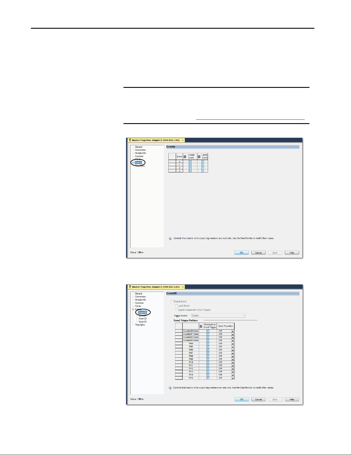
Chapter 6 Configure the Standard Module
Events Category
The Events category is available only if you choose Data with Events for
Connection in the Module Definition dialog box. Click the + sign next to the
Events category to expand it.
IMPORTANT You cannot configure events on the Module Properties dialog box. The
parameters that are displayed are read-only.
You must use the Event Output tags to configure an event. For more
information, see Configure an Event in the Event Output Tags
on page 101.
The Events subcategories show the configuration parameters for events.
100 Rockwell Automation Publication 5094-UM001C-EN-P - April 2019
 Loading...