

Page 1

Allen-Bradley
AdaptaScan
Bar Code
Application
Readers
(Cat. Nos. 2755-SN3, -SN5, and
-SN8)
Guide
Page 2

Important User Information
Because of the variety of uses for the products described in this
publication, those responsible for the application and use of this
control equipment must satisfy themselves that all necessary steps
have been taken to assure that each application and use meets all
performance and safety requirements, including any applicable laws,
regulations, codes and standards.
The illustrations, charts, sample programs and layout examples
shown in this guide are intended solely for purposes of example.
Since there are many variables and requirements associated with any
particular installation, Allen-Bradley does not assume responsibility
or liability (to include intellectual property liability) for actual use
based upon the examples shown in this publication.
Allen-Bradley publication SGI-1.1, Safety Guidelines for the
Application, Installation, and Maintenance of Solid-State Control
(available from your local Allen-Bradley office), describes some
important differences between solid-state equipment and
electromechanical devices that should be taken into consideration
when applying products such as those described in this publication.
Reproduction of the contents of this copyrighted publication, in
whole or in part, without written permission of Allen-Bradley
Company, Inc., is prohibited.
Throughout this manual we use notes to make you aware of safety
considerations:
ATTENTION: Identifies information about practices
or circumstances that can lead to personal injury or
!
death, property damage or economic loss.
Attention statements help you to:
• identify a hazard
• avoid the hazard
• recognize the consequences
Important: Identifies information that is critical for successful
application and understanding of the product.
PLC, PLC-5, and PHOTOSWITCH are registered trademarks of Allen-Bradley, Inc.
PanelView, PanelView 900, PanelBuilder, AdaptaScan, Data Highway Plus, SLC, SLC 500, SLC 5/03, and SLC 5/04 are
trademarks of Allen-Bradley Company, Inc.
APS is a trademark of Rockwell Software, Inc.
DeviceNet is a trademark of the Open DeviceNet Vendor Association
Windows is a trademark of Microsoft
Page 3

Preface
Contents of this Guide P–2. . . . . . . . . . . . . . . . . . . . . . . . . . . . . . . . .
Intended Audience P–4. . . . . . . . . . . . . . . . . . . . . . . . . . . . . . . . . . . .
Related Publications P–4. . . . . . . . . . . . . . . . . . . . . . . . . . . . . . . . . .
Technical Support Services P–4. . . . . . . . . . . . . . . . . . . . . . . . . . . . . .
Using the Auto-Load
Function
Chapter 1
Overview 1–1. . . . . . . . . . . . . . . . . . . . . . . . . . . . . . . . . . . . . . . . . .
Hardware Requirements 1–1. . . . . . . . . . . . . . . . . . . . . . . . . . . . . . . .
Software Requirements 1–1. . . . . . . . . . . . . . . . . . . . . . . . . . . . . . . .
Related Publications 1–1. . . . . . . . . . . . . . . . . . . . . . . . . . . . . . . . . .
Internal Power Source 1–2. . . . . . . . . . . . . . . . . . . . . . . . . . . . . . . . .
Connecting a Power Supply to the Reader 1–2. . . . . . . . . . . . . . . . . . .
Configuring the Reader 1–3. . . . . . . . . . . . . . . . . . . . . . . . . . . . . . . .
Create a New Project 1–3. . . . . . . . . . . . . . . . . . . . . . . . . . . . . . . .
Define a Bar Code Label 1–4. . . . . . . . . . . . . . . . . . . . . . . . . . . . .
Define the DeviceNet Address 1–5. . . . . . . . . . . . . . . . . . . . . . . . .
Configure the Scanner 1–5. . . . . . . . . . . . . . . . . . . . . . . . . . . . . . .
Configure the Decoder 1–6. . . . . . . . . . . . . . . . . . . . . . . . . . . . . . .
Configure the Discrete Input Module 1–6. . . . . . . . . . . . . . . . . . . . .
Configure the Match Table 1–7. . . . . . . . . . . . . . . . . . . . . . . . . . . .
Configure a Package 1–8. . . . . . . . . . . . . . . . . . . . . . . . . . . . . . . .
Configure the Auto-Load Trigger Source 1–9. . . . . . . . . . . . . . . . . .
Sending the Configuration to the Reader 1–10. . . . . . . . . . . . . . . . . . . .
Running the Application 1–10. . . . . . . . . . . . . . . . . . . . . . . . . . . . . . . .
Using ASCII Command Input
Chapter 2
Overview 2–1. . . . . . . . . . . . . . . . . . . . . . . . . . . . . . . . . . . . . . . . . .
Hardware Requirements 2–1. . . . . . . . . . . . . . . . . . . . . . . . . . . . . . . .
Software Requirements 2–1. . . . . . . . . . . . . . . . . . . . . . . . . . . . . . . .
Related Publications 2–1. . . . . . . . . . . . . . . . . . . . . . . . . . . . . . . . . .
Connecting a Computer to the Reader 2–2. . . . . . . . . . . . . . . . . . . . . .
Connecting a Power Supply to the Reader 2–2. . . . . . . . . . . . . . . . . . .
Configuring the Reader 2–3. . . . . . . . . . . . . . . . . . . . . . . . . . . . . . . .
Create a New Project 2–3. . . . . . . . . . . . . . . . . . . . . . . . . . . . . . . .
Define the Bar Code Label 2–4. . . . . . . . . . . . . . . . . . . . . . . . . . . .
Define the DeviceNet Address 2–5. . . . . . . . . . . . . . . . . . . . . . . . .
Configure the Scanner 2–5. . . . . . . . . . . . . . . . . . . . . . . . . . . . . . .
Configure the Decoder Trigger 2–6. . . . . . . . . . . . . . . . . . . . . . . . .
Configure the ASCII Commands 2–6. . . . . . . . . . . . . . . . . . . . . . . .
Configure the Serial Port 2–8. . . . . . . . . . . . . . . . . . . . . . . . . . . . .
Publication 2755-6.8
Page 4

Table of Contentstoc–ii
Create a Message 2–10. . . . . . . . . . . . . . . . . . . . . . . . . . . . . . . . . .
Define the Message Format 2–11. . . . . . . . . . . . . . . . . . . . . . . . . . .
Sending the Configuration to the Reader 2–12. . . . . . . . . . . . . . . . . . . .
Running the Application 2–12. . . . . . . . . . . . . . . . . . . . . . . . . . . . . . . .
Downloading Match Codes
from a Host Device
Chapter 3
Overview 3–1. . . . . . . . . . . . . . . . . . . . . . . . . . . . . . . . . . . . . . . . . .
Hardware Requirements 3–1. . . . . . . . . . . . . . . . . . . . . . . . . . . . . . . .
Software Requirements 3–1. . . . . . . . . . . . . . . . . . . . . . . . . . . . . . . .
Related Publications 3–1. . . . . . . . . . . . . . . . . . . . . . . . . . . . . . . . . .
Connecting a Computer to the Reader 3–2. . . . . . . . . . . . . . . . . . . . . .
Connecting a Power Supply to the Reader 3–2. . . . . . . . . . . . . . . . . . .
Configuring the Reader 3–3. . . . . . . . . . . . . . . . . . . . . . . . . . . . . . . .
Create a New Project 3–3. . . . . . . . . . . . . . . . . . . . . . . . . . . . . . . .
Define the Bar Code Label 3–4. . . . . . . . . . . . . . . . . . . . . . . . . . . .
Define the DeviceNet Address 3–5. . . . . . . . . . . . . . . . . . . . . . . . .
Configure the Scanner 3–5. . . . . . . . . . . . . . . . . . . . . . . . . . . . . . .
Configure the Decoder Trigger 3–6. . . . . . . . . . . . . . . . . . . . . . . . .
Configure the Serial Port 3–7. . . . . . . . . . . . . . . . . . . . . . . . . . . . .
Configuring a Match Entry and I/O Indicator LED 3–8. . . . . . . . . . . .
Sending the Configuration to the Reader 3–9. . . . . . . . . . . . . . . . . . . .
Finding Match Table Instances 3–10. . . . . . . . . . . . . . . . . . . . . . . . . . .
Connecting the Computer to the RS-232 Port 3–10. . . . . . . . . . . . . . . . .
Downloading Match Codes 3–11. . . . . . . . . . . . . . . . . . . . . . . . . . . . . .
Convert the Bar Code String to Hex 3–11. . . . . . . . . . . . . . . . . . . . . .
Place the String in the Data Packet 3–11. . . . . . . . . . . . . . . . . . . . . .
Send Data to the Reader 3–12. . . . . . . . . . . . . . . . . . . . . . . . . . . . .
Response Codes 3–14. . . . . . . . . . . . . . . . . . . . . . . . . . . . . . . . . . .
Downloading Other Host Commands 3–15. . . . . . . . . . . . . . . . . . . . . . .
Downloading Match Codes
via DH485 Protocol with an
SLC 5/03 or SLC 5/04
Controller
Publication 2755-6.8
Chapter 4
Overview 4–1. . . . . . . . . . . . . . . . . . . . . . . . . . . . . . . . . . . . . . . . . .
Hardware Requirements 4–1. . . . . . . . . . . . . . . . . . . . . . . . . . . . . . . .
Software Requirements 4–1. . . . . . . . . . . . . . . . . . . . . . . . . . . . . . . .
Related Publications 4–2. . . . . . . . . . . . . . . . . . . . . . . . . . . . . . . . . .
Connecting a Power Supply to the Reader 4–2. . . . . . . . . . . . . . . . . . .
Connecting to the DH-485 Network 4–2. . . . . . . . . . . . . . . . . . . . . . . .
Connecting Readers to SLC 5/03 Controller 4–3. . . . . . . . . . . . . . . .
Connecting Readers to SLC 5/04 Controller – 2 AIC Modules 4–4. . .
Connecting Readers to SLC 5/04 Controller – 1 AIC Module 4–5. . . .
Configuring Bar Code Reader 1 4–6. . . . . . . . . . . . . . . . . . . . . . . . . .
Create a New Project 4–6. . . . . . . . . . . . . . . . . . . . . . . . . . . . . . . .
Define the Bar Code Label 4–7. . . . . . . . . . . . . . . . . . . . . . . . . . . .
Define the DeviceNet Address 4–8. . . . . . . . . . . . . . . . . . . . . . . . .
Configure the Scanner 4–9. . . . . . . . . . . . . . . . . . . . . . . . . . . . . . .
Page 5

Table of Contents toc–iii
Configure the Decoder Trigger 4–9. . . . . . . . . . . . . . . . . . . . . . . . .
Configure the Serial Port 4–10. . . . . . . . . . . . . . . . . . . . . . . . . . . . .
Configure for Match Codes 4–13. . . . . . . . . . . . . . . . . . . . . . . . . . . .
Configure for a Package 4–14. . . . . . . . . . . . . . . . . . . . . . . . . . . . . .
Configure for an Output 4–15. . . . . . . . . . . . . . . . . . . . . . . . . . . . . .
Sending the Configuration to the Reader 4–16. . . . . . . . . . . . . . . . . . . .
Finding Match Table Instances 4–16. . . . . . . . . . . . . . . . . . . . . . . . . . .
Downloading Match Codes 4–17. . . . . . . . . . . . . . . . . . . . . . . . . . . . . .
Convert the Bar Code String to Hex 4–17. . . . . . . . . . . . . . . . . . . . . .
Place the String in the Data Packet 4–17. . . . . . . . . . . . . . . . . . . . . .
Response Codes 4–19. . . . . . . . . . . . . . . . . . . . . . . . . . . . . . . . . . .
Configuring the SLC Controller 4–20. . . . . . . . . . . . . . . . . . . . . . . . . . .
SLC 5/04 Configuration 4–20. . . . . . . . . . . . . . . . . . . . . . . . . . . . . .
SLC Ladder Logic 4–21. . . . . . . . . . . . . . . . . . . . . . . . . . . . . . . . . . . .
Viewing Match Codes in Slave Mode via the Reader’s LEDs 4–21. . . .
Viewing Match Code Downloads in Slave Mode via Ladder Logic 4–22
Viewing Match Code Downloads in Master Mode via Ladder Logic 4–25
Communicating with a
1746-BAS BASIC Module
Chapter 5
Overview 5–1. . . . . . . . . . . . . . . . . . . . . . . . . . . . . . . . . . . . . . . . . .
Hardware Requirements 5–1. . . . . . . . . . . . . . . . . . . . . . . . . . . . . . . .
Software Requirements 5–1. . . . . . . . . . . . . . . . . . . . . . . . . . . . . . . .
Related Publications 5–1. . . . . . . . . . . . . . . . . . . . . . . . . . . . . . . . . .
Connecting a BASIC Module to the Reader 5–2. . . . . . . . . . . . . . . . . .
SLC Ladder Logic 5–3. . . . . . . . . . . . . . . . . . . . . . . . . . . . . . . . . . . .
Programming the BASIC Module 5–4. . . . . . . . . . . . . . . . . . . . . . . . . .
SLC BASIC Module Code 5–5. . . . . . . . . . . . . . . . . . . . . . . . . . . . . . .
Configuring the Reader 5–5. . . . . . . . . . . . . . . . . . . . . . . . . . . . . . . .
Create a New Project 5–5. . . . . . . . . . . . . . . . . . . . . . . . . . . . . . . .
Define the Bar Code Label 5–7. . . . . . . . . . . . . . . . . . . . . . . . . . . .
Define the DeviceNet Address 5–8. . . . . . . . . . . . . . . . . . . . . . . . .
Configure the Scanner 5–9. . . . . . . . . . . . . . . . . . . . . . . . . . . . . . .
Configure the Decoder Trigger 5–10. . . . . . . . . . . . . . . . . . . . . . . . .
Configure the Serial Port 5–10. . . . . . . . . . . . . . . . . . . . . . . . . . . . .
Create a Message 5–11. . . . . . . . . . . . . . . . . . . . . . . . . . . . . . . . . .
Define the Message Format 5–12. . . . . . . . . . . . . . . . . . . . . . . . . . .
Sending the Configuration to the Reader 5–13. . . . . . . . . . . . . . . . . . . .
Running the Application 5–13. . . . . . . . . . . . . . . . . . . . . . . . . . . . . . . .
Communicating with an SLC
over an RS-232 Link
Chapter 6
Overview 6–1. . . . . . . . . . . . . . . . . . . . . . . . . . . . . . . . . . . . . . . . . .
Hardware Requirements 6–1. . . . . . . . . . . . . . . . . . . . . . . . . . . . . . . .
Software Requirements 6–1. . . . . . . . . . . . . . . . . . . . . . . . . . . . . . . .
Related Publications 6–1. . . . . . . . . . . . . . . . . . . . . . . . . . . . . . . . . .
Publication 2755-6.8
Page 6

toc–iv
Table of Contents
Connecting an SLC Controller to the Reader 6–2. . . . . . . . . . . . . . . . .
Configuring the SLC Controller 6–2. . . . . . . . . . . . . . . . . . . . . . . . . . .
SLC Ladder Logic Program 6–3. . . . . . . . . . . . . . . . . . . . . . . . . . . . .
Configuring the Reader 6–4. . . . . . . . . . . . . . . . . . . . . . . . . . . . . . . .
Create a New Project 6–4. . . . . . . . . . . . . . . . . . . . . . . . . . . . . . . .
Define the Bar Code Label 6–5. . . . . . . . . . . . . . . . . . . . . . . . . . . .
Define the DeviceNet Address 6–6. . . . . . . . . . . . . . . . . . . . . . . . .
Configure the Scanner 6–7. . . . . . . . . . . . . . . . . . . . . . . . . . . . . . .
Configure the Decoder Trigger 6–7. . . . . . . . . . . . . . . . . . . . . . . . .
Configure the Serial Port 6–8. . . . . . . . . . . . . . . . . . . . . . . . . . . . .
Create a Message 6–9. . . . . . . . . . . . . . . . . . . . . . . . . . . . . . . . . .
Define the Message Format 6–10. . . . . . . . . . . . . . . . . . . . . . . . . . .
Sending the Configuration to the Reader 6–1 1. . . . . . . . . . . . . . . . . . . .
Running the Application 6–1 1. . . . . . . . . . . . . . . . . . . . . . . . . . . . . . . .
Communicating with an SLC
on a DH-485 Network
Chapter 7
Overview 7–1. . . . . . . . . . . . . . . . . . . . . . . . . . . . . . . . . . . . . . . . . .
Hardware Requirements 7–1. . . . . . . . . . . . . . . . . . . . . . . . . . . . . . . .
Software Requirements 7–1. . . . . . . . . . . . . . . . . . . . . . . . . . . . . . . .
Related Publications 7–2. . . . . . . . . . . . . . . . . . . . . . . . . . . . . . . . . .
Connecting a Power Supply to the Reader 7–3. . . . . . . . . . . . . . . . . . .
Connecting to the DH-485 Network 7–3. . . . . . . . . . . . . . . . . . . . . . . .
Connecting Readers to SLC 5/03 Controller 7–4. . . . . . . . . . . . . . . .
Connecting Readers to SLC 5/04 Controller – 2 AIC Modules 7–5. . .
Connecting Readers to SLC 5/04 Controller – 1 AIC Module 7–6. . . .
Configuring the SLC Controller 7–7. . . . . . . . . . . . . . . . . . . . . . . . . . .
SLC 5/04 Configuration 7–7. . . . . . . . . . . . . . . . . . . . . . . . . . . . . .
Configuring Bar Code Reader 1 7–8. . . . . . . . . . . . . . . . . . . . . . . . . .
Create a New Project 7–8. . . . . . . . . . . . . . . . . . . . . . . . . . . . . . . .
Define the Bar Code Label 7–9. . . . . . . . . . . . . . . . . . . . . . . . . . . .
Define the DeviceNet Address 7–10. . . . . . . . . . . . . . . . . . . . . . . . .
Configure the Scanner 7–11. . . . . . . . . . . . . . . . . . . . . . . . . . . . . . .
Configure the Decoder Trigger 7–12. . . . . . . . . . . . . . . . . . . . . . . . .
Configure the Serial Port 7–12. . . . . . . . . . . . . . . . . . . . . . . . . . . . .
Create a Message 7–14. . . . . . . . . . . . . . . . . . . . . . . . . . . . . . . . . .
Define the Message Format 7–15. . . . . . . . . . . . . . . . . . . . . . . . . . .
Sending the Configuration to Reader 1 7–16. . . . . . . . . . . . . . . . . . . . .
Configuring Bar Code Reader 2 7–16. . . . . . . . . . . . . . . . . . . . . . . . . .
Add a Second Bar Code Reader to the Project 7–16. . . . . . . . . . . . . .
Define the DeviceNet Address 7–16. . . . . . . . . . . . . . . . . . . . . . . . .
Define the Bar Code Label 7–17. . . . . . . . . . . . . . . . . . . . . . . . . . . .
Configure the Scanner 7–18. . . . . . . . . . . . . . . . . . . . . . . . . . . . . . .
Configure the Decoder Trigger 7–18. . . . . . . . . . . . . . . . . . . . . . . . .
Configure the Serial Port 7–19. . . . . . . . . . . . . . . . . . . . . . . . . . . . .
Create a Message 7–20. . . . . . . . . . . . . . . . . . . . . . . . . . . . . . . . . .
Publication 2755-6.8
Page 7

Table of Contents toc–v
Define the Message Format 7–21. . . . . . . . . . . . . . . . . . . . . . . . . . .
Sending the Configuration to Reader 2 7–22. . . . . . . . . . . . . . . . . . . . .
Running the Application 7–22. . . . . . . . . . . . . . . . . . . . . . . . . . . . . . . .
Communicating with a PLC-5
over an RS-232 or RS-422
Link
Chapter 8
Overview 8–1. . . . . . . . . . . . . . . . . . . . . . . . . . . . . . . . . . . . . . . . . .
Hardware Requirements 8–1. . . . . . . . . . . . . . . . . . . . . . . . . . . . . . . .
Software Requirements 8–1. . . . . . . . . . . . . . . . . . . . . . . . . . . . . . . .
Related Publications 8–1. . . . . . . . . . . . . . . . . . . . . . . . . . . . . . . . . .
Connecting the PLC-5 Processor to the Reader 8–2. . . . . . . . . . . . . . .
Cabling 8–2. . . . . . . . . . . . . . . . . . . . . . . . . . . . . . . . . . . . . . . . . .
Configuring the PLC Processor 8–3. . . . . . . . . . . . . . . . . . . . . . . . . . .
PLC-5 Ladder Logic Program 8–4. . . . . . . . . . . . . . . . . . . . . . . . . . . .
Configuring the Reader 8–5. . . . . . . . . . . . . . . . . . . . . . . . . . . . . . . .
Create a New Project 8–5. . . . . . . . . . . . . . . . . . . . . . . . . . . . . . . .
Define the Bar Code Label 8–6. . . . . . . . . . . . . . . . . . . . . . . . . . . .
Define the DeviceNet Address 8–7. . . . . . . . . . . . . . . . . . . . . . . . .
Configure the Scanner 8–8. . . . . . . . . . . . . . . . . . . . . . . . . . . . . . .
Configure the Decoder Trigger 8–8. . . . . . . . . . . . . . . . . . . . . . . . .
Configure the Serial Port 8–9. . . . . . . . . . . . . . . . . . . . . . . . . . . . .
Create a Message 8–10. . . . . . . . . . . . . . . . . . . . . . . . . . . . . . . . . .
Define the Message Format 8–11. . . . . . . . . . . . . . . . . . . . . . . . . . .
Sending the Configuration to the Reader 8–12. . . . . . . . . . . . . . . . . . . .
Running the Application 8–12. . . . . . . . . . . . . . . . . . . . . . . . . . . . . . . .
Communicating with an SLC
5/03 Processor on a
DeviceNet Network
Chapter 9
Overview 9–1. . . . . . . . . . . . . . . . . . . . . . . . . . . . . . . . . . . . . . . . . .
Hardware Requirements 9–1. . . . . . . . . . . . . . . . . . . . . . . . . . . . . . . .
Software Requirements 9–1. . . . . . . . . . . . . . . . . . . . . . . . . . . . . . . .
Related Publications 9–2. . . . . . . . . . . . . . . . . . . . . . . . . . . . . . . . . .
Connecting to the DeviceNet Network 9–2. . . . . . . . . . . . . . . . . . . . . .
Connecting a Power Supply to the Reader 9–2. . . . . . . . . . . . . . . . . . .
SLC Ladder Logic 9–3. . . . . . . . . . . . . . . . . . . . . . . . . . . . . . . . . . . .
Message Addressing 9–3. . . . . . . . . . . . . . . . . . . . . . . . . . . . . . . .
Message Flow Control 9–4. . . . . . . . . . . . . . . . . . . . . . . . . . . . . . .
N23 Data Table File Monitor 9–6. . . . . . . . . . . . . . . . . . . . . . . . . . .
N22 Data Table File Monitor 9–6. . . . . . . . . . . . . . . . . . . . . . . . . . .
Data Table File 0 Monitor 9–7. . . . . . . . . . . . . . . . . . . . . . . . . . . . .
Data Table File M1 Monitor 9–7. . . . . . . . . . . . . . . . . . . . . . . . . . . .
Configuring the DeviceNet Scanner 9–8. . . . . . . . . . . . . . . . . . . . . . . .
Configuring the Reader 9–13. . . . . . . . . . . . . . . . . . . . . . . . . . . . . . . .
Create a New Project 9–13. . . . . . . . . . . . . . . . . . . . . . . . . . . . . . . .
Change the Baud Rate 9–14. . . . . . . . . . . . . . . . . . . . . . . . . . . . . . .
Define the Bar Code Label 9–15. . . . . . . . . . . . . . . . . . . . . . . . . . . .
Define the DeviceNet Address 9–16. . . . . . . . . . . . . . . . . . . . . . . . .
Publication 2755-6.8
Page 8

Table of Contentstoc–vi
Configure the Scanner 9–16. . . . . . . . . . . . . . . . . . . . . . . . . . . . . . .
Configure the Decoder Trigger 9–17. . . . . . . . . . . . . . . . . . . . . . . . .
Create a Message 9–17. . . . . . . . . . . . . . . . . . . . . . . . . . . . . . . . . .
Define the Message Format 9–19. . . . . . . . . . . . . . . . . . . . . . . . . . .
Sending the Configuration to the Reader 9–19. . . . . . . . . . . . . . . . . . . .
Running the Application 9–19. . . . . . . . . . . . . . . . . . . . . . . . . . . . . . . .
Troubleshooting the Module and Network 9–20. . . . . . . . . . . . . . . . . . .
Communicating with an SLC
5/03 Processor on a
DeviceNet Network using
Explicit Messaging
Chapter 10
Overview 10–1. . . . . . . . . . . . . . . . . . . . . . . . . . . . . . . . . . . . . . . . . .
Hardware Requirements 10–1. . . . . . . . . . . . . . . . . . . . . . . . . . . . . . . .
Software Requirements 10–1. . . . . . . . . . . . . . . . . . . . . . . . . . . . . . . .
Related Publications 10–2. . . . . . . . . . . . . . . . . . . . . . . . . . . . . . . . . .
Connecting to the DeviceNet Network 10–2. . . . . . . . . . . . . . . . . . . . . .
Connecting a Power Supply to the Reader 10–2. . . . . . . . . . . . . . . . . . .
SLC Ladder Logic 10–3. . . . . . . . . . . . . . . . . . . . . . . . . . . . . . . . . . . .
Message Addressing 10–3. . . . . . . . . . . . . . . . . . . . . . . . . . . . . . . .
Message Flow Control 10–4. . . . . . . . . . . . . . . . . . . . . . . . . . . . . . .
N23 Data Table File Monitor 10–6. . . . . . . . . . . . . . . . . . . . . . . . . . .
N22 Data Table File Monitor 10–6. . . . . . . . . . . . . . . . . . . . . . . . . . .
Data Table File 0 Monitor 10–7. . . . . . . . . . . . . . . . . . . . . . . . . . . . .
Data Table File M1 Monitor 10–7. . . . . . . . . . . . . . . . . . . . . . . . . . . .
Configuring the DeviceNet Scanner 10–8. . . . . . . . . . . . . . . . . . . . . . . .
Configuring the Reader 10–13. . . . . . . . . . . . . . . . . . . . . . . . . . . . . . . .
Create a New Project 10–13. . . . . . . . . . . . . . . . . . . . . . . . . . . . . . . .
Change the Baud Rate 10–14. . . . . . . . . . . . . . . . . . . . . . . . . . . . . . .
Define the Bar Code Label 10–15. . . . . . . . . . . . . . . . . . . . . . . . . . . .
Define the DeviceNet Address 10–16. . . . . . . . . . . . . . . . . . . . . . . . .
Configure the Scanner 10–16. . . . . . . . . . . . . . . . . . . . . . . . . . . . . . .
Configure the Decoder Trigger 10–17. . . . . . . . . . . . . . . . . . . . . . . . .
Create a Message 10–17. . . . . . . . . . . . . . . . . . . . . . . . . . . . . . . . . .
Define the Message Format 10–19. . . . . . . . . . . . . . . . . . . . . . . . . . .
Configure for Match Codes 10–20. . . . . . . . . . . . . . . . . . . . . . . . . . . .
Configure for a Package 10–22. . . . . . . . . . . . . . . . . . . . . . . . . . . . . .
Configure for an Output 10–23. . . . . . . . . . . . . . . . . . . . . . . . . . . . . .
Sending the Configuration to the Reader 10–23. . . . . . . . . . . . . . . . . . . .
Running the Application 10–23. . . . . . . . . . . . . . . . . . . . . . . . . . . . . . . .
Explicit Message Program Control 10–24. . . . . . . . . . . . . . . . . . . . . . . .
Explicit Message Program Control Feature 10–25. . . . . . . . . . . . . . . .
Formatting the Explicit Message Transaction Block 10–26. . . . . . . . . . .
Processor and Scanner Module Manage Messages 10–28. . . . . . . . . .
Explicit Message Program Control Limitations 10–29. . . . . . . . . . . . . .
Explicit Messaging Ladder Logic Program 10–31. . . . . . . . . . . . . . . . .
Example Data Tables 10–31. . . . . . . . . . . . . . . . . . . . . . . . . . . . . . . .
Notes on using Explicit Messaging 10–32. . . . . . . . . . . . . . . . . . . . . .
Publication 2755-6.8
Page 9

Table of Contents toc–vii
Troubleshooting the Module and Network 10–33. . . . . . . . . . . . . . . . . . .
Downloading Other Host Commands 10–36. . . . . . . . . . . . . . . . . . . . . . .
Communicating with a PLC-5
Processor on a DeviceNet
Network
Chapter 11
Overview 11–1. . . . . . . . . . . . . . . . . . . . . . . . . . . . . . . . . . . . . . . . . .
Hardware Requirements 1 1–1. . . . . . . . . . . . . . . . . . . . . . . . . . . . . . . .
Software Requirements 1 1–1. . . . . . . . . . . . . . . . . . . . . . . . . . . . . . . .
Related Publications 1 1–2. . . . . . . . . . . . . . . . . . . . . . . . . . . . . . . . . .
Connecting to the DeviceNet Network 11–2. . . . . . . . . . . . . . . . . . . . . .
Connecting a Power Supply to the Reader 1 1–2. . . . . . . . . . . . . . . . . . .
PLC Ladder Logic 11–3. . . . . . . . . . . . . . . . . . . . . . . . . . . . . . . . . . . .
Message Addressing 11–3. . . . . . . . . . . . . . . . . . . . . . . . . . . . . . . .
Message Flow Control 11–4. . . . . . . . . . . . . . . . . . . . . . . . . . . . . . .
Data Table File N23 Monitor 11–6. . . . . . . . . . . . . . . . . . . . . . . . . . .
Data Table File N22 Monitor 1 1–6. . . . . . . . . . . . . . . . . . . . . . . . . . .
Configuring the DeviceNet Scanner 1 1–7. . . . . . . . . . . . . . . . . . . . . . . .
Configuring the Reader 11–12. . . . . . . . . . . . . . . . . . . . . . . . . . . . . . . .
Create a New Project 11–12. . . . . . . . . . . . . . . . . . . . . . . . . . . . . . . .
Change the Baud Rate 11–13. . . . . . . . . . . . . . . . . . . . . . . . . . . . . . .
Define the Bar Code Label 11–14. . . . . . . . . . . . . . . . . . . . . . . . . . . .
Define the DeviceNet Address 11–15. . . . . . . . . . . . . . . . . . . . . . . . .
Configure the Scanner 11–15. . . . . . . . . . . . . . . . . . . . . . . . . . . . . . .
Configure the Decoder Trigger 11–16. . . . . . . . . . . . . . . . . . . . . . . . .
Create a Message 11–16. . . . . . . . . . . . . . . . . . . . . . . . . . . . . . . . . .
Define the Message Format 11–18. . . . . . . . . . . . . . . . . . . . . . . . . . .
Sending the Configuration to the Reader 11–18. . . . . . . . . . . . . . . . . . . .
Running the Application 11–18. . . . . . . . . . . . . . . . . . . . . . . . . . . . . . . .
Troubleshooting Your Module 11–19. . . . . . . . . . . . . . . . . . . . . . . . . . . .
Communicating with a PLC-5
Processor on a DeviceNet
Network using Explicit
Messaging
Chapter 12
Overview 12–1. . . . . . . . . . . . . . . . . . . . . . . . . . . . . . . . . . . . . . . . . .
Hardware Requirements 12–1. . . . . . . . . . . . . . . . . . . . . . . . . . . . . . . .
Software Requirements 12–1. . . . . . . . . . . . . . . . . . . . . . . . . . . . . . . .
Related Publications 12–2. . . . . . . . . . . . . . . . . . . . . . . . . . . . . . . . . .
Connecting to the DeviceNet Network 12–2. . . . . . . . . . . . . . . . . . . . . .
Connecting a Power Supply to the Reader 12–2. . . . . . . . . . . . . . . . . . .
PLC Ladder Logic 12–3. . . . . . . . . . . . . . . . . . . . . . . . . . . . . . . . . . . .
Message Addressing 12–3. . . . . . . . . . . . . . . . . . . . . . . . . . . . . . . .
Message Flow Control 12–4. . . . . . . . . . . . . . . . . . . . . . . . . . . . . . .
Data Table File N23 Monitor 12–6. . . . . . . . . . . . . . . . . . . . . . . . . . .
Data Table File N22 Monitor 12–6. . . . . . . . . . . . . . . . . . . . . . . . . . .
Configuring the DeviceNet Scanner 12–7. . . . . . . . . . . . . . . . . . . . . . . .
Configuring the Reader 12–12. . . . . . . . . . . . . . . . . . . . . . . . . . . . . . . .
Create a New Project 12–12. . . . . . . . . . . . . . . . . . . . . . . . . . . . . . . .
Change the Baud Rate 12–13. . . . . . . . . . . . . . . . . . . . . . . . . . . . . . .
Publication 2755-6.8
Page 10

Table of Contentstoc–viii
Define the Bar Code Label 12–14. . . . . . . . . . . . . . . . . . . . . . . . . . . .
Define the DeviceNet Address 12–15. . . . . . . . . . . . . . . . . . . . . . . . .
Configure the Scanner 12–15. . . . . . . . . . . . . . . . . . . . . . . . . . . . . . .
Configure the Decoder Trigger 12–16. . . . . . . . . . . . . . . . . . . . . . . . .
Create a Message 12–16. . . . . . . . . . . . . . . . . . . . . . . . . . . . . . . . . .
Define the Message Format 12–18. . . . . . . . . . . . . . . . . . . . . . . . . . .
Sending the Configuration to the Reader 12–18. . . . . . . . . . . . . . . . . . . .
Running the Application 12–18. . . . . . . . . . . . . . . . . . . . . . . . . . . . . . . .
Explicit Message Program Control 12–19. . . . . . . . . . . . . . . . . . . . . . . .
Explicit Message Program Control Feature 12–20. . . . . . . . . . . . . . . .
Formatting the Explicit Message Transaction Block 12–21. . . . . . . . . . .
How the Processor and Scanner Module Manage Messages 12–23. . . .
Explicit Message Program Control Limitations 12–24. . . . . . . . . . . . . .
Explicit Messaging Ladder Logic Program 12–26. . . . . . . . . . . . . . . . .
Example Data Tables 12–26. . . . . . . . . . . . . . . . . . . . . . . . . . . . . . . .
Notes on using Explicit Messaging 12–27. . . . . . . . . . . . . . . . . . . . . .
Troubleshooting Your Module 12–28. . . . . . . . . . . . . . . . . . . . . . . . . . . .
Downloading Other Host Commands 12–31. . . . . . . . . . . . . . . . . . . . . . .
Communicating with a
2760-RB Module over an
RS-232 Link
Chapter 13
Overview 13–1. . . . . . . . . . . . . . . . . . . . . . . . . . . . . . . . . . . . . . . . . .
Hardware Requirements 13–1. . . . . . . . . . . . . . . . . . . . . . . . . . . . . . . .
Software Requirements 13–1. . . . . . . . . . . . . . . . . . . . . . . . . . . . . . . .
Related Publications 13–2. . . . . . . . . . . . . . . . . . . . . . . . . . . . . . . . . .
PLC-5 Compatibility 13–2. . . . . . . . . . . . . . . . . . . . . . . . . . . . . . . . . . .
Connecting the RB Module to the Reader 13–2. . . . . . . . . . . . . . . . . . .
Classic PLC-5 Processor DIP Switches 13–3. . . . . . . . . . . . . . . . . . .
Enhanced PLC-5 Processor DIP Switches 13–3. . . . . . . . . . . . . . . . .
I/O Chassis Backplane DIP Switches 13–3. . . . . . . . . . . . . . . . . . . . .
2760-RB Module DIP Switches 13–3. . . . . . . . . . . . . . . . . . . . . . . . .
Cabling 13–5. . . . . . . . . . . . . . . . . . . . . . . . . . . . . . . . . . . . . . . . . .
Configuring the PLC-5 Processor 13–6. . . . . . . . . . . . . . . . . . . . . . . . .
Using the 2760-RB Module, Revision H or Above, with the New
Generation PLC-5 Processor 13–7. . . . . . . . . . . . . . . . . . . . . . . .
Configuring the 2760-RB Interface Module 13–7. . . . . . . . . . . . . . . . . . .
Configuring the Reader 13–10. . . . . . . . . . . . . . . . . . . . . . . . . . . . . . . .
Create a New Project 13–10. . . . . . . . . . . . . . . . . . . . . . . . . . . . . . . .
Define the Bar Code Label 13–11. . . . . . . . . . . . . . . . . . . . . . . . . . . .
Define the DeviceNet Address 13–12. . . . . . . . . . . . . . . . . . . . . . . . .
Configure the Scanner 13–13. . . . . . . . . . . . . . . . . . . . . . . . . . . . . . .
Configure the Decoder Trigger 13–13. . . . . . . . . . . . . . . . . . . . . . . . .
Configure the Serial Port 13–14. . . . . . . . . . . . . . . . . . . . . . . . . . . . .
Create a Message 13–15. . . . . . . . . . . . . . . . . . . . . . . . . . . . . . . . . .
Sending the Configuration to the Reader 13–16. . . . . . . . . . . . . . . . . . . .
Publication 2755-6.8
Page 11

Table of Contents toc–ix
Communicating with a
2760-RB Module on a DH-485
Network
Chapter 14
Overview 14–1. . . . . . . . . . . . . . . . . . . . . . . . . . . . . . . . . . . . . . . . . .
Hardware Requirements 14–1. . . . . . . . . . . . . . . . . . . . . . . . . . . . . . . .
Software Requirements 14–1. . . . . . . . . . . . . . . . . . . . . . . . . . . . . . . .
Related Publications 14–1. . . . . . . . . . . . . . . . . . . . . . . . . . . . . . . . . .
PLC-5 Compatibility 14–2. . . . . . . . . . . . . . . . . . . . . . . . . . . . . . . . . . .
Connecting the RB Module to the Reader 14–2. . . . . . . . . . . . . . . . . . .
Classic PLC-5 Processor DIP Switches 14–2. . . . . . . . . . . . . . . . . . .
Enhanced PLC-5 Processor DIP Switches 14–3. . . . . . . . . . . . . . . . .
I/O Chassis Backplane DIP Switches 14–3. . . . . . . . . . . . . . . . . . . . .
2760-RB Module DIP Switches 14–3. . . . . . . . . . . . . . . . . . . . . . . . .
Cabling 14–4. . . . . . . . . . . . . . . . . . . . . . . . . . . . . . . . . . . . . . . . . .
Configuring the PLC-5 Processor 14–5. . . . . . . . . . . . . . . . . . . . . . . . .
Using the 2760-RB Module, Revision H or Above, with the New
Generation PLC-5 Processor 14–6. . . . . . . . . . . . . . . . . . . . . . . .
Configuring the 2760-RB Interface Module 14–6. . . . . . . . . . . . . . . . . . .
Configuring the Bar Code Reader 14–8. . . . . . . . . . . . . . . . . . . . . . . . .
Create a New Project 14–8. . . . . . . . . . . . . . . . . . . . . . . . . . . . . . . .
Define the Bar Code Label 14–9. . . . . . . . . . . . . . . . . . . . . . . . . . . .
Define the DeviceNet Address 14–10. . . . . . . . . . . . . . . . . . . . . . . . .
Configure the Scanner 14–11. . . . . . . . . . . . . . . . . . . . . . . . . . . . . . .
Configure the Decoder Trigger 14–12. . . . . . . . . . . . . . . . . . . . . . . . .
Configure the Serial Port 14–12. . . . . . . . . . . . . . . . . . . . . . . . . . . . .
Create a Message 14–14. . . . . . . . . . . . . . . . . . . . . . . . . . . . . . . . . .
Define the Message Format 14–15. . . . . . . . . . . . . . . . . . . . . . . . . . .
Sending the Configuration to the Reader 14–15. . . . . . . . . . . . . . . . . . . .
Downloading Match Codes
via DH485 using a PLC-5
Processor and a 2760-RB
Module
Chapter 15
Overview 15–1. . . . . . . . . . . . . . . . . . . . . . . . . . . . . . . . . . . . . . . . . .
Hardware Requirements 15–1. . . . . . . . . . . . . . . . . . . . . . . . . . . . . . . .
Software Requirements 15–1. . . . . . . . . . . . . . . . . . . . . . . . . . . . . . . .
Related Publications 15–1. . . . . . . . . . . . . . . . . . . . . . . . . . . . . . . . . .
PLC-5 Compatibility 15–2. . . . . . . . . . . . . . . . . . . . . . . . . . . . . . . . . . .
Connecting the RB Module to the Reader 15–2. . . . . . . . . . . . . . . . . . .
Classic PLC-5 Processor DIP Switches 15–2. . . . . . . . . . . . . . . . . . .
Enhanced PLC-5 Processor DIP Switches 15–3. . . . . . . . . . . . . . . . .
I/O Chassis Backplane DIP Switches 15–3. . . . . . . . . . . . . . . . . . . . .
2760-RB Module DIP Switches 15–3. . . . . . . . . . . . . . . . . . . . . . . . .
Cabling 15–4. . . . . . . . . . . . . . . . . . . . . . . . . . . . . . . . . . . . . . . . . .
Configuring the PLC-5 Processor 15–5. . . . . . . . . . . . . . . . . . . . . . . . .
Using the 2760-RB Module, Revision H or Above, with the New
Generation PLC-5 Processor 15–6. . . . . . . . . . . . . . . . . . . . . . . .
Configuring the 2760-RB Interface Module 15–6. . . . . . . . . . . . . . . . . . .
Configuring the Bar Code Reader 15–8. . . . . . . . . . . . . . . . . . . . . . . . .
Create a New Project 15–8. . . . . . . . . . . . . . . . . . . . . . . . . . . . . . . .
Publication 2755-6.8
Page 12

Table of Contentstoc–x
Define the Bar Code Label 15–9. . . . . . . . . . . . . . . . . . . . . . . . . . . .
Define the DeviceNet Address 15–10. . . . . . . . . . . . . . . . . . . . . . . . .
Configure the Scanner 15–10. . . . . . . . . . . . . . . . . . . . . . . . . . . . . . .
Configure the Decoder Trigger 15–11. . . . . . . . . . . . . . . . . . . . . . . . .
Configure the Serial Port 15–12. . . . . . . . . . . . . . . . . . . . . . . . . . . . .
Configure for Match Codes 15–13. . . . . . . . . . . . . . . . . . . . . . . . . . . .
Configure for a Package 15–14. . . . . . . . . . . . . . . . . . . . . . . . . . . . . .
Configure for an Output 15–15. . . . . . . . . . . . . . . . . . . . . . . . . . . . . .
Sending the Configuration to the Reader 15–15. . . . . . . . . . . . . . . . . . . .
Downloading Match Codes 15–16. . . . . . . . . . . . . . . . . . . . . . . . . . . . . .
PLC Command Files 15–16. . . . . . . . . . . . . . . . . . . . . . . . . . . . . . . .
Convert the Bar Code String to Hex 15–16. . . . . . . . . . . . . . . . . . . . . .
Place the String in the Data Packet 15–17. . . . . . . . . . . . . . . . . . . . . .
Match Code String in Block Transfer Write 15–17. . . . . . . . . . . . . . . . .
Response Codes 15–18. . . . . . . . . . . . . . . . . . . . . . . . . . . . . . . . . . .
Communicating with
AdaptaScan Bar Code
Readers via DeviceNet
Peer-to-Peer Protocol
Chapter 16
Overview 16–1. . . . . . . . . . . . . . . . . . . . . . . . . . . . . . . . . . . . . . . . . .
Hardware Requirements 16–1. . . . . . . . . . . . . . . . . . . . . . . . . . . . . . . .
Software Requirement 16–1. . . . . . . . . . . . . . . . . . . . . . . . . . . . . . . . .
Related Publications 16–1. . . . . . . . . . . . . . . . . . . . . . . . . . . . . . . . . .
Connecting to the DeviceNet Network 16–2. . . . . . . . . . . . . . . . . . . . . .
Connecting a Power Supply to a Reader 16–2. . . . . . . . . . . . . . . . . . . .
Multiple Reader Connections using Other Power Supply 16–3. . . . . . .
Configuring Bar Code Reader 1 16–4. . . . . . . . . . . . . . . . . . . . . . . . . .
Create a New Project 16–4. . . . . . . . . . . . . . . . . . . . . . . . . . . . . . . .
Define the DeviceNet Address 16–5. . . . . . . . . . . . . . . . . . . . . . . . .
Define the Bar Code Label 16–6. . . . . . . . . . . . . . . . . . . . . . . . . . . .
Configure the Scanner 16–7. . . . . . . . . . . . . . . . . . . . . . . . . . . . . . .
Configure the Decoder Trigger 16–8. . . . . . . . . . . . . . . . . . . . . . . . .
Configure the Serial Port 16–8. . . . . . . . . . . . . . . . . . . . . . . . . . . . .
Create a Message 16–9. . . . . . . . . . . . . . . . . . . . . . . . . . . . . . . . . .
Define the Message Format 16–10. . . . . . . . . . . . . . . . . . . . . . . . . . .
Configuring Bar Code Reader 2 16–11. . . . . . . . . . . . . . . . . . . . . . . . . .
Select Bar Code Reader 2 in the Project 16–11. . . . . . . . . . . . . . . . . .
Define the DeviceNet Address 16–11. . . . . . . . . . . . . . . . . . . . . . . . .
Configure the Scanner 16–12. . . . . . . . . . . . . . . . . . . . . . . . . . . . . . .
Configure the Decoder Trigger 16–12. . . . . . . . . . . . . . . . . . . . . . . . .
Create a Message 16–13. . . . . . . . . . . . . . . . . . . . . . . . . . . . . . . . . .
Define the Message Format 16–14. . . . . . . . . . . . . . . . . . . . . . . . . . .
Configuring Bar Code Reader 3 16–15. . . . . . . . . . . . . . . . . . . . . . . . . .
Selecting Bar Code Reader 3 in the Project 16–15. . . . . . . . . . . . . . . .
Define the DeviceNet Address 16–15. . . . . . . . . . . . . . . . . . . . . . . . .
Configure the Scanner 16–16. . . . . . . . . . . . . . . . . . . . . . . . . . . . . . .
Configure the Decoder Trigger 16–16. . . . . . . . . . . . . . . . . . . . . . . . .
Publication 2755-6.8
Page 13

Table of Contents toc–xi
Create a Message 16–17. . . . . . . . . . . . . . . . . . . . . . . . . . . . . . . . . .
Define the Message Format 16–18. . . . . . . . . . . . . . . . . . . . . . . . . . .
Sending the Configurations to the Readers 16–19. . . . . . . . . . . . . . . . . .
Running the Application 16–19. . . . . . . . . . . . . . . . . . . . . . . . . . . . . . . .
Communicating with
PanelView 900 Terminals on
a DeviceNet Network
Chapter 17
Introduction 17–1. . . . . . . . . . . . . . . . . . . . . . . . . . . . . . . . . . . . . . . . .
Hardware Requirements 17–1. . . . . . . . . . . . . . . . . . . . . . . . . . . . . . . .
Software Requirements 17–1. . . . . . . . . . . . . . . . . . . . . . . . . . . . . . . .
Related Publications 17–2. . . . . . . . . . . . . . . . . . . . . . . . . . . . . . . . . .
DeviceNet PanelView Terminals 17–2. . . . . . . . . . . . . . . . . . . . . . . . . .
Typical DeviceNet Network 17–3. . . . . . . . . . . . . . . . . . . . . . . . . . . . . .
Making DeviceNet Connections 17–4. . . . . . . . . . . . . . . . . . . . . . . . . .
Making Serial Port Connections 17–5. . . . . . . . . . . . . . . . . . . . . . . . . .
Modifying DeviceNet Settings from the Terminal 17–6. . . . . . . . . . . . . . .
Setting up Communications using PanelBuilder 17–8. . . . . . . . . . . . . . .
Selecting a DeviceNet PanelView Terminal 17–8. . . . . . . . . . . . . . . .
Configuring DeviceNet Communications 17–9. . . . . . . . . . . . . . . . . .
PanelView Message Types 17–11. . . . . . . . . . . . . . . . . . . . . . . . . . . . . .
Server Explicit and I/O Slave Messaging 17–11. . . . . . . . . . . . . . . . . .
Client Explicit Messaging 17–12. . . . . . . . . . . . . . . . . . . . . . . . . . . . .
PanelView Tag Editor 17–14. . . . . . . . . . . . . . . . . . . . . . . . . . . . . . . . . .
Using the Electronic Data Sheet 17–17. . . . . . . . . . . . . . . . . . . . . . . . . .
Downloading Applications over a Serial Link 17–18. . . . . . . . . . . . . . . . .
Downloading Application using the Internal DF1 Driver 17–18. . . . . . . .
DeviceNet Application Report 17–19. . . . . . . . . . . . . . . . . . . . . . . . . . . .
Error Messages and Codes 17–19. . . . . . . . . . . . . . . . . . . . . . . . . . . . .
PanelBuilder Tag Error Messages 17–19. . . . . . . . . . . . . . . . . . . . . . .
PanelBuilder Device Error Messages 17–20. . . . . . . . . . . . . . . . . . . . .
PanelBuilder Translation Error Messages 17–20. . . . . . . . . . . . . . . . . .
Electronic Data Sheet (EDS) File Error Messages 17–21. . . . . . . . . . .
Communication Status Error Messages 17–22. . . . . . . . . . . . . . . . . . .
Alert Messages 17–23. . . . . . . . . . . . . . . . . . . . . . . . . . . . . . . . . . . .
Fault Messages 17–24. . . . . . . . . . . . . . . . . . . . . . . . . . . . . . . . . . . .
AdaptaScan Application 17–25. . . . . . . . . . . . . . . . . . . . . . . . . . . . . . . .
Connections 17–25. . . . . . . . . . . . . . . . . . . . . . . . . . . . . . . . . . . . . .
PanelView Screen 17–26. . . . . . . . . . . . . . . . . . . . . . . . . . . . . . . . . .
Read Bar Code Data Tag Configuration 17–27. . . . . . . . . . . . . . . . . . .
Read Package Counter Tag Configuration 17–28. . . . . . . . . . . . . . . . .
Write Package Count Reset 17–29. . . . . . . . . . . . . . . . . . . . . . . . . . .
AdaptaScan Configuration 17–30. . . . . . . . . . . . . . . . . . . . . . . . . . . .
Making Bar Code Data Available 17–30. . . . . . . . . . . . . . . . . . . . . . . .
Making Package Counter Data Available 17–31. . . . . . . . . . . . . . . . . .
Publication 2755-6.8
Page 14

This guide describes a variety of applications in which the
AdaptaScan Bar Code Reader is used. Each chapter covers a
separate application and provides:
• overview of the application
• hardware requirements
• software requirements
Each application shows how to:
• connect the AdaptaScan Reader to a network or host device
• configure the AdaptaScan Bar Code Reader
• configure the controller, providing the necessary ladder logic (if
required)
Because of the variety of uses for the information, the user of and
those responsible for applying this information must satisfy
themselves as to the acceptability of each application and use of the
program. In no event will Allen-Bradley Company be responsible or
liable for indirect or consequential damages resulting from the use of
application of this information.
The examples shown in this document are intended solely to
illustrate the principles of the bar code reader and some of the
methods used to apply them. Particularly because of the many
requirements associated with any particular installation,
Allen-Bradley Company cannot assume responsibility or liability for
actual use based upon the illustrative uses and applications.
Publication 2755-6.8
Page 15

PrefaceP–2
Contents of this Guide
The following table describes the contents of this manual.
Chapter Title Contents
Describes the purpose, background, and scope of
Preface
1
2
3
4
5
Using the Auto-Load
Function
Using ASCII Command
Input
Downloading Match
Codes from a Host Device
Downloading Match
Codes via DH485
Protocol with an
SLC 5/03
SLC 5/04
Communicating with a
1746-BAS BASIC Module
t or
t Controller
this guide. Also specifies the audience for whom
this guide is intended.
Describes how to configure the reader to autoload
data into the match code table.
Shows how to configure the reader to start/stop
scanning when receiving ASCII commands from a
terminal emulator and then display the bar code
data on the emulator.
Shows how to download match codes (and other
host commands) from a terminal emulator to the
reader.
Shows how to download match codes from an
SLC 5/03 or SLC 5/04 controller to the reader.
Describes how to configure the reader to
communicate with a 1746-BAS BASIC module.
Communicating with an
6
7
8
9
10
11
SLC
t over an RS-232
Link
Communicating with an
SLC on a DH-485
Network
Communicating with an
R
PLC-5
or RS-422 Link
Communicating with an
SLC 5/03 Processor on a
DeviceNet
Communicating with an
SLC 5/03 Processor on a
DeviceNet Network using
Explicit Messaging
Communicating with a
PLC-5 Processor on a
DeviceNet Network
Table continued on the next page.
over an RS-232
t Network
Describes how to configure the reader to
communicate with an SLC controller over an
RS-232 serial connection.
Tells how to configure two readers to communicate
with an SLC controller over a DH-485 network
using master mode.
Describes how to configure the reader to
communicate with an PLC controller using either
RS-232 or RS-422 communication.
Shows how to configure a reader to communicate
with an SLC controller over a DeviceNet network in
master/slave mode.
Shows how to configure a reader to communicate
with an SLC controller over a DeviceNet network in
master/slave mode using explicit messaging.
Shows how to configure a reader to communicate
with a PLC-5 controller over a DeviceNet network in
master/slave mode.
Publication 2755-6.8
Page 16

Preface P–3
Chapter Title Contents
12
Communicating with a
PLC-5 Processor on a
DeviceNet Network using
Explicit Messaging
Shows how to configure a reader to communicate
with a PLC-5 controller over a DeviceNet network in
master/slave mode using explicit messaging.
13
14
15
16
17
Communicating with a
2760-RB Module over an
RS-232 Link
Communicating with a
2760-RB Module on a
DH-485 Network
Downloading Match
Codes via DH485 using a
PLC-5 Processor and a
2760-RB Module
Communicating with
AdaptaScan Bar Code
Readers via DeviceNet
Peer-to-Peer Protocol
Communicating with
PanelView 900
Terminals on a DeviceNet
Network
Describes how to configure the reader to
communicate with a 2760-RB module using
RS-232 communication.
Describes how to configure the reader to
communicate with a 2760-RB module using
DH-485 communication.
Describes how to configure the reader to
communicate with a PLC-5 processor via DH485
protocol, using a 2760-RB module.
Describes how to configure three readers to
communicate with each other over a DeviceNet
network via peer-to-peer protocol.
Describes how to configure the reader to
communicate with the DeviceNet versions of the
PanelView 900 terminals.
Publication 2755-6.8
Page 17

PrefaceP–4
chnical
pport
Intended Audience
Related Publications
This application guide assumes that you understand how to:
• configure and operate the AdaptaScan Bar Code Reader using the
AdaptaScan Software.
• program and operate the logic controller that will communicate
with the reader
• configure the appropriate network communications
Publications that relate to the AdaptaScan Bar Code Readers and
other Allen-Bradley products used with the readers are:
Publication
Number
2755-837 AdaptaScan Bar Code Reader User Manual
2755-838 AdaptaScan Software User Manual
1485-6.7.1 DeviceNet Cable System Planning and Installation Manual
1770-6.2.2
1787-6.5.3
1749-6.5.5 DeviceNet Adapter Module (Catalog No. 1749-ADN) User Manual
1747-6.5.2 DeviceNet Scanner (Catalog No. 1747-SDN) Configuration Manual
1771-6.5.118 DeviceNet Scanner (Catalog No. 1771-SDN) Configuration Manual
Data Highway / Data Highway Plus / Data Highway-485 Cable
Installation Manual
DeviceNet Manager Software (Catalog No. 1787-MGR) User
Manual
Description
Te
Su
Services
Each chapter refers to additional publications that relate to a specific
application.
If you have any questions about the AdaptaScan Bar Code Reader,
please consult this application guide first. If you can’t find the
answer, contact Rockwell Automation International Support:
Rockwell Automation
Technical Support
6680 Beta Drive
Mayfield Village, Ohio 36849
Inside USA and Canada, call 1–800–289–2279.
Outside USA and Canada, contact your Allen-Bradley office or call
USA (216) 646–6800.
Publication 2755-6.8
Page 18

Using the AutoĆLoad Function
Overview
Hardware Requirements
Software Requirements
This application describes how to set up the AdaptaScan Bar Code
Reader to use the Auto-Load function. The application uses a
PHOTOSWITCH
detector to trigger the decoder and a discrete input to activate the
Auto-Load.
The hardware items required for this application are:
R
(Catalog No. 42SRU-6203) as a package
• 2755-SN3, -SN5 or -SN8 AdaptaScan Bar Code Reader
• 2755-NB40 or -NB41 Wiring Base
• 2755-PW46 or -PW47 Power Supply
• 2755-NC43 or -NC48 Configuration Cable
• PHOTOSWITCH 42SRU-6203
• 2755-IB5S DC Input Module
• Computer running Windowst 3.1 (or later) or Windows 95
• 9-to-25 Pin Adapter (for computers with a 25-pin COM port)
The software requirements for this application is the 2755-ASN
AdaptaScan Offline Programming Software.
Related Publications
Publications you may want to refer to include:
Publication Description
2755-837 AdaptaScan Bar Code Readers User Manual
2755-838 AdaptaScan Software User Manual
Publication 2755-6.8
Page 19
1–2 Using the Auto-Load Function
Internal Power Source
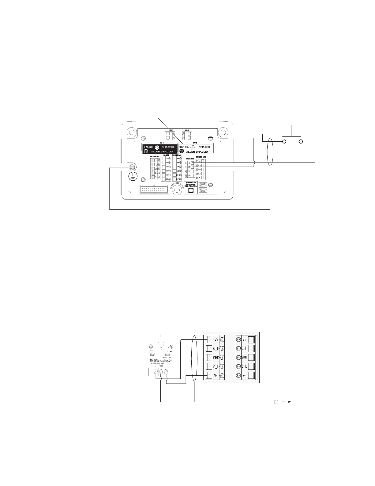
The following illustration shows the wiring base connections. The
2755-IB5S DC input module and the 42SRU-6203 PHOTOSWITCH
receive power from the Package Detect +12V internal power source
in this application. You could also use an external AC or DC power
source. Refer to the AdaptaScan Bar Code Readers User Manual
(Publication No. 2755-837) for more information regarding using an
external power source.
2755-IB5S
To +
To -
To +12V
To
GND
External
Input Contacts
Connecting a Power Supply to the Reader
The circuit must not draw more than 50mA from the Package Detect
terminal block.
The following illustration shows how to connect a 2755-PW46 or
-PW47 power supply to a single bar code reader.
Use a shielded cable (Belden 9316 recommended) to make the
connections. Connect the shield to the ground screw on the reader’s
wiring base.
2755-PW46
Power Supply
24V+
V-
Reader
Ground Screw
on Wiring Base
Publication 2755-6.8
Page 20
1–3Using the Auto-Load Function
Configuring the Reader
This section shows how to configure the AdaptaScan Reader using
the AdaptaScan software (Catalog No. 2755-ASN).
The procedures in this section show how to:
• configure a bar code label and symbol
• define a DeviceNet address
• configure the scanner
• configure the decoder trigger
• configure the discrete input module
• configure the match table, package and autoload trigger source
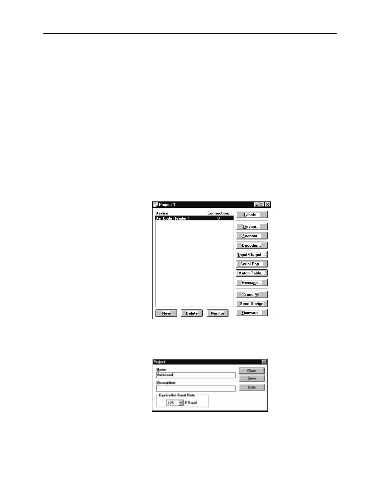
Create a New Project
1. Select New from the Project menu to create a new project.
2. Click the New button to add a bar code reader (Bar Code Reader
1) to the project.
3. Choose Edit from the Project menu to rename the project
AutoLoad.
4. Click Save to save the project under the new name and then click
Close to return to the Project dialog.
Publication 2755-6.8
Page 21
1–4 Using the Auto-Load Function
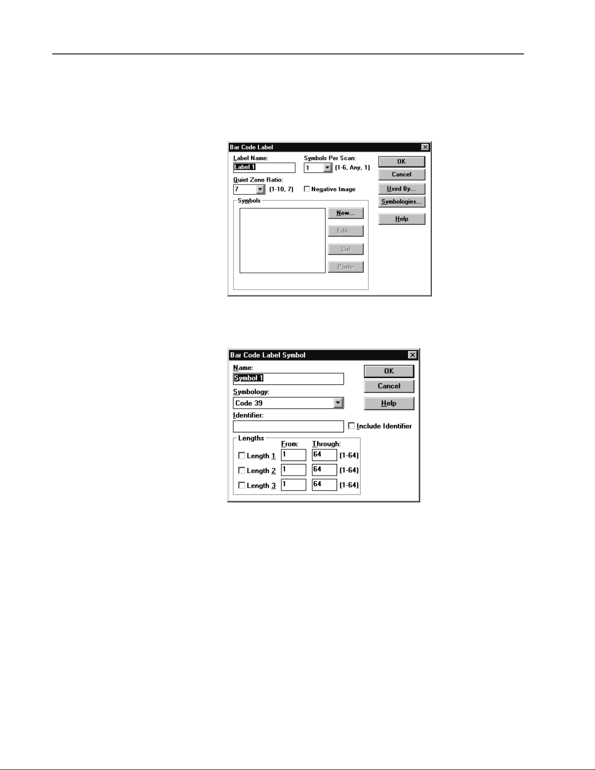
Define a Bar Code Label
1. Click the Labels button to open the Bar Code Labels dialog.
2. Click the New button to add a label.
3. Click the New button to add a symbol.
4. Select the symbology and define attributes such as Identifier and
Lengths.
5. Click OK until you return to the Bar Code Labels dialog.
6. Click Save to save the new label setup.
7. Click Close to return to the main Project dialog.
Publication 2755-6.8
Page 22
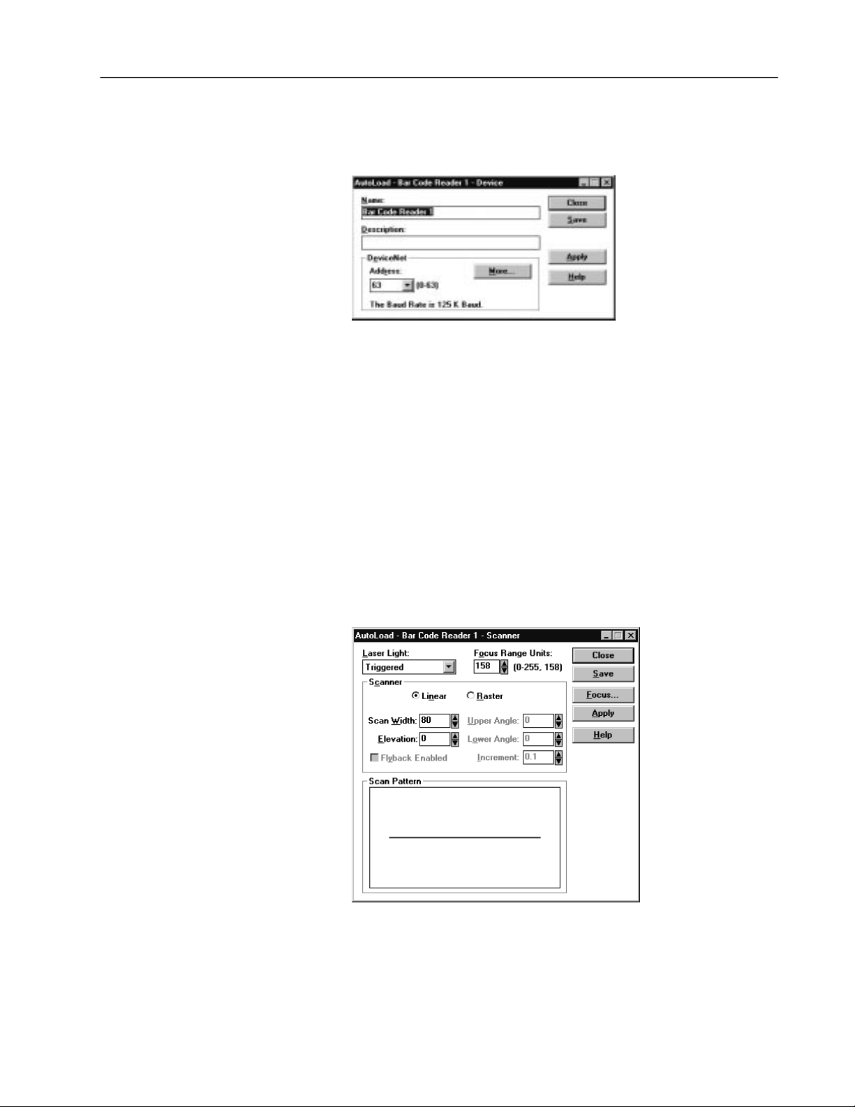
Define the DeviceNet Address
1. Click the Device button on the Project dialog.
2. Select a DeviceNet address.
3. Connect the 2755-NC43 or -NC48 Configuration Cable to the
reader.
4. Click the Apply button to send the DeviceNet address to the
reader.
1–5Using the Auto-Load Function
5. Click Save and Close to return to the main Project dialog.
Configure the Scanner
1. Click the Scanner button on the Project dialog to open the
Scanner dialog.
2. Configure the scan pattern and use the Focus procedure for
optimum scanner focus.
3. Click the Close button to return to the main Project dialog.
Publication 2755-6.8
Page 23
1–6 Using the Auto-Load Function
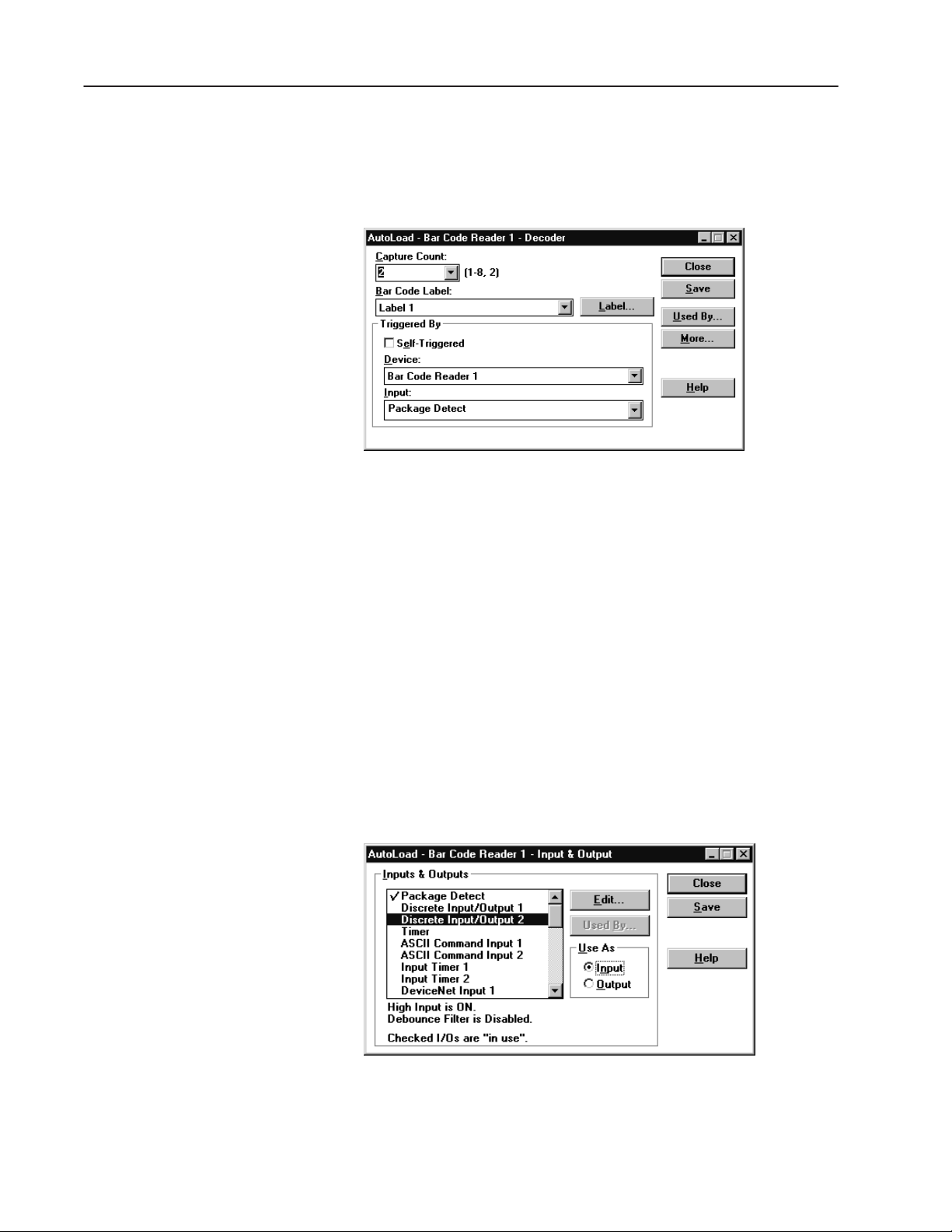
Configure the Decoder
1. Click the Decoder button from the main Project dialog.
2. Under Triggered By, select Package Detect from the Input list.
3. Click the Save button.
4. Click the Close button and return to the main Project dialog.
Configure the Discrete Input Module
The application uses a discrete input module to trigger the
Auto-Load function. The following procedure defines one of the
two input/output modules available in the AdaptaScan Bar Code
Reader as an input.
1. Click the Input/Output button on the main Project dialog.
2. Under Inputs & Outputs, select Discrete Input/Output 2. This is
the location of the 2755-IB5S DC Input Module in the reader’s
wiring base.
3. Under Use As, select Input.
Publication 2755-6.8
4. Click the Save button.
5. Click the Close button to return to the main Project dialog.
Page 24
1–7Using the Auto-Load Function
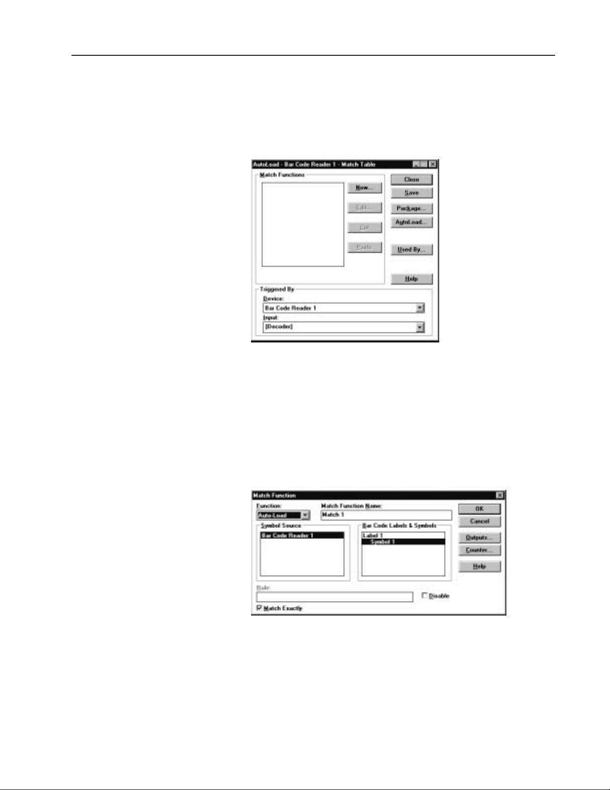
Configure the Match Table
The following procedure defines the contents of the match table and
the source of the symbol to be matched.
1. Click the Match Table button on the main Project dialog.
2. Click the New button to open the Match Function dialog.
3. Select the following parameters for the Match Function:
• Under Function, select Auto-Load
• Under Symbol Source, select Bar Code Reader 1
• Under Bar Code Labels & Symbols, select Symbol 1 under
Label 1
• Check (enable) the Match Exactly check box
4. Click the OK button to return to the Match Table dialog.
Publication 2755-6.8
Page 25
1–8 Using the Auto-Load Function
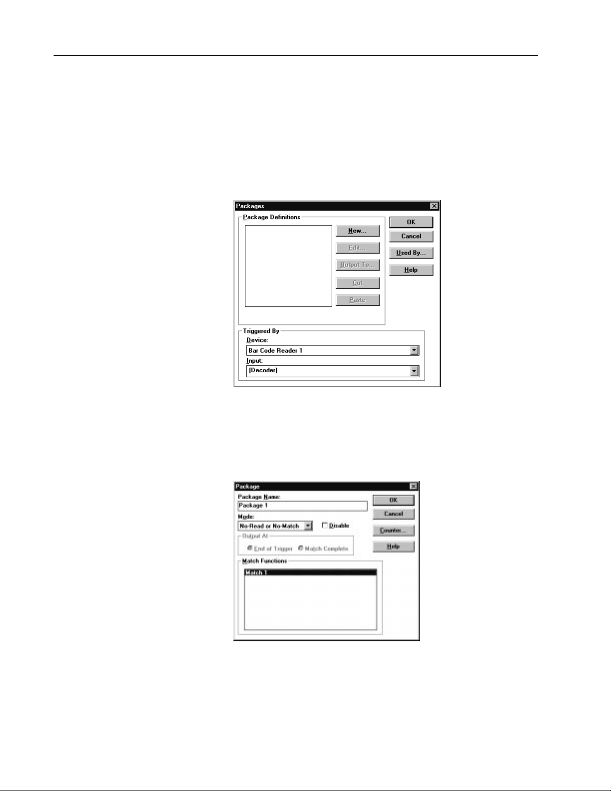
Configure a Package
When the application is running, the I/O 1 LED energizes (no output
module is actually installed in wiring base) when a No-Match or
No-Read occurs. The following procedure defines this package
function.
1. From the Match Table dialog, click the Package button to open
the Packages dialog.
2. Click the New button to create a package.
3. Under Mode, select No-Read or No-Match.
4. Select Match 1 under Match Functions.
5. Click OK to return to the Packages dialog.
Publication 2755-6.8
Page 26
6. Click the Output To button to open the Package Outputs dialog.
7. Under Available Outputs, select Discrete Input/Output 1.
8. Click the Add>> button to add this selection under Output To:
Note: Discrete Input/Output 2 does not appear as an Available
Output because it was previously defined as an input.
1–9Using the Auto-Load Function
9. Click OK until you return to the Match Table dialog.
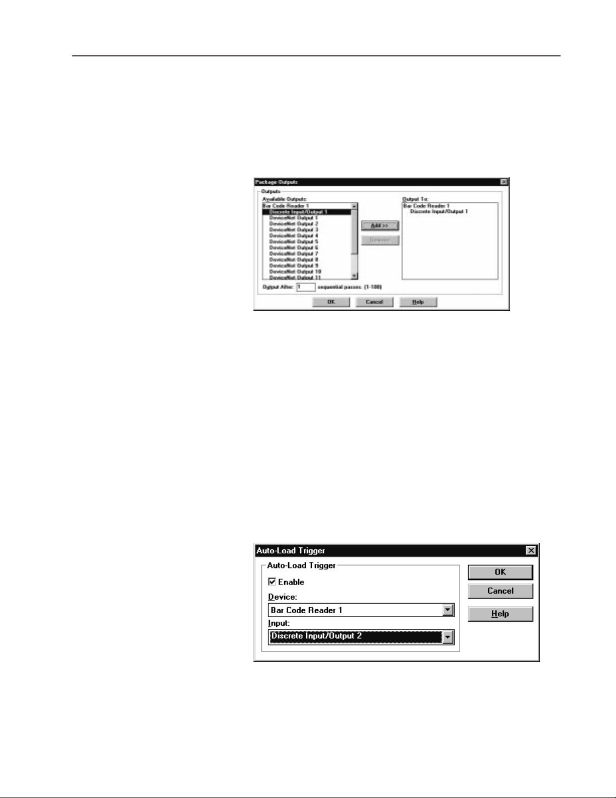
Configure the Auto-Load Trigger Source
The application uses a discrete input module (Discrete Input/Output
2) to activate the Auto-Load function. The following procedure
shows how to configure the input which will activate Auto-Load.
1. Click the AutoLoad button from the Match Table dialog.
2. Under Auto-Load Trigger:
• check the Enable check box.
• select Bar Code Reader 1 from the Device list.
• select Discrete Input/Output 2 from the Input list.
3. Click OK to return to the Match Table dialog.
4. Click Save and then Close to return to the Project dialog.
Publication 2755-6.8
Page 27

1–10 Using the Auto-Load Function
Sending the Configuration to the Reader
Running the Application
From the main Project dialog, click the Send Device button to
download the configuration to the bar code reader.
Use the Monitor dialog to verify bar code labels as they are decoded.
When the application is running, bar code data is autoloaded by
triggering the decoder (with Package Detect) when the desired
symbol is scanned and decoded. If the bar code data is unreadable or
does not match the autoloaded match string, I/O LED 1 turns on.
The following illustration shows the auto-load sequence using a
Package Detect as a decoder trigger.
Package Detect
Auto-Load Trigger remains on until
Package Detect is turned off
Auto-Load Trigger
Auto-Load trigger prior to
Package Detect
For more information on using Auto-Load, refer to chapter 10 in the
AdaptaScan Software User Manual (Publication No. 2755-838).
Publication 2755-6.8
Page 28

Using ASCII Command Input
Overview
Hardware Requirements
This application describes how to configure an AdaptaScan Bar
Code Reader to receive ASCII commands from a terminal emulator
over an RS-232 link:
• Terminal Emulator in Windows 3.1
• HyperTerminal in Windows 95
One character ASCII commands trigger the reader to start/stop
scanning. For each trigger command the reader receives, it echoes a
bar code string on the emulator.
The application includes the necessary cable diagrams and
configuration information for the AdaptaScan Bar Code Reader.
The hardware items required for this application are:
• 2755-SN3, -SN5 or -SN8 AdaptaScan Bar Code Reader
• 2755-NB40 or -NB41 Wiring Base
• 2755-NC43 or -NC48 Configuration Cable
• 2755-PW46 or -PW47 Power Supply
• Computer running Windows 3.1 (or later) or Windows 95
• 9-to-25 Pin Adapter (for computers with a 25-pin COM port)
Software Requirements
Related Publications
The software requirements for this application are:
• 2755-ASN AdaptaScan Offline Programming Software
• Terminal Emulator in Windows 3.1 or HyperTerminal in
Windows 95
Publications you may want to refer to include:
Publication Description
2755-837 AdaptaScan Bar Code Readers User Manual
2755-838 AdaptaScan Software User Manual
Publication 2755-6.8
Page 29
2–2 Using ASCII Command Input
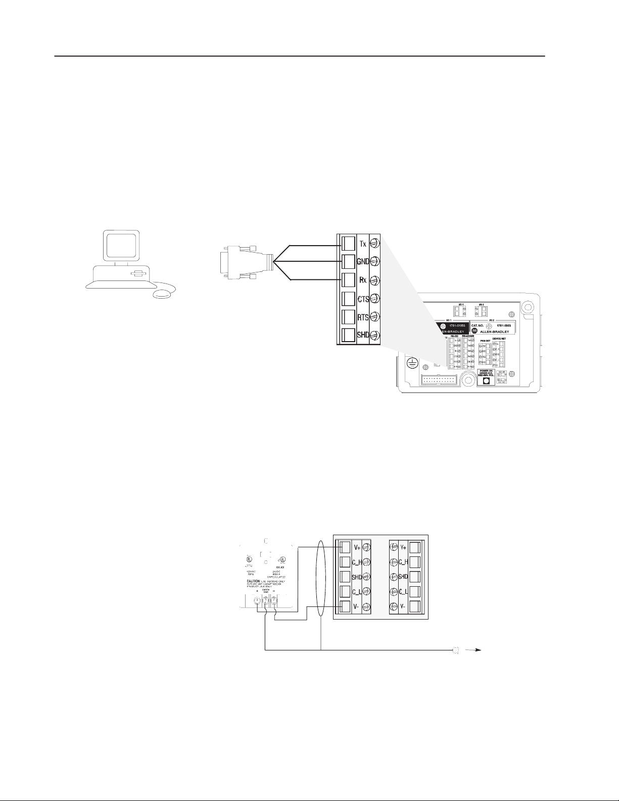
Connecting a Computer to the Reader
with Your Computer RS-232 Port
The following illustration shows the wiring base connections
between the AdaptaScan Bar Code Reader and the personal
computer. This RS-232 serial connection is used to download ASCII
commands to the reader and to display bar code messages on the
terminal emulator.
Create a cable using Belden 8303 (or equivalent) and a connector (to
match your computer’s RS-232 port). The other end of the cable is
wired to the RS-232 port in the reader wiring base.
Use Belden 8303 (or equivalent)
To Computer
To Connector Compatible
RX
GND
TX
Wiring Base of Reader
Connecting a Power Supply to the Reader
The following illustration shows how to connect a 2755-PW46 or
-PW47 power supply to a single bar code reader.
Use a shielded cable (Belden 9316 recommended) to make the
connections. Connect the shield to the ground screw on the reader’s
wiring base.
2755-PW46
Power Supply
24V+
V-
Reader
Ground Screw
on Wiring Base
Publication 2755-6.8
Page 30
2–3Using ASCII Command Input
Configuring the Reader
This section shows how to configure the AdaptaScan Reader using
the AdaptaScan Software (Catalog No. 2755-ASN).
The procedures in this section show how to:
• configure a bar code label and symbol
• define a DeviceNet address
• configure the scanner
• configure the decoder trigger for ASCII Command Input
• configure one character ASCII commands to start/stop scanning
• configure the serial port for terminal emulation
• define the format and content of messages
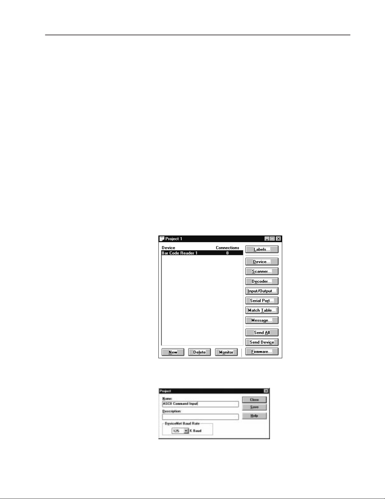
Create a New Project
Create a new project named ASCII Command Input for one
AdaptaScan Bar Code Reader (Bar Code Reader 1).
1. Choose New from the Project menu to create a new project.
2. Click the New button to add a bar code reader (Bar Code Reader
1) to the project.
3. Choose Edit from the Project menu to rename the project ASCII
Command Input.
4. Click Save to save the project under the new name and then Close
to return to the Project dialog.
Publication 2755-6.8
Page 31

2–4 Using ASCII Command Input
1. Click the Labels button to open the Bar Code Labels dialog.
2. Click the New button to define a label.
Define the Bar Code Label
3. Click the New button to define a symbol for the label.
4. Select the symbology and define attributes such as Identifier and
Lengths.
5. Click OK until you return to the Bar Code Labels dialog.
6. Click Save and then Close to return to the main Project dialog.
Publication 2755-6.8
Page 32

Define the DeviceNet Address
1. Click the Device button on the Project dialog.
2. Select a DeviceNet address.
3. Connect the 2755-NC43 or -NC48 Configuration Cable to the
reader.
4. Click the Apply button.
5. Click Save and Close to return to the Project dialog.
2–5Using ASCII Command Input
Configure the Scanner
1. Click the Scanner button on the Project dialog to open the
Scanner dialog.
2. Configure the scan pattern and use the Focus procedure for
optimum scanner focus.
3. Click the Close button and return to the Project dialog.
Publication 2755-6.8
Page 33

2–6 Using ASCII Command Input
1. Click the Decoder button from the main Project dialog.
2. Under Triggered By, select ASCII Command Input 1 from the
Configure the Decoder Trigger
This section defines ASCII Command Input 1 as the trigger for the
reader’s decoder.
Input list.
3. Click the Save button.
4. Click the Close button and return to the main Project dialog.
Configure the ASCII Commands
The following procedure defines the ASCII commands that will
trigger the decoder to start/stop scanning.
1. Click the Input/Output button on the main Project dialog.
2. Under Inputs & Outputs, select ASCII Command Input 1.
Publication 2755-6.8
Page 34

2–7Using ASCII Command Input
3. Click the Edit button to open the ASCII Command Input dialog.
The default ASCII commands for triggering the decoder are two
character commands:
• BS (Begin Scan)
• ES (End Scan)
This application uses one character ASCII commands to trigger
the decoder.
• B (Begin Scan)
• E (End Scan)
4. In the Turn On field, type the letter B. (The command is case
sensitive.)
5. In the Turn Off field, type the letter E. If you do not use an E in
the Turn Off field, the trigger will then turn off in 1000 ms. (The
command is case sensitive.)
6. Click the OK button.
7. Click the Save button to save the ASCII command definitions.
8. Click the Close button and return to the main Project dialog.
Publication 2755-6.8
Page 35

2–8 Using ASCII Command Input
1. Click the Serial Port button on the main Project dialog.
Configure the Serial Port
This section configures the RS-232 serial port so that it is compatible
with the Terminal Emulator in Windows 3.1 or HyperTerminal in
Windows 95.
2. Verify that Terminal is selected in the Protocol list box.
3. In the Maximum Length field, type 1.
With the Maximum Length set to 1, only one character is
downloaded to the reader through the terminal via RS-232 port.
If a message is configured, all bar code strings are read and
uploaded to the terminal via RS-232 port.
If the Maximum Length is set to 2, only two characters are
downloaded to the reader through the terminal via RS-232 port.
However, if a message is configured, only 2 bar code data
characters are uploaded to the terminal. The same is true for a
setting 3.
4. Select RS232 from the Connection list box.
Publication 2755-6.8
Page 36

5. Click the Edit button under Protocol.
6. Under Flow Control, select None.
7. Click OK to close the dialog.
8. Click the Save button to save the serial configuration.
2–9Using ASCII Command Input
9. Click Close to return to the main Project dialog.
Publication 2755-6.8
Page 37

2–10 Using ASCII Command Input
1. Click the Message button from the main Project dialog.
Create a Message
This section defines the content of the message sent from the reader
to the terminal emulator.
2. Under Triggered By, check the Enable check box.
3. Under Device, select Bar Code Reader 1.
4. Under Input, select [Decoder].
5. Click the New button to define a message field.
6. Under Symbol Source, select Bar Code Reader 1.
7. Under Bar Code Labels & Symbols, select Symbol 1.
8. Check (enable) the Match Exactly check box.
9. Click the Edit button to open the Message Field Edit dialog.
Publication 2755-6.8
Page 38

10. Under Replacement Strings, type nr in the Fail: field.
Bar code data is sent to the emulator on a valid read. The Fail
string sends the characters “nr” when a no read occurs.
11. Click OK to return to the Message Field dialog.
12. Click OK to return to the Message dialog.
2–11Using ASCII Command Input
Define the Message Format
This section defines the format of the message to display on the
terminal emulator.
1. Click the Format button from the Message dialog.
2. In the Trailer field, type \r\n (Carriage Return, Line Feed).
3. Under Message Destination, select Serial Port.
4. Click OK to return to the Message dialog.
5. Click the Save button and then the Close button to return to the
Project dialog.
Publication 2755-6.8
Page 39

2–12 Using ASCII Command Input
Sending the Configuration to the Reader
Running the Application
From the main Project dialog, click the Send Device button to
download the configuration to the bar code reader.
If your computer does not have two serial ports, switch the
2755-NC43 or -NC48 cable to the serial cable already wired to the
AdaptaScan Reader’s wiring base.
In the following illustration:
• ASCII command B is entered to trigger the decoder to start
scanning.
• ASCII command E is entered to stop scanning. A timeout occurs
if an E is not entered.
• Bar code data is displayed on the terminal emulator.
You must type B to trigger the decoder again and display the next bar
code string on the emulator.
Terminal Emulator Example
B
E
12345678
B
E
abcdefg
B
E
12345678
ASCII Turn On command
ASCII Turn Off command
Bar code data from AdaptaScan Reader
Publication 2755-6.8
Page 40

Downloading Match Codes
from a Host Device
Overview
Hardware Requirements
Software Requirements
This application describes how to download match codes to the bar
code reader from a terminal emulator using an RS-232 connection.
It also describes how to download other host commands using the
same procedures.
The hardware items required for this application are:
• 2755-SN3, -SN5, -SN8 AdaptaScan Bar Code Reader
• 2755-NB40 or -NB41 Wiring Base
• 2755-PW46 or -PW47 Power Supply
• 2755-NC43 or -NC48 Configuration Cable
• Communication Cable with Connector for PC
(Belden 8303 or equivalent)
• Computer running Windows 3.1 (or later) or Windows 95
• 9-to-25 Pin Adapter (for Computer with 25-pin COM port)
The software requirements for this application are:
• 2755-ASN AdaptaScan Offline Programming Software
• Terminal Emulator in Windows 3.1 or HyperTerminal in
Windows 95
Related Publications
Related publications include:
Publication Description
2755-837 AdaptaScan Bar Code Readers User Manual
2755-838 AdaptaScan Software User Manual
Publication 2755-6.8
Page 41

3–2 Downloading Match Codes from a Host Device
Connecting a Computer to the Reader
with Your Computer RS-232 Port
The following illustration shows the wiring base connections
between the AdaptaScan Bar Code Reader and the personal
computer. This RS-232 serial connection is used to download match
codes to the reader from a terminal emulator. Do not connect the
cable to the computer until after the application is downloaded to the
reader (see page 3–10).
Create a cable using Belden 8303 (or equivalent) and a connector (to
match your computer’s RS-232 port). The other end of the cable is
wired to the RS-232 port in the reader wiring base.
Use Belden 8303 (or equivalent)
To Computer
To Connector Compatible
RX
GND
Tx
Wiring Base of Reader
Connecting a Power Supply to the Reader
The following illustration shows how to connect a 2755-PW46 or
-PW47 power supply to a single bar code reader.
Use a shielded cable (Belden 9316 recommended) to make the
connections. Connect the shield to the ground screw on the reader’s
wiring base.
2755-PW46
Power Supply
24V+
V-
Reader
DeviceNet Connector
Ground Screw
on Wiring Base
Verify the connection by applying power to the wiring base and
observing the polarity LED. The LED should be green. If the LED
is red, the polarity needs to be reversed. Disconnect power from
wiring base until the reader is installed.
Publication 2755-6.8
Page 42

3–3Downloading Match Codes from a Host Device
Configuring the Reader
This section shows how to configure one the AdaptaScan Bar Code
Readers using the AdaptaScan Software (Catalog No. 2755-ASN).
The procedures in this section show how to:
• define the DeviceNet node address of the AdaptaScan Reader
• configure a bar code label and symbol
• configure the scanner
• configure the decoder trigger
• configure the serial port
• configure the format of messages and the message destination
The steps may vary for some procedures because of the different
requirements of applications. For example, the bar code labels may
vary from one application to the next.
Create a New Project
This section adds a bar code reader to a new project and then
renames the project Download Match Codes.
1. Choose New from the Project menu to create a new project.
2. Click the New button to add a bar code reader (Bar Code Reader
1) to the project.
3. Choose Edit from the Project menu to rename the project
Download Match Codes.
4. Click Save to save the project under the new name and then Close
to return to the Project dialog.
Publication 2755-6.8
Page 43

3–4 Downloading Match Codes from a Host Device
Define the Bar Code Label
This section configures the reader to scan/decode Interleaved 2 of 5
symbols.
1. Click the Labels button to open the Bar Code Labels dialog.
2. Click the New button to define a label.
3. Click the New button to define Symbol 1.
4. From the Symbology list box, select I 2 of 5.
To edit parameters of the selected symbology, click the
Symbologies button.
5. Click OK until you return to the Bar Code Labels dialog.
6. Click Save and then Close to return to the main Project dialog.
Publication 2755-6.8
Page 44

Define the DeviceNet Address
1. Click the Device button on the Project dialog.
2. Select a DeviceNet address.
3. Connect the 2755-NC43 or -NC48 Configuration Cable to the
Reader.
4. Click the Apply button.
5. Click the Close button and return to the Project dialog.
3–5Downloading Match Codes from a Host Device
Configure the Scanner
1. Click the Scanner button on the Project dialog to open the
Scanner dialog.
2. Configure the scan pattern and use the Focus procedure for
optimum scanner focus.
3. Click the Close button and return to the Project dialog.
Publication 2755-6.8
Page 45

3–6 Downloading Match Codes from a Host Device
Configure the Decoder Trigger
Bar Code Reader 1 is triggered by a Timer. The Timer is typically
used during initial setup to simulate a package detector.
The Timer is set for a specified On Time (1 second) and Off Time (1
second).
1. Click the Decoder button from the main Project dialog.
2. Under Triggered By, select Timer from the Input list.
3. Click the Save button and the Close to return to the main Project
dialog.
Publication 2755-6.8
Page 46

3–7Downloading Match Codes from a Host Device
Configure the Serial Port
Configure the parameters of the serial port to match the host device.
1. Click the Serial Port button from the main Project dialog.
2. Under Protocol, select:
• select Terminal
• check (enable) the Scanner Protocol check box
Scanner Protocol is used when a host (e.g., PLC or computer) is
connected to a serial port in the reader’s wiring base.
3. From the Connection list box, select RS232.
4. Click the Edit button to configure the parameters for Terminal
protocol.
5. In the Trailer text box, type \r\n (inserts carriage return and line
feed).
6. Check (enable) the Hex Conversion check box.
7. Click OK to return to the Serial Port dialog.
8. Click Save and then the Close button to return to the Project
dialog.
Publication 2755-6.8
Page 47

3–8 Downloading Match Codes from a Host Device
Configuring a Match Entry and I/O Indicator LED
The application turns on output 1 when a symbol is read. This
provides a convenient method of determining whether or not the
reader is decoding a label. The discrete output is turned on by the
match table.
1. Click the Match Table button on the main Project dialog.
2. Click the New button to open the Match Function dialog.
3. Under Function, select Match Entry from the list box.
Match Entry specifies that a match occurs whenever decoded bar
code data matches the Rule: entry.
4. Under Symbol Source, select Bar Code Reader 1.
5. Under Bar Code Labels & Symbols, select Symbol 1.
6. Check (enable) the Match Exactly check box.
Match Exactly specifies that ASCII characters are matched
instead of a metacharacter rule (metacharacters are not used in
this example).
Publication 2755-6.8
Page 48

3–9Downloading Match Codes from a Host Device
7. Click the Outputs button to specify which output activates when a
match occurs.
8. Under Available Outputs, select Discrete Input/Output 1.
9. Click the Add>> button to add this selection to the Output To:
area.
Sending the Configuration to the Reader
10. Click OK until you return to the Match Table dialog.
11. Click Save and then Close to return to the Project dialog.
From the main Project dialog, click the Send Device button to
download the configuration to the bar code reader.
Publication 2755-6.8
Page 49

3–10 Downloading Match Codes from a Host Device
Finding Match Table Instances
Connecting the Computer to the RS-232 Port
When you download match codes from a host, you need the instance
number of the match table. Do not assume that Match 1 = Instance
1, Match 2 = Instance 2.
From the Project menu, select Print. The printout will show the class
and instance numbers.
Disconnect the 2755-NC43 or -NC48 Configuration Cable from the
personal computer. Connect the communication cable previously
connected to the RS-232 connector in the wiring base to the
computer’s RS-232 serial COM port.
Power source required
See reader user manual
Communication Cable
Connect to RS–232 Port
Personal Computer
Publication 2755-6.8
Page 50

3–11Downloading Match Codes from a Host Device
Downloading Match Codes
To download match codes from your computer you must:
1. Convert the match string to hex.
2. Enter the match string in the proper data packet format.
3. Send the data packet (containing the string) to the reader.
Convert the Bar Code String to Hex
Convert the bar code string you want to send to the reader to the
hexadecimal ASCII equivalent value. For example:
Bar Code String:
Converted Hex Value:
Converted Bar Code Length Value:
In the bar code length shown above, if the number of characters 04
were changed to 14, the hexadecimal value would be 0E. This
hexadecimal value is written as 0E00.
0 2 0 0
30 32 30 30
0 4 0 0
Place the String in the Data Packet
The bar code string is sent in a data packet having this format:
3F 10 CE 01 00 03 04 00 30 32 30 30
Instance
Number
in Bar Code String
(in hexadecimal)
The following are descriptions of the data packet:
3F = DeviceNet Address (3F= 63, each reader has unique address)
10 = Set attribute (single request)
CE = 206 = Class (always 206 for match table)
01 = Instance Number (LSB)
00 = Instance Number (MSB)
03 = Attribute Number – Rule
04 = Length of String (LSB)
00 = Length of String (MSB)
30 = ASCII “0”
32 = ASCII “2”
30 = ASCII “0”
30 = ASCII “0”
Bar Code String# of Characters
Note: You can use the Windows calculator to convert decimal
values to hexadecimal.
Publication 2755-6.8
Page 51

3–12 Downloading Match Codes from a Host Device
Send Data to the Reader
1. Use the Windows terminal function to send the data. Locate the
terminal icon (usually within the Accessories group icon).
2. Open the terminal icon.
Publication 2755-6.8
3. From the Settings menu open the Communications dialog and
make sure that the settings match the reader serial port settings.
Note: 9600 Baud must be selected.
Page 52

3–13Downloading Match Codes from a Host Device
4. From the Settings menu open the Terminal Preferences dialog and
select Local Echo and Outbound (CR/LF).
5. Return to the terminal window and enter the data string to
download. All characters must be in uppercase.
3F10CE010003040030323030
6. Press Return to send the data.
The terminal window will display the response.
3F10CE010003040030323030
3F90
The response of 3F90 indicates a good write of the match code.
3F90
Address (3F = 63) Response Code (90 = Successful)
(94 = Fail)
Note: Refer to the next page for a description of the response
code format and codes.
You can verify whether or not a correct match code was
downloaded by placing a bar code label in front of the reader so
that it is scanned. Observe the Output #1 LED on the top of the
reader. When the downloaded match code matches a scanned
label, the output will turn on.
If you receive a response code other than 90, refer to the the
response code chart on the next page.
Publication 2755-6.8
Page 53

3–14 Downloading Match Codes from a Host Device
Response Codes
Response codes have the following format:
Byte Contents
0
1
2
3
General Error Codes
Code (hex) Name
02 Resource unavailable
08
09 Invalid attribute value
0B
0C
0E Attribute not settable
0F
10
11 Reply data too large
13 Not enough data
14 Attribute not supported
15 Too much data
16 Object does not exist
18 No stored attribute data
19 Store operation failure
D0-FF Class specific
requested mode/state
Object cannot perform service
in its current mode/state
Access permission
does not allow service
Device’s mode/state does
not allow object to perform
Mac ID (Address)
94 = Error Response
x = General Error Code
x = Additional Code
Service
not supported
Already in
service
Publication 2755-6.8
Page 54

You can download other host commands using the same procedures
Downloading Other Host
Commands
described in the match code example. The following tables provide
the commands and responses for the other host commands (all values
are hexadecimal).
Read Performance Indicator Command Read Performance Indicator Response
Packet Contents Data Sent Packet Contents Response
DeviceNet Address 3F* DeviceNet Address 3F
Get Performance Request 4C Get Performance Response CC
Class C8 Data (LSB) 01
Instance Number (LSB) 01 Data (MSB) 00
Instance Number (MSB) 00
*3F = Address 63, modify as required
Reset Package Counter Command Reset Package Counter Response
Packet Contents Data Sent Packet Contents Response
DeviceNet Address 3F* DeviceNet Address 3F
Set Attribute Request 10 Set Attribute Response 90
Class D2
Instance Number (LSB) 00
Instance Number (MSB) 00
Attribute Number–
Reset Counters
Data 01
*3F = Address 63, modify as required
09
3–15Downloading Match Codes from a Host Device
Read Match Counters Command Read Match Counters Response
Packet Contents Data Sent Packet Contents Response
DeviceNet Address 3F* DeviceNet Address 3F
Get Attribute Request 0E Get Attribute Response 8E
Class CE Data 6C, 08, 00, 00
Instance Number (LSB) 01
Instance Number (MSB) 00
Attribute Number 08
*3F = Address 63, modify as required
Read Package Counters Command Read Package Counters Response
Packet Contents Data Sent Packet Contents Response
DeviceNet Address 3F* DeviceNet Address 3F
Get Attribute Request 0E Get Attribute Response 8E
Class D2 Data 6C, 08, 00, 00
Instance Number (LSB) 01
Instance Number (MSB) 00
Attribute Number–
Match Count
*3F = Address 63, modify as required
08
Publication 2755-6.8
Page 55

3–16 Downloading Match Codes from a Host Device
Reset Match Counters Command Reset Match Counters Response
Packet Contents Data Sent Packet Contents Response
Response Codes 3F* DeviceNet Address 3F
Set Attribute Request 10 Set Attribute Response 90
Class CE
Instance Number (LSB) 00
Instance Number (MSB) 00
Attribute Number-
Reset Counters
Data 01
*3F = Address 63, modify as required
0B
Read Message Command Read Message Response
Packet Contents Data Sent Packet Contents Response
DeviceNet Address 3F* DeviceNet Address 3F
Get Attribute Request 0E Get Attribute Response 8E
Class CC Data (LSB) 04
Instance Number (LSB) 00 Data (MSB) 00
Instance Number (MSB) 00 ASCII Message Data 30*
Attribute Number - Message 14 ASCII Message Data 32
*3F = Address 63, modify as required ASCII Message Data 30
ASCII Message Data 30
* Example data = 0200
Read LED Status Command Read LED Status Response
Packet Contents Data Sent Packet Contents Response
DeviceNet Address 3F* 3F 3F
Read LEDS Request 43 Read LEDS Response C3
Class CB I/O 1 See Table Next Page
Instance Number (LSB) 01 I/O 2 See Table Next Page
Instance Number (MSB) 00 Trigger / Read See Table Next Page
*3F = Address 63, modify as required On Symbol See Table Next Page
Laser On See Table Next Page
Module See Table Next Page
Network See Table Next Page
Publication 2755-6.8
Page 56

Set Output Timer Command Set Output Timer Response
0
1
3
3
Packet Contents Data Sent Packet Contents Response
DeviceNet Address 3F* DeviceNet Address 3F
Set Attribute Request 10 Set Attribute Response 90
Class D0
Instance Number (LSB) 02
Instance Number (MSB) 00
Attribute Number - Max Time 09
Data (LSB) FA
Data (MSB) 00
*3F = Address 63, modify as required
** Time in milliseconds
LED Status Response
Data at Indicated Bit Address = LED State
Byte Bits LED Indicator
0-2 I/O 1 OFF ON
3-5 I/O 2 OFF ON
0-2 TRIGGER / READ
3-5 ON SYMBOL
0-2 LASER ON OFF ON
2
3-5 MODULE No Power
0-2 NETWORK
3-5
0 = Off 1 = Yellow 2 = Green 3 = Red
No
Trigger
Not Read-
ing
Triggered
Reading
Valid
Read
DeviceOKHardware
Fault
DeviceNetOKDeviceNet
Fault
4 = Not
Used
5 = Flash
Yellow
Read
<100%
6 = Flash
Green
Power Up
Estab-
lished
3–17Downloading Match Codes from a Host Device
7 = Flash
Red
Minor
Fault
No
Response
Publication 2755-6.8
Page 57

Downloading Match Codes via
DH485 Protocol with an SLC
5/03 or SLC 5/04 Controller
Overview
Hardware Requirements
This application describes how to download match codes to the bar
code reader from an SLC 5/03 or SLC 5/04 controller using DH485
protocol in master and slave modes.
DH485 Master is used for bar code data traveling at medium or slow
speeds. Data is sent to the SLC 5/03 or SLC 5/04 controller whether
it was requested or not by the SLC 5/03 or SLC 5/04 controller.
DH485 Slave is used for bar code data traveling at high speeds. The
SLC 5/03 or SLC 5/04 controller initiates the request for bar code
data.
Refer to chapter 3 for a listing of additional host commands and
response codes.
The hardware items required for this application are:
• 2755-SN3, -SN5, or -SN8 AdaptaScan Bar Code Reader
• 2755-PW46 or -PW47 Power Supply
• 2755-NC43 or -NC48 Configuration Cable
• 2755-NB40 or -NB41 Wiring Base (Ser. A/Rev. B or higher)
• 1747-L532, -L541, -L542, or -L543 SLC Processor
• 1746-A4, -A7, -10, or -A13 Chassis
• 1746-P3 Power Supply
• 1747-CP3 RS-232 Programming Cable
• 1747-AIC Isolated Link Coupler or 1761-NET-AIC Advanced
Interface Converter
• 1747-PIC RS-232/DH-485 Converter
• Computer running Windows 3.1 (or later) or Windows 95
• 9-to-25 Pin Adapter (for computers with a 25-pin COM port)
Software Requirements
The software requirements for this application are:
• 2755-ASN AdaptaScan Offline Programming Software
• 9323-PA2E Advanced Programming Software. (The original
ICOM SLC software is not compatible with this AdaptaScan
network.)
Publication 2755-6.8
Page 58

4–2 Downloading Match Codes via DH485 Protocol with an SLC 5/03 or SLC 5/04 Controller
Related Publications
Connecting a Power Supply to the Reader
Related publications include:
Publication Description
2755-837 AdaptaScan Bar Code Readers User Manual
2755-838 AdaptaScan Software User Manual
1747-6.2
9399-APSUM-11.15.95 Advanced Programming Software User Manual
SLC 500 Modular Hardware Style Installation and
Operation Manual
The following illustration shows how to connect a 2755-PW46 or
-PW47 power supply to a single bar code reader.
Use a shielded cable (Belden 9316 recommended) to make the
connections. Connect the shield to the ground screw on the reader’s
wiring base.
2755-PW46
Power Supply
24V+
Reader
Connecting to the DH-485 Network
V-
Ground Screw
on Wiring Base
The wiring base of the AdaptaScan Reader has an RS-485/RS-422
terminal block for point-to-point or network connections.
This section shows three connection options:
• Connecting readers to SLC 5/03
• Connecting readers to SLC 5/04 using two 1747-AIC Modules
• Connecting readers to SLC 5/04 using one 1747-AIC Module
Note: You can use the 1761-NET-AIC Advanced Interface
Converter in place of the 1747-AIC Module.
Important: The DH485 network cable requires proper shielding,
grounding and termination. Refer to Data
Highway/Data Highway Plus/Data Highway DH485
Cable Installation Manual (Publication 1770-6.2.2).
Publication 2755-6.8
Page 59

Important: When setting up a DH-485 network using an
AdaptaScan, make sure that the nodes on the network
are in sequential order. The SLC 5/03 or 5/04 should be
Node 1, and AdaptaScan should be Node 2, and each
node after that should be 3, 4, and so forth. If other
DH-485 nodes are needed (i.e. DTAM, etc...), the
AdaptaScan node number(s) must be first. Node gaps
must be avoided in order to prevent the AdaptaScan
from Soliciting of Successor (SOS). By preventing
SOS, bar code throughput is maximized as it is sent to
the SLC. In other words, when setting up the
AdaptaScan via DH-485 the first priority is to process
bar code data instead of finding node gaps.
Connecting Readers to SLC 5/03 Controller
You must use a link coupler if the distance between the reader and
the SLC is greater than 15.2 meters (50 feet). The reader can
connect directly to another RS-485/RS-422 device. Point-to-point
and network connections are the same.
4–3Downloading Match Codes via DH485 Protocol with an SLC 5/03 or SLC 5/04 Controller
RS-485/422
RS-485/422
RS-422
RS-422
Ground
Shield
The end devices on the DH-485 network must be terminated. The
wiring base of the AdaptaScan Reader provides a termination switch.
AdaptaScan Wiring Base
RS-422/RS-485 Terminal
SLC 5/03 Processor
Power
Supply
Termination Switch
1747-AIC Module
Term
A
B
Com
Shield
Chassis Gnd
Computer
1747-PIC
2755-ASN AdaptaScan Software
SLC 500 Advanced Programming Software
Publication 2755-6.8
Page 60

4–4 Downloading Match Codes via DH485 Protocol with an SLC 5/03 or SLC 5/04 Controller
Connecting Readers to SLC 5/04 Controller – 2 AIC Modules
The SLC 5/04 controller requires two 1747-PIC converters and a
power supply to connect to the second 1747-AIC module.
The end devices on a DH-485 network must be terminated. The
wiring base of the AdaptaScan Reader provides a termination switch.
SLC 5/04 Processor
Power
Supply
Channel 0
RS-232
1747-PIC
AdaptaScan Wiring Base
RS-422/RS-485 Terminal
DH-485
1747-AIC Module
Term
A
B
Com
Shield
Chassis Gnd
1747-AIC Module
Term
A
B
Com
Shield
Chassis Gnd
1747-P4
24V dc Power Supply
The 1747-P4 Power Supply provides
power to both 1747-AIC modules (1 AMP,
24V dc). Otherwise use 2 power supplies.
1747-PIC
DH-485 RS-232
Computer
Publication 2755-6.8
Page 61

Power
Supply
Channel 0
RS-232
4–5Downloading Match Codes via DH485 Protocol with an SLC 5/03 or SLC 5/04 Controller
Connecting Readers to SLC 5/04 Controller – 1 AIC Module
The SLC 5/04 controller requires two 1747-PIC converters.
However, you can use an RJ48 Y adapter (8-wire LAN phone jack
plug) to connect the two 1747-PIC modules. The RJ48 Y adapter is
a modular adapter for 4-pair cable which parallels two 4-pair jacks
and one 4-pair modular plug. This adapter eliminates the second
1747-AIC module shown in the previous SLC 5/04 network diagram.
The end devices on a DH-485 network must be terminated. The
wiring base of the AdaptaScan Reader provides a termination switch.
SLC 5/04 Processor
1747-PIC
DH-485
RJ48 Y Adapter
(8-wire LAN Phone Jack Plug)
Available from Anixter Company
Part No: Hubbell BR851-B
Phone: 414-355-0222
1747-AIC Module
Term
A
B
Com
Shield
Chassis Gnd
AdaptaScan Wiring Base
RS-422/RS-485 Terminal
Computer
1747-PIC
DH-485 RS-232
Publication 2755-6.8
Page 62

4–6 Downloading Match Codes via DH485 Protocol with an SLC 5/03 or SLC 5/04 Controller
Configuring Bar Code Reader 1
This section shows how to configure one the AdaptaScan Bar Code
Readers using the AdaptaScan Software (Catalog No. 2755-ASN).
The procedures in this section show how to:
• configure a bar code label and symbol
• define the DeviceNet node address of the AdaptaScan Reader
• configure the scanner
• configure the decoder trigger
• configure the serial port
• configure the format of messages and the message destination
The steps may vary for some procedures because of the different
requirements of applications. For example, the bar code labels may
vary from one application to the next.
Create a New Project
Create a new project named DH485 Match Code Download for the
AdaptaScan Bar Code Readers.
1. Choose New from the Project menu to create a new project.
2. Click the New button to add a bar code reader (Bar Code Reader
1) to the project.
Publication 2755-6.8
3. Choose Edit from the Project menu to rename the project DH485
Match Code Download.
4. Click Save to save the project under the new name and then Close
to return to the Project dialog.
Page 63

Define the Bar Code Label
1. Click the Label button to open the Bar Code Labels dialog.
2. Click the New button to add a label to open the Bar Code Label
dialog.
4–7Downloading Match Codes via DH485 Protocol with an SLC 5/03 or SLC 5/04 Controller
3. Click the New button to add a symbol.
Publication 2755-6.8
Page 64

4–8 Downloading Match Codes via DH485 Protocol with an SLC 5/03 or SLC 5/04 Controller
4. Select a symbology and any other parameters (Identifier, Lengths)
required by your application.
5. Click OK to return to the main Project dialog.
Define the DeviceNet Address
1. Click the Device button to open the Device dialog.
2. Select a DeviceNet address.
Note: The DeviceNet address is not always the same as the
DH-485 node address. A DH-485 node address is assigned later.
3. Connect the 2755-NC43 or -NC48 cable to the reader.
4. Click the Apply button.
Publication 2755-6.8
5. Click Save and Close to return to the Project dialog.
Page 65

Configure the Scanner
1. Click the Scanner button on the Project dialog to open the
Scanner dialog.
2. Configure the scan pattern and use the Focus procedure for
optimum scanner focus.
4–9Downloading Match Codes via DH485 Protocol with an SLC 5/03 or SLC 5/04 Controller
3. Click the Close button and return to the Project dialog.
Configure the Decoder Trigger
This application uses a Timer to trigger the reader’s decoder. The
Timer is typically used during application setup. Refer to
Publication 2755-837 for other input sources that trigger the decoder.
1. Click the Decoder button from the main Project dialog.
2. Under Triggered By, select Timer from the Input list.
3. Click Save and Close to return to the main Project dialog.
Publication 2755-6.8
Page 66

4–10 Downloading Match Codes via DH485 Protocol with an SLC 5/03 or SLC 5/04 Controller
Configure the Serial Port
1. Click the Serial Port button from the Project dialog.
2. Set the parameters as follows:
• From the Protocol list box, select DH-485
• From the Baud Rate list box, select 19,200
• Click the Scanner Protocol button
• From the Connection list box, select RS485
The Serial Port must match the host configuration.
3. Click the Edit button to select either DH485 Slave Mode or
DH485 Master Mode.
Publication 2755-6.8
Page 67

DH485 Slave Mode
1. Click the Protocol Edit button in the Serial Port dialog.
2. Edit the parameters as follows:
• Click the PCCC Enabled box
• From the Master/Slave box, select Slave
• From the Node box, select 2
This is the DH485 node address.
4–11Downloading Match Codes via DH485 Protocol with an SLC 5/03 or SLC 5/04 Controller
3. Click OK to return to the main Serial Port dialog.
4. Click Save and Close to return to the main Project dialog.
Publication 2755-6.8
Page 68

4–12 Downloading Match Codes via DH485 Protocol with an SLC 5/03 or SLC 5/04 Controller
DH485 Master Mode
1. Click the Protocol Edit button in the Serial Port dialog.
2. Set the parameters as follows:
• From the Master/Slave box, select Master
• From the Destination Node box, select 1
This is the SLC node where the decoded bar codes are sent.
• From the Maximum Node box, select 2
This is the number of nodes on the network.
• From the N9:Offset box, select 100 which is the default
This is the SLC destination address where the decoded bar
codes are sent. N9: is reserved for communications. Bar code
data is sent as an ASCII string to the SLC N9 file.
• From the Node box, select 2
This is the DH485 node address.
In this application the response in N9:100 will be 3F90 for a
successful match code download or 3F94 for a match code
download failure. (3F is the hexadecimal value of the
AdaptaScan device address 63. This will be different for a
different applied address.)
3. Click OK to return to the main Serial Port dialog.
4. Click Save and Close to return to the main Project dialog.
Publication 2755-6.8
Page 69

Configure for Match Codes
1. Click the Match Table button to open the Match Table dialog.
4–13Downloading Match Codes via DH485 Protocol with an SLC 5/03 or SLC 5/04 Controller
2. Click the New button to open the Match Function dialog and
create a Match Function.
3. Under Function, select Match Entry.
Match Entry specifies that a match occurs whenever decoded bar
code data matches the Rule: entry.
4. Under Symbol Source, select Bar Code Reader 1.
5. Under Bar Code Labels and Symbols, select Symbol 1.
6. Click the Match Exactly box.
Match Exactly specifies that ASCII characters are matched
instead of a metacharacter rule.
Publication 2755-6.8
Page 70

4–14 Downloading Match Codes via DH485 Protocol with an SLC 5/03 or SLC 5/04 Controller
7. Click the Outputs button to specify which output activates when a
match occurs.
8. Under Available Outputs, select Discrete Input/Output 1.
9. Click the Add>> button to add this selection to
the Output To: area.
10. Click OK to return to the main Match Table dialog.
Configure for a Package
1. Click the Package button to open the Package dialog.
2. Click the new button to create a Package.
Publication 2755-6.8
3. Under Mode, select No-Read or No-Match.
This mode is used to determine when a label is not read or does
not match the rule defined in the Match function.
Page 71

4. Highlight Match 1 to enable the Match function.
4–15Downloading Match Codes via DH485 Protocol with an SLC 5/03 or SLC 5/04 Controller
5. Click OK to return to the main Package dialog.
Configure for an Output
1. Click the Output To button to specify which output activates
when a No-Read or No-Match occurs.
2. Under available Outputs, select Discrete Input/Output 2.
3. Click the Add>> button to add this selection to the
Output To: area.
4. Click OK to return to the main Match Table dialog.
5. Click Save and Close to return to the Project dialog.
Publication 2755-6.8
Page 72

4–16 Downloading Match Codes via DH485 Protocol with an SLC 5/03 or SLC 5/04 Controller
Sending the Configuration to the Reader
Finding Match Table Instances
From the main Project dialog, click the Send Device button to
download the configuration to the bar code reader.
When you download match codes from a host, you need the instance
number of the match table. Do not assume that Match 1 = Instance
1, Match 2 = Instance 2.
From the Project menu, select Print. The printout will show the class
and instance numbers.
Publication 2755-6.8
Page 73

4–17Downloading Match Codes via DH485 Protocol with an SLC 5/03 or SLC 5/04 Controller
Downloading Match Codes
To download match codes from the SLC you must:
1. Convert the match string to hex.
2. Enter the match string in the proper data packet format (byte
swapped).
3. Send the data packet (containing the string) to the reader.
Convert the Bar Code String to Hex
Convert the bar code string you want to send to the reader to the
hexadecimal ASCII equivalent value. For example:
Bar Code String:
Converted Hex Value:
Converted Bar Code Length Value:
In the bar code length value shown above, if the number of
characters 04 were changed to 14, the hexadecimal value would be
0E. This hexadecimal value is written as 0E00.
0 3 0 0
30 33 30 30
0 4 0 0
Place the String in the Data Packet
The bar code string is sent in a data packet having this format:
3F 10 CE 01 00 03 04 00 30 33 30 30
Instance
Number
in Bar Code
String
The following are descriptions of the data packet:
3F = DeviceNet Address (3F= 63, each reader has unique address)
10 = Set attribute (single request)
CE = 206 = Class (always 206 for match table)
01 = Instance Number (LSB)
00 = Instance Number (MSB)
03 = Attribute Number – Rule
04 = Length of String (LSB)
00 = Length of String (MSB)
30 = ASCII “0”
33 = ASCII “3”
30 = ASCII “0”
30 = ASCII “0”
Bar Code String# of Characters
Note: You can use the Windows calculator to convert decimal
values to hexadecimal.
Publication 2755-6.8
Page 74

4–18 Downloading Match Codes via DH485 Protocol with an SLC 5/03 or SLC 5/04 Controller
The response of 3F90 indicates a good write of the match code.
3F90
Address (3F = 63) Response Code (90 = Successful)
(94 = Fail)
Note: Refer to the next page for a description of the response code
format and codes.
You can verify whether or not a correct match code was downloaded
by placing a bar code label in front of the reader so that it is scanned.
Observe the Output #1 LED on the top of the reader. When the
downloaded match code matches a scanned label, the output will turn
on.
If you receive a response code other than 90, refer to the response
code chart on the next page.
Publication 2755-6.8
Page 75

Response Codes
Response codes have the following format:
Byte Contents
0
1
2
3
General Error Codes
Code (hex) Name
02 Resource unavailable
08
09 Invalid attribute value
0B
0C
0E Attribute not settable
0F
10
11 Reply data too large
13 Not enough data
14 Attribute not supported
15 Too much data
16 Object does not exist
18 No stored attribute data
19 Store operation failure
D0-FF Class specific
requested mode/state
Object cannot perform service
in its current mode/state
Access permission
does not allow service
Device’s mode/state does
not allow object to perform
Mac ID (Address)
94 = Error Response
x = General Error Code
x = Additional Code
Service
not supported
Already in
service
4–19Downloading Match Codes via DH485 Protocol with an SLC 5/03 or SLC 5/04 Controller
Publication 2755-6.8
Page 76

4–20 Downloading Match Codes via DH485 Protocol with an SLC 5/03 or SLC 5/04 Controller
Configuring the SLC Controller
This section describes how to configure the SLC 5/04, which is
different than the 5/03.
• Using APS and an RS-232 connection, establish an online
connection the Channel 0 port of the SLC 5/04.
• When online, change to DH485 protocol and do a WHO ACTIVE
to view the nodes on the network.
For complete details on configuring the SLC 5/04 or 5/03 processors,
refer to the Advanced Programming Software manuals.
SLC 5/04 Configuration
1. Establish communication with the Channel 0 port of the SLC
5/04 using the 1747-CP3/A RS-232 cable.
Default
On line configuration
DF1 Full–Duplex
No Handshaking
F7 1200
CRC Error Check
Duplicate Detention
No Parity
Enter (twice)
On line (in RS-232)
2. Verify that you are online in “REM RUN”.
Change configuration driver F2 – PIC
Baud Rate 19,200
Max Node 2
F7 Utility
F5 Channel 0 (Master Mode)
Power down and up
Publication 2755-6.8
Page 77

4–21Downloading Match Codes via DH485 Protocol with an SLC 5/03 or SLC 5/04 Controller
SLC Ladder Logic
This section describes how to view match codes
• in Slave Mode via the reader’s LEDs
• in Slave Mode via ladder logic
• in Master Mode via ladder logic
Viewing Match Codes in Slave Mode via the Reader’s LEDs
Use a MSG Write command to download the Match Code Hex
commands. The enable bit is toggled
download transition. The AdaptaScan I/O LED’s will indicate a
good match or a No-Read or No-Match.
[F9] in order to make the
MSG
Read/Write
Type:
Read/Write:
Target Device:
Local/Remote:
Control Block:
Control Block Length:
PEER-TO-PEER
WRITE
485CIF
LOCAL
N7:200
14
Message Instruction Configuration
Parameter Configuration
Type Peer-to-Peer
Read/Write Write
Target Device 485CIF
Local/Remote Local
Control Block N7:200
Channel 0
Target Node 2
Destination File Access N7:90
255 (Change 255 to 256 or 100H in the third word of the
Target Offset
Message Length in Elements 10
Message Timeout (seconds) 10
Control Block. An offset greater than 255 tells the MSG
instruction that the SLC controller is talking to a bar code
device.)
Publication 2755-6.8
Page 78

4–22 Downloading Match Codes via DH485 Protocol with an SLC 5/03 or SLC 5/04 Controller
Place the Match Code Hex command (Byte Swapped) in the
Destination File Address N7:90.
• example bar code string = 0300
• 0300 converted to hex = 30333030
• ASCII Hex command = 3F10CE010003040030333030
Byte Location 0 12345
Byte Swapped N7:90 103F 01CE 0300 0004 3330 3030
You can verify whether or not a correct match code was downloaded
by placing a bar code label in front of the reader so that it is scanned.
Observe the Output LED’s on the top of the reader. When the
downloaded match code matches a scanned label, the Output 1 will
turn on, otherwise Output 2 will turn on (for no read or no match).
Viewing Match Code Downloads in Slave Mode via Ladder Logic
Use the following SLC ladder logic for DH485 Slave Mode if the
AdaptaScan I/O LEDs cannot be used for viewing.
B3
][
1
B3
][
0
MSG
Read/Write
Type:
Read/Write:
Target Device:
Local/Remote:
Control Block:
Control Block Length:
PEER-TO-PEER
MSG
Read/Write
Type:
Read/Write:
Target Device:
Local/Remote:
Control Block:
Control Block Length:
PEER-TO-PEER
WRITE
485CIF
LOCAL
N7:200
14
READ
485CIF
LOCAL
N7:50
14
Note: You can only initiate one read or one write at a time. Reads
and writes should never be initiated at the same time.
Publication 2755-6.8
Page 79

4–23Downloading Match Codes via DH485 Protocol with an SLC 5/03 or SLC 5/04 Controller
Message Instruction Configurations
For the first Message Instruction, the configuration is listed in the
table below.
Parameter Configuration
Type Peer-to-Peer
Read/Write Write
Target Device 485CIF
Local/Remote Local
Control Block N7:200
Channel 0
Target Node 2
Destination File Access N7:90
255 (Change 255 to 256 or 100H in the third word of the
Target Offset
Message Length in Elements 10
Message Timeout (seconds) 10
Control Block. An offset greater than 255 tells the MSG
instruction that the SLC controller is talking to a bar code
device.)
For the second Message Instruction, the configuration is listed in the
table below.
Parameter Configuration
Type Peer-to-Peer
Read/Write Read
Target Device 485CIF
Local/Remote Local
Control Block N7:50
Channel 0
Target Node 2
Destination File Access N7:80
255 (Change 255 to 256 or 100H in the third word of the
Target Offset
Message Length in Elements 2
Message Timeout (seconds) 0
Control Block. An offset greater than 255 tells the MSG
instruction that the SLC controller is talking to a bar code
device.)
Publication 2755-6.8
Page 80

4–24 Downloading Match Codes via DH485 Protocol with an SLC 5/03 or SLC 5/04 Controller
Place the Match Code Hex command (Byte Swapped) in the
Destination File Address N7:90.
• example bar code string = 0300
• 0300 converted to hex = 30333030
• ASCII Hex command = 3F10CE010003040030333030
Byte Location 0 12345
Byte Swapped N7:90 103F 01CE 0300 0004 3330 3030
In Slave Mode, file N7:80 will contain the response for a successful
download (i.e. 3F90) or failure (i.e. 3F94).
3F90
Address (3F = 63) Response Code (90 = Successful)
(94 = Fail)
Note: The response cannot be displayed at the same time as the
match code download. For this reason, an Examine If Close (XIC)
contact B3:0 is used to control when the response is requested.
Publication 2755-6.8
Page 81

Viewing Match Code Downloads in Master Mode via Ladder
Logic
Use the following SLC ladder logic for DH485 Master Mode if the
AdaptaScan I/O LEDs cannot be used for viewing.
B3
][
0
Message Instruction Configuration
Type Peer-to-Peer
Read/Write Write
Target Device 485CIF
Local/Remote Local
Control Block N7:100
Channel 0
Target Node 2
Destination File Access N7:200
Target Offset 255
Message Length in Elements 10
Message Timeout (seconds) 10
Read/Write
Type:
Read/Write:
Target Device:
Local/Remote:
Control Block:
Control Block Length:
PEER-TO-PEER
WRITE
485CIF
LOCAL
N7:100
Parameter Configuration
4–25Downloading Match Codes via DH485 Protocol with an SLC 5/03 or SLC 5/04 Controller
14
Place the Match Code Hex command (Byte Swapped) in the
Destination File Address N7:200.
• example bar code string = 0300
• 0300 converted to hex = 30333030
• ASCII Hex command = 3F10CE010003040030333030
Byte Location 0 12345
Byte Swapped N7:200 103F 01CE 0300 0004 3330 3030
Publication 2755-6.8
Page 82

4–26 Downloading Match Codes via DH485 Protocol with an SLC 5/03 or SLC 5/04 Controller
In Master Mode, the N9:offset file will contain the response for a
successful download (i.e. 3F90) or failure (i.e. 3F94). The offset
address (such as N9:100) is configured in the AdaptaScan OLP
software (DH485 dialog box). This offset can be any value from
N9:00 to N9:255.
3F90
Address (3F = 63) Response Code (90 = Successful)
(94 = Fail)
Publication 2755-6.8
Page 83

Communicating with a
1746ĆBAS BASIC Module
Overview
Hardware Requirements
This application describes how to connect and configure an
AdaptaScan Bar Code Reader to communicate with an SLC 500
processor using the 1746-BAS BASIC module. The bar code reader
is reading a 4 character Interleaved 2 of 5 symbol with a <cr> for the
message trailer.
The application includes cable diagrams and configuration
information for the AdaptaScan Reader. It also includes a sample
SLC 500 program which is needed to establish communications
through the RS-232 port of the SLC 5/03 (Frn 6.0) or 5/04.
The hardware items required for this application are:
• 2755-SN3, -SN5 or -SN8 AdaptaScan Bar Code Reader
• 2755-NB40 or -NB41 Wiring Base
• 2755-PW46 or -PW47 Power Supply
• 2755-NC43 or -NC48 Configuration Cable
• 1746 SLC 500 Processor
• 1747 chassis
• 1746 power supply
• 1746-BAS BASIC module
• 1746-PIC RS-232/DH-485 convertor or 1761-AIC+
• Computer running Windows 3.1 (or later) or Windows 95
• 9-to-25 Pin Adapter (for computer with a 25-pin COM port)
Software Requirements
Related Publications
The software requirements for this application are:
• 2755-ASN AdaptaScan Offline Programming Software
• 9323-PA2x Advanced Programming Software
Publications you might want to refer to include:
Publication Description
2755-837 AdaptaScan Bar Code Readers User Manual
2755-838 AdaptaScan Software User Manual
1746-6.2 BASIC Development Software Programming Manual
1746-6.3 BASIC Language Reference Manual
In addition, you may want to refer to the SLC 500 Hardware and
Software User Manuals.
Publication 2755-6.8
Page 84

5–2 Communicating with a 1746-BAS BASIC Module
Connecting a BASIC Module to the Reader
AdaptaScan Reader
The SLC 500 processor occupies the first slot in a 1747 chassis.
Power is supplied externally to the 1747 chassis.
SLC 500
Processor
1747-BAS
Module
Computer
1747-PIC
RS-232
AdaptaScan Wiring Base
RS232 Terminal Strip
PIN
RX
TX
GND 5
RS-232 Cable
Pinouts
BASIC Module
User Port 2
PIN
2
3
Publication 2755-6.8
Page 85

5–3Communicating with a 1746-BAS BASIC Module
SLC Ladder Logic
Rung 2:0
I:1.0
][
This section provides the SLC ladder logic program for CALL 22.
The BASIC module is located in slot 1 of the SLC chassis. The
SLC 500 processor is located in slot 0.
At rung 2.0, data is copied from the M1 file when the handshake bit
(I:1.0/8) is set by the BASIC module. The SLC processor sets the
handshake bit (O:1.0/8) once the data has been copied out of the M1
file. Setting the bit triggers the BASIC module to turn off bit I:1.0/8.
The first word of the M1 file contains the byte count and this word is
not included in the data byte count. The following ladder logic
program example has a maximum of 6 bytes of data. I:1.0/8 is the
handshake bit from the BASIC module to the SLC processor.
O:1.0/8 is the handshake bit from the SLC processor to the BASIC
module.
COP
8
COPY FILE
Source
Dest
Length
#M1:1.0
#N7:0
6
Rung 2:1
0:1.0
()
8
END
Publication 2755-6.8
Page 86

5–4 Communicating with a 1746-BAS BASIC Module
Programming the BASIC Module
Refer to the following steps to program the BASIC module.
1. Make sure the BASIC Development Software is loaded onto your
personal computer. Refer to the BASIC Development Software
Programming Manual (Publication No. 1746-6.2) for
downloading information.
2. Create a project file.
3. Type in the following program. This program will port 2 of the
BASIC module to receive data and then send the data to the SLC
M1 file.
10 PUSH 2 REM PRT2 ACTIVE FOR CALL 22
20 PUSH 6 REM PORT RECEIVING 6 BYTES OF DATA
30 PUSH 13 REM USE A <CR> FOR A TERMINATOR
40 PUSH 1 REM SEND DATA TO THE M1 FILE
50 PUSH 0 REM OFFSET TO M1 FILE
55 PUSH 0 REM STRING NUMBER – NOT USED
60 PUSH 1 REM BYTE SWAPPING ENABLED
70 CALL 22 REM IMPLEMENT CALL STATEMENT
80 POP X REM STATUS OF CALL 22 INSTRUCTION
90 END
4. Press F1 to save the program.
5. Press
Esc to return to the Main Menu.
6. Select Terminal [RS–232]. Press Enter.
7. Press F2. Select setup. Select Autobaud. Select Yes. The
default baud rate (1200) should appear.
8. Press F2. Select setup. Select Com Port settings. Verify that
your communication port settings are correct.
9. Press Enter.
10. Press Enter to save your setup.
11. Press F2.
12. Press Enter.
13. Connect your PC to the BASIC module.
14. Select Download from host to module. Press Enter. Type in the
name of your program (from step 4). Press Enter. Your program
should now appear on the screen.
15. Type Run and press Enter. Ready should appear on your screen
indicating the program ran successfully.
Publication 2755-6.8
Page 87

5–5Communicating with a 1746-BAS BASIC Module
SLC BASIC Module Code
Configuring the Reader
Refer to the partial BASIC program listed below to in order for port
2 of the BASIC module to receive data and then send the data to
SLC M1 file.
10 PUSH 2 REM PRT2 ACTIVE FOR CALL 22
20 PUSH 6 REM PORT RECEIVING 6 BYTES OF DATA
30 PUSH 13 REM USE A <CR> FOR A TERMINATOR
40 PUSH 1 REM SEND DATA TO THE M1 FILE
50 PUSH 0 REM OFFSET TO M1 FILE
55 PUSH 0 REM STRING NUMBER – NOT USED
60 PUSH 1 REM BYTE SWAPPING ENABLED
70 CALL 22 REM IMPLEMENT CALL STATEMENT
80 POP X REM STATUS OF CALL 22 INSTRUCTION
90 END
Make sure that the serial port of the BASIC module is set up the
same as the AdaptaScan serial port.
This section shows how to configure the AdaptaScan Reader using
the AdaptaScan software.
The procedures listed in this section show how to:
• configure a bar code label and symbol
• configure the scanner
• configure the decoder trigger
• configure the serial port
• configure the format of messages and the message destination
Create a New Project
Create a new project named 1746 BASIC Module for the
AdaptaScan Bar Code Reader.
1. Choose New from the Project menu to create a new project.
2. Click the New button to add a bar code reader (Bar Code Reader
1) to the project.
Publication 2755-6.8
Page 88

5–6 Communicating with a 1746-BAS BASIC Module
3. Choose Edit from the Project menu to rename the project
1746 BASIC Module.
4. Click Save to save the project under the new name and then Close
to return to the Project dialog.
Publication 2755-6.8
Page 89

Define the Bar Code Label
1. Click the Labels button to open the Bar Code Labels dialog.
2. Click the New button to define a label.
5–7Communicating with a 1746-BAS BASIC Module
3. Click the New button to define a symbol for the label.
4. Select the symbology and define attributes such as Identifier and
Lengths.
5. Click OK until you return to the Bar Code Labels dialog.
6. Click Save and then Close to return to the main Project dialog.
Publication 2755-6.8
Page 90

5–8 Communicating with a 1746-BAS BASIC Module
Define the DeviceNet Address
1. Click the Device button to open the Device dialog.
2. Select a DeviceNet address.
Note: The DeviceNet address is not always the same as the
DH-485 node address. A DH-485 node address is assigned later.
3. Connect the 2755-NC43 or -NC48 cable to the reader.
4. Click the Apply button.
5. Click Save and Close to return to the Project dialog.
Publication 2755-6.8
Page 91

Configure the Scanner
1. Click the Scanner button on the Project dialog to open the
Scanner dialog.
5–9Communicating with a 1746-BAS BASIC Module
2. Configure the scan pattern and use the Focus procedure for
optimum scanner focus.
3. Click the Close button and return to the Project dialog.
Publication 2755-6.8
Page 92

5–10 Communicating with a 1746-BAS BASIC Module
Configure the Decoder Trigger
This application uses a Timer to trigger the reader’s decoder. The
Timer is typically used during application setup. Refer to
Publication 2755-837 for other input sources that trigger the decoder.
1. Click the Decoder button from the main Project dialog.
2. Under Triggered By, select Timer from the Input list.
3. Click the Save button.
4. Click the Close button and return to the main Project dialog.
Configure the Serial Port
1. Click the Serial Port button from the Project dialog.
Publication 2755-6.8
Page 93

2. Configure the serial port as follows:
• From the Protocol list box, select Terminal
• From the Connection list box, select RS232
The configuration must match the host configuration.
3. Click Save and then Close to return to the main Project dialog.
Create a Message
Data sent from the AdaptaScan Reader to the BASIC module uses
messages.
1. Click the Message button from the main Project dialog.
5–11Communicating with a 1746-BAS BASIC Module
2. Under Triggered By, check the Enable check box.
3. Under Device, select Bar Code Reader 1.
4. Under Input, select [Decoder].
5. Click the New button to create a message field.
6. Under Symbol Source, select Bar Code Reader 1.
7. Under Bar Code Labels & Symbols, select Symbol 1.
Publication 2755-6.8
Page 94

5–12 Communicating with a 1746-BAS BASIC Module
8. Check (enable) the Match Exactly check box.
9. Click the Edit button to open the Message Field Edit dialog.
10. Under Replacement Strings, type nr in the Fail: box.
Bar code data is sent to the BASIC module at end of a trigger.
The Fail string sends “nr” to the BASIC module when a no read
occurs.
Note: Enter 4 in the Length field of the Data Format. The length
parameter must be set to the number of characters in the bar code
symbol. The number 4 is chosen because a 4 character I 2 of 5
symbol is being read.
11. Click OK to return to the Message Field dialog.
12. Click OK again to return to the Message dialog.
Define the Message Format
1. Click the Format button from the Message dialog.
Publication 2755-6.8
2. In the Trailer text box, type \r\n.
3. Under Message Destination, select Serial Port.
4. Click OK to return to the Message dialog.
Page 95

5. Click Save and then Close to return to the Project dialog.
5–13Communicating with a 1746-BAS BASIC Module
Sending the Configuration to the Reader
Running the Application
From the main Project dialog, click the Send Device button to
download the configuration to the bar code reader.
If the AdaptaScan Bar Code Reader is configured correctly and the
BASIC module and SLC programs are entered as shown in this
application example, bar code data or “nr” appears in the SLC
processor M1 file.
Publication 2755-6.8
Page 96

Communicating with an SLC
over an RSĆ232 Link
Overview
Hardware Requirements
This application describes how to connect and configure an
AdaptaScan Bar Code Reader to communicate with an SLC 5/03 or
SLC 5/04 processor using an RS-232 serial connection.
The application includes cable diagrams and configuration
information for the AdaptaScan Readers. It also includes a sample
SLC 500 program which is needed to establish communications
through the RS-232 port of the SLC 5/03 (Frn 6.0) or 5/04.
The hardware items required for this application are:
• 2755-SN3, -SN5 or -SN8 AdaptaScan Bar Code Reader
• 2755-NB40 or -NB41 Wiring Base
• 2755-PW46 or -PW47 Power Supply
• 2755-NC43 or -NC48 Configuration Cable
• 1746 SLC 5/03 Enhanced (Frn 6.0) or 5/04 Processor
• 1747 chassis
• 1746 power supply
• 1747-PIC module for communication between the processor and
a personal computer
• appropriate cables to program the SLC 5/03 or 5/04
• Computer running Windows 3.1 (or later) or Windows 95
• 9-to-25 Pin Adapter (for computer with a 25-pin COM port)
Software Requirements
Related Publications
The software requirements for this application are:
• 2755-ASN AdaptaScan Offline Programming Software
• 9323-PA2x Advanced Programming Software
Publications you might want to refer to include:
Publication Description
2755-837 AdaptaScan Bar Code Readers User Manual
2755-838 AdaptaScan Software User Manual
In addition, you may want to refer to the SLC 500 Hardware and
Software User Manuals.
Publication 2755-6.8
Page 97

6–2 Communicating with an SLC over an RS-232 Link
Connecting an SLC Controller to the Reader
AdaptaScan Reader
AdaptaScan Wiring Base
RS232 Terminal Strip
Configuring the SLC Controller
The SLC 5/03 or 5/04 occupies the first slot in a 1747 chassis.
Power is supplied externally to the 1747 chassis.
SLC 5/03, 5/04
Power
RS-232 Cable
Host Port
RS-232 Cable
PIN
RX
TX
GND 5
Pinouts
Supply
Bulletin 1747 Chassis
RS-232
User 0 Port
SLC 500
User Port 0
PIN
The screens in this section show the software configuration for the
SLC 5/03 or 5/04 using the APS Programming Software.
• Set the SLC 500 Channel 0 to USER in the Channel
Configuration Screen.
3
2
Publication 2755-6.8
Page 98

6–3Communicating with an SLC over an RS-232 Link
• Configure Channel 0 in the Channel 0 User Mode Configuration
screen.
SLC Ladder Logic Program
Note: Termination 1 is set for \d or Carriage Return [CR], and
Termination 2 is set for
along with the
ARL instruction in the SLC 500, allow the User port to
read in one message at a time with
\a or Line Feed [LF]. These terminators,
[CR][LF] terminators.
The sample ladder logic below instructs the SLC 5/03 or 5/04 to read
one string of ASCII data terminated with
[CR][LF].
Refer to the SLC 5/03 user manual for detailed information on using
the SLC 5/03 or 5/04 programming software including the ASCII
instructions.
Publication 2755-6.8
Page 99

6–4 Communicating with an SLC over an RS-232 Link
Configuring the Reader
This section shows how to configure the AdaptaScan Bar Code
Reader using the AdaptaScan Software (Catalog No. 2755-ASN).
The procedures in this section show how to:
• configure a DeviceNet address
• configure a bar code label and symbol
• configure the scanner
• configure the decoder trigger
• configure the serial port
• configure the content and format of messages
These procedures provide general guidelines for setting up an
application. You may need to modify the configuration for your
application needs.
Create a New Project
Create a new project named SLC for one AdaptaScan Bar Code
Reader (Bar Code Reader 1).
1. Choose New from the Project menu to create a new project.
2. Click the New button to add a bar code reader (Bar Code Reader
1) to the project.
Publication 2755-6.8
Page 100

6–5Communicating with an SLC over an RS-232 Link
3. Choose Edit from the Project menu to rename the project SLC.
4. Click Save to save the project under the new name and then Close
to return to the Project dialog.
Define the Bar Code Label
1. Click the Labels button to open the Bar Code Labels dialog.
2. Click the New button to define a label.
3. Click the New button to define a symbol for the label.
4. Select a symbology and any other parameters (Identifier, Lengths)
required by your application.
5. Click OK until you return to the Bar Code Labels dialog.
6. Click Save and then Close to return to the main Project dialog.
Publication 2755-6.8
 Loading...