

Page 1
Instructions
nera
ountin
uidelines
AdaptaScan Wiring Bases
Catalog Number 2755-NB40, -NB41
AdaptaScan Wiring Bases
Catalog No. 2755-NB40, -NB41
Description
Ge
l M
g G
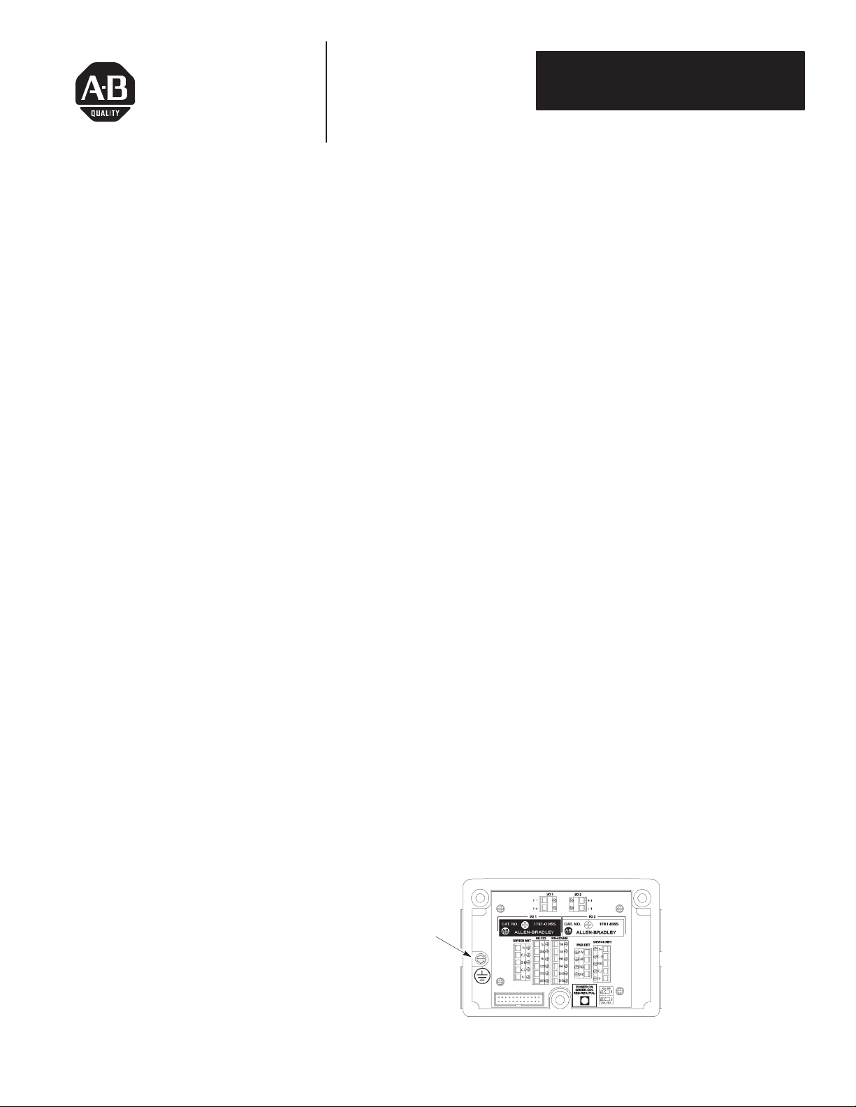
The wiring base contains all of the wiring connections for the AdaptaScan
Reader along with sockets for two I/O modules. Two versions of the
AdapataScan wiring base are available, a metric (Catalog No. 2755-NB41)
and U.S. version (Catalog No. 2755-NB40). Both versions of the wiring
base are identical except for the conduit openings and bottom mount thread
sizes.
Note: The three screws provided with the Catalog No. 2755-NB40 or
-NB41 wiring base are used with the mounting bracket kit (Catalog No.
2755-NM42).
Before mounting the wiring base, determine the proper orientation and
position as described in the AdaptaScan Reader user manual.
• Leave adequate clearances for wiring.
• Cover unused openings with conduit plugs (3 plugs provided with wiring
base). The wiring base has four conduit openings. Use Conduit fittings
with rubber grommets on cables that enter the wiring base. Two different
sized grommets (for conduit fittings) are provided with each Reader.
• Route wires carefully to reduce or minimize electrical noise. When
communication and power wiring must cross, make their intersection
perpendicular.
• Use proper grounding to limit the effects of noise due to Electromagnetic
Interference (EMI). To avoid problems caused by EMI, all cables must
be shielded and grounded at one end. Grounding is also an important
safety measure in electrical installations.
Connect to
Earth Ground
Wiring Base
Page 2
Instructions
ounting Dimensions
ounting t
irin
AdaptaScan Wiring Bases
Catalog Number 2755-NB40, -NB41
M
and Clearances
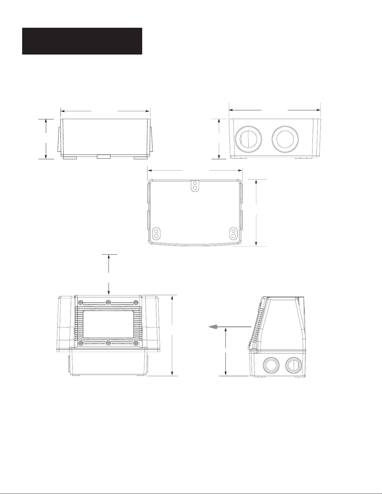
1.67 Inches
(42 mm)
5.36 Inches
(137 mm)
Wirng Base
Front View
The following shows the dimensions clearances for the wiring base and the
Reader/wiring base assembly.
3.87 Inches
(98 mm)
1.67 Inches
(42 mm)
5.36 Inches
(137 mm)
Wiring Base
Bottom View
Wiring Base
End View
3.87 Inches
(98 mm)
M
2
he W
Leave 1 inch (25.4 mm) Clearance for
Reader installation and viewing of LED indicators.
Front View
g Base
There are 2 options for mounting the wiring base (Catalog No. 2755-NB40
or -NB41):
• Top Mounting
Mount the base using mounting screws through the top mounting holes.
• Bottom Mounting
Mount the base using screws through the mounting surface into threaded
holes on the bottom of the wiring base.
5.82 Inches
(143 mm)
Midpoint of Scan Line
Variable
Side View
Page 3

Top Mounting Holes
4.46 Inches
(113 mm)
Worksheet
AdaptaScan Wiring Bases
Catalog No. 2755-NB40, -NB41
Top Mounting
The wiring base mounts from the top to any flat surface with three #10 or M5
mounting screws. The screw heads must be less than 3/8 inch in diameter
allowing them to fit inside the mounting hole. The length of the mounting
screws must be 1/2 inch (12.5 mm) plus the depth the screw penetrates the
mounting surface.
A full size mounting template (No. 40062–310–01) is provided with the
wiring base. Use the following diagram for reference.
3 Holes
2.79 Inches
(71 mm)
2.65 Inches
(67 mm)
4.46 Inches
(113 mm)
Scan Beam
Bottom Mounting
The wiring base mounts from the bottom to any flat surface with three
mounting screws. The holes on the U.S. version have #10-32 UNF-2B
threads. The holes on the metric version have M5 x .8 threads. The length
of the screws must not be greater than 1/2 inch (12.5 mm) plus the thickness
of the mounting surface.
A full size mounting template (No. 40062–310–01) is provided with the
wiring base. Use the following diagram for reference.
Wiring Base Has Three
Threaded Mountng Holes
2.79 Inches
(71 mm)
2.65 Inches
(67 mm)
Scan Beam
3 Holes
.6 inch (15 mm) deep
Thread Size of Holes
U.S.
#10-32 UNF-2B
Metric
M5 x .8
3
Page 4

Instructions
AdaptaScan Wiring Bases
Catalog Number 2755-NB40, -NB41
Hole Plugs
Three hole plugs are supplied with the wiring base. Use these plugs on
unused conduit openings to maintain the NEMA Type 4 rating.
• U.S. Wiring Base (Catalog No. 2755-NB40)
The conduit opening for the U.S. wiring base uses an N.P.S.C. threaded
plug. Use teflon tape or other thread sealant when inserting the hole plug
in the conduit opening to maintain a NEMA Type 4 seal. Tighten hole
plug with a 3/8” hex wrench.
• Metric Wiring Base (Catalog No. 2755-NB41)
The conduit opening for the metric version requires an O-ring with the
hole plug. Place the O-ring on the hole plug, then insert the hole plug in
the conduit opening and tighten with a flat blade screwdriver.
Wiring Base Dust Cover
To prevent debris from entering the wiring base when a Reader is not
installed, slip the wiring base dust cover over the base. The wiring base dust
cover is held in place by the stretch fit of the cover itself.
ATTENTION: The wiring base dust cover is not intended for
permanent installation. The wiring base dust cover temporarily
!
protects the wiring base until a Reader is installed.
4
Copyright 1995 Allen-Bradley Company, Inc. Printed in USA
40062–308–01(A)
 Loading...