

Page 1
PowerFlex® DC Drive and Stand-Alone Regulator (SAR)
Control Circuit Board
Installation Instructions
ATTENTION: Only qualified personnel familiar with DC drives
and associated machinery should plan or implement the installation,
start-up and subsequent maintenance of the system. Failure to
comply may result in personal injury and/or equipment damage.
ATTENTION: To avoid an electric shock hazard, ensure that all
power to the drive has been removed before performing the
following.
ATTENTION: This drive contains ESD (Electrostatic Discharge)
sensitive parts and assemblies. Static control precautions are required
when installing, testing, servicing or repairing this assembly.
Component damage may result if ESD control procedures are not
followed. If you are not familiar with static control procedures,
reference A-B publication 8000-4.5.2, “Guarding Against
Electrostatic Damage” or any other applicable ESD protection
handbook.
What This Kit Includes
What This Option Provides
Tools That You Need
• Control circuit board
• Five screws with captive lock washers
• Static strap
• Flathead screwdriver for terminal block connections
The Control circuit board is the main drive-mounted board that controls the
drive and provides these Input/Output (I/O) signals:
• Eight Digital Inputs
• Four Digital Outputs
• Three Analog Inputs
• Two Analog Outputs
• Digital Encoder Input
• DC Analog Tachometer Input
• Phillips® screwdriver
• Hexalobular screwdriver
• Flathead screwdriver
• Nut driver or wrench for hex stand-offs
®
Phillips
is a registered trademark of Phillips Screw Company.
Publication 20P-IN004B-EN-P
Page 2
2
What You Need to Do
Step 1: Save the Parameter Configuration
Step 2: Remove Power from the Drive
To install the Control board:
❐ Step 1: Save the Parameter Configuration
❐ Step 2: Remove Power from the Drive
❐ Step 3: Remove the Drive Covers
❐ Step 4: Remove the Communication Adapter and EMI Shield
❐ Step 5: Remove the Existing Connections and Option Board(s)
❐ Step 6: Remove the Existing Control Board
❐ Step 7: Install the New Control Board
❐ Step 8: Wire the Control Board
❐ Step 9: Document the Change
If possible, save the drive and adapter parameter configuration to a Human
Interface Module (HIM) Set or by up loading the drive and adapter parameters
to an offline database file using DriveExecutive™. Refer to the PowerF lex DC
Digital Drive User Manual, publication 20P-UM001
the HIM or the on-line Help provided with DriveExecutive.
ATTENTION: Remove power before making or breaking cable
connections. When you remove or insert a cable connector with
power applied, an electrical arc may occur. An electrical arc can
cause personal injury or property damage by:
, for information on using
• sending an erroneous signal to your system’s field devices,
causing unintended machine motion
• causing an explosion in a hazardous environment
Electrical arcing causes excessive wear to contacts on both the
module and its mating connector. Worn contacts may create electrical
resistance.
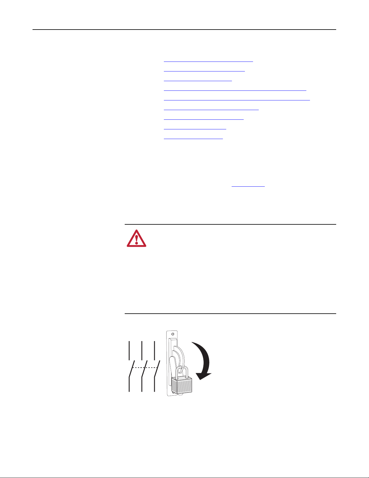
Remove and lock-out all incoming power to the drive.
L1 L2 L3
I
O
Publication 20P-IN004B-EN-P
Page 3
3
Step 3: Remove the Drive Covers
• To open frame A drives and the stand-alone regulator, see Frame A Drives
and the Stand-Alone Regulator below.
• To open frame B and C drives see Frame B and C Drives
• To open frame D drives see Frame D Drives
on page 5.
on page 4.
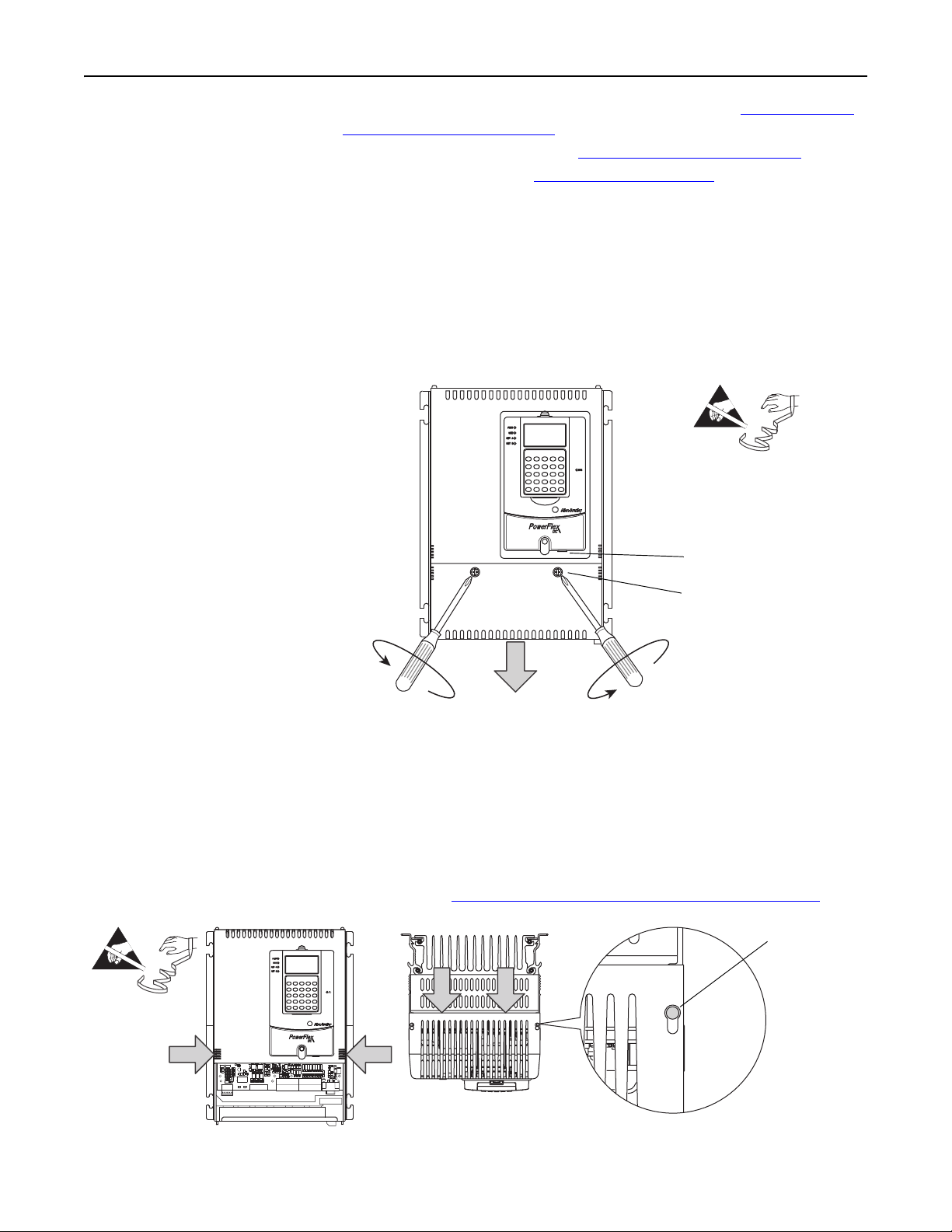
Frame A Drives and the Stand-Alone Regulator
1. Disconnect the Device Peripheral Interface (DPI) cable from the HIM
assembly (if present).
2. Loosen the captive screws that secure the bottom front cover to the drive,
then slide the cover down and off the drive chassis.
=
Disconnect DPI cable
Tightening torque:
1.5 N•m (13.3.lb•in)
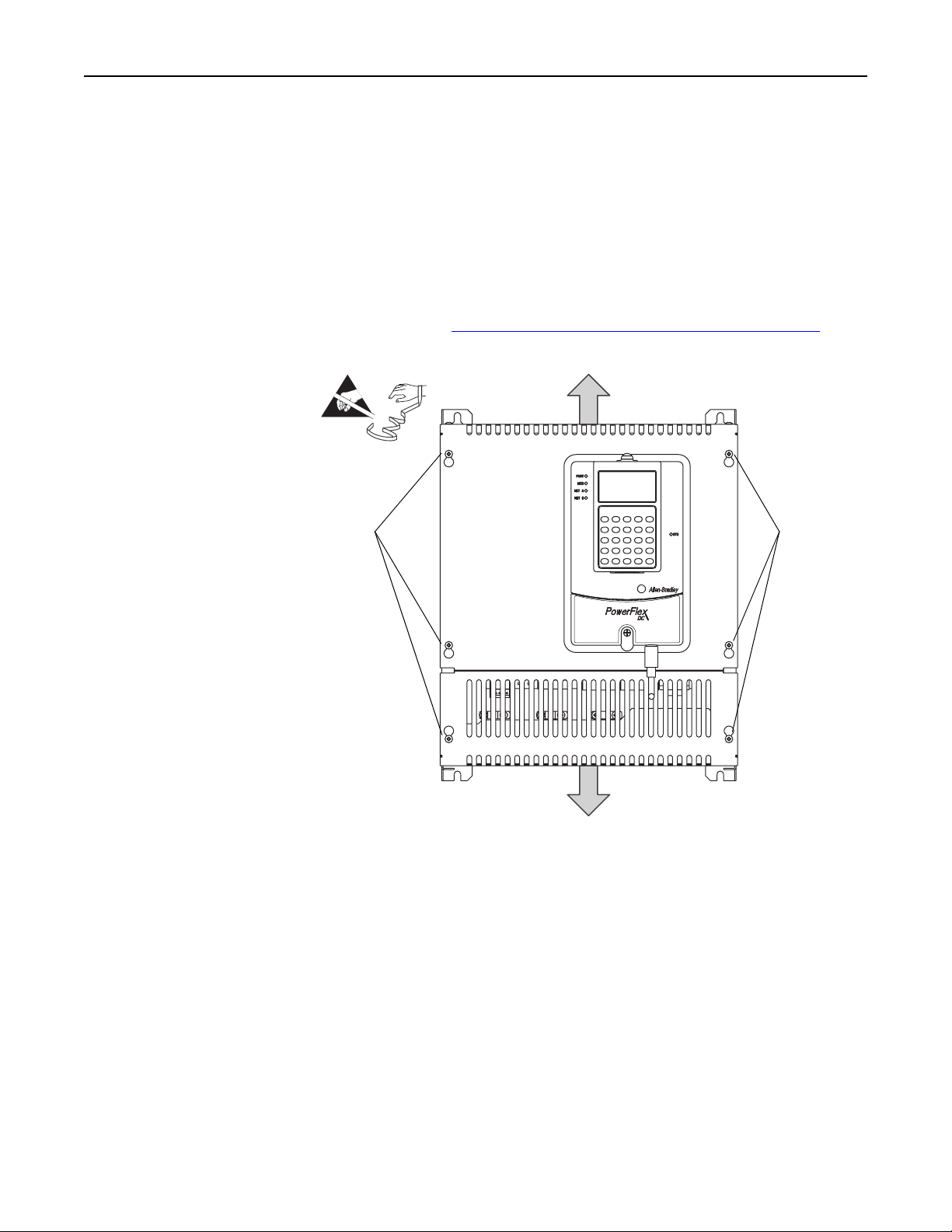
3. Press in on the sides at the bottom edge of the top cover and pull the cover
toward you until the cover is partially off the drive chassis. Then pull the top
of the cover toward you until the mounting pins align with the keyholes in
the top of the cover. Then carefully lift the cover off of the drive chassis.
Important: The HIM assembly is connected to the control board via a
communication cable. Carefully set the top cover down next
to the chassis.
4. Continue with Disconnect the HIM Communication Cable
=
on page 6.
When mounting
pins fits in
keyhole, lift
cover off drive
chassis.
Publication 20P-IN004B-EN-P
Page 4
4
Frame B and C Drives
1. Disconnect the DPI cable from the HIM (if present).
2. Loosen, but do not remove, the screws that secure the top and bottom front
covers to the drive, then slide the covers off the drive chassis.
Important: The HIM assembly is connected to the control board via a
communication cable. Carefully set the top cover down next
to the chassis.
3. Continue with Disconnect the HIM Communication Cable
=
Frames B shown
Loosen
screws
Disconnect
DPI cable.
on page 6.
Tightening torque:
1.5 N•m (13.3.lb•in)
Loosen
screws
Publication 20P-IN004B-EN-P
Page 5
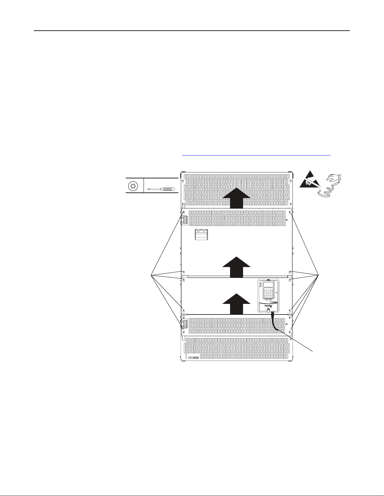
Frame D Drives
1. Disconnect the DPI cable from the HIM assembly (if present).
2. Loosen, but do not remove, the four hexalobular screws that secure each of
the three covers to the control pan on the drive, then slide the covers up and
off the drive chassis. Tightening torque is noted in the illustration for
reassembly.
Important: A communication cable connects the HIM assembly to the
control board mounted on the control pan. Therefore, the
middle control pan cover and HIM assembly cannot be fully
removed from the drive until the cable is disconnected.
5
3. Continue with Disconnect the HIM Communication Cable
T15
Tightening torque:
1.5 N•m (13 lb•in)
Loosen
screws
on page 6.
=
Loosen
screws
Disconnect
DPI cable
Publication 20P-IN004B-EN-P
Page 6
6
Disconnect the HIM Communication Cable
For all drives, disconnect the HIM communication cable from the connector on
the upper right corner of the control board and set the cover aside.
=
All Frames
(Frame A shown)
Pull tabs out
to disconnect
cable.
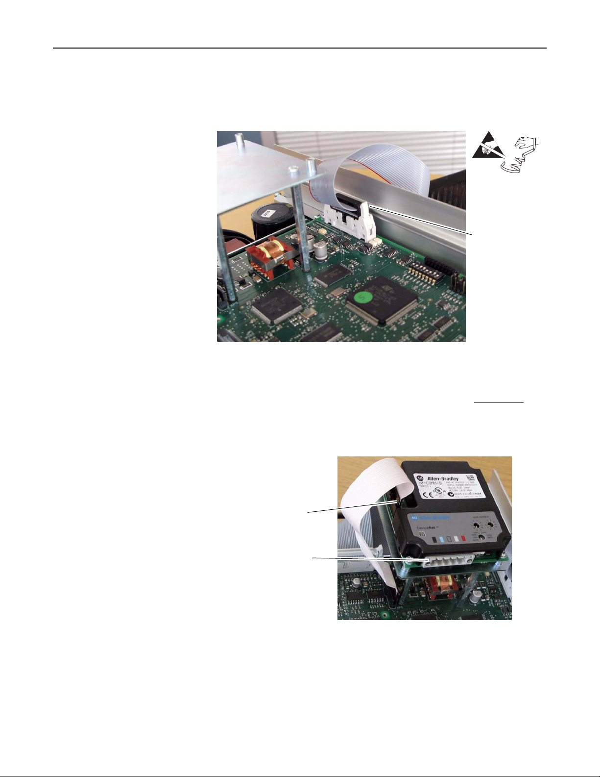
Step 4: Remove the Communication Adapter and EMI Shield
If a communication adapter is not installed, continue with step 4 on page 7.
1. Disconnect the interface cable from the adapter and set it aside.
2. Disconnect any network cables from the adapter and set them aside.
Disconnect interface cable
Disconnect network cables
Publication 20P-IN004B-EN-P
Page 7

3. Remove the four screws that secure the adapter to the EMI shield and
remove the adapter.
Remove four screws
Tightening torque:
0.9 N•m (8 lb•in)
4. Remove the three screws that secure the EMI shield to the stand-offs on the
control board and remove the EMI shield.
7
Remove three screws
Tightening torque:
1.0 N•m (8.9 lb•in)
5. Remove the three stand-offs from the control board.
Remove three standoffs
Tightening torque:
1.0 N•m (8.9 lb•in)
Publication 20P-IN004B-EN-P
Page 8

8
Step 5: Remove the Existing Connections and Option Board(s)
If the optional resolver feedback module, I/O expansion, and 115V AC to
24V DC converter boards are not installed on the control board, continue with
Step 6: Remove the Existing Control Board
on page 13.
Important:Mark all connections and wires before removing to avoid incorrect
wiring during reassembly.
Step 5A: Remove the Resolver Feedback Module
If the optional resolver feedback module is not installed, continue with Step 5B:
Remove the Optional I/O Expansion Board on page 10.
Important:The resolver feedback module can only be used with PowerFlex DC
drives with firmware version 5.002 or higher.
Important:The resolver feedback module consists of an interface board and a
feedback board. For this procedure, both boards of the resolver
feedback module are removed together, as an assembly.
1. Remove the three plug-in I/O terminal blocks from the resolver feedback
module assembly.
2. Remove the four mounting screws for the resolver interface board.
Resolver feedback board
Resolver interface board
=
Remove four screws
(resolver interface board)
Tightening torque is
0.7 N•m (6.2 lb•in)
Plug-in I/O terminal blocks
XR
XA
XP3
J1 J2
P4
S2
S4
P2 P3
XRE
P1
S21
TB1 TB2
P1
S15
XFCD
S1
Publication 20P-IN004B-EN-P
Page 9

3. Carefully lift the resolver interface module off of the control board, pulling
the stacker connector out of the XRE connectors on the control board.
Important: Lift the resolver interface board straight up so that the stacker
connector pins do not bend or break.
9
Resolver
interface board
XRE connector
Side view
Control board
Stacker
connector
XRE
connector
Resolver interface board
Capped pins
to right
Control board
Bottom view
4. Remove the four stand-offs and washers that support the resolver interface
board on the control board.
Publication 20P-IN004B-EN-P
Page 10

10
Step 5B: Remove the Optional I/O Expansion Board
If the optional I/O expansion board is not installed, continue with Step 5C:
Remove the 115V AC to 24V DC Converter Board on page 12.
1. Remove the plug-in I/O terminal blocks.
2. Remove the two screws that secure the board to the stand-offs on the control
board.
=
3. Carefully remove the I/O expansion board from the control board.
=
Pins connected to connector XBB
Lift board straight up
and off control board
Remove two screws
Tightening torque:
1.0 N•m (8.9 lb•in)
Important: Lift the board straight up so that the connector pins on the
I/O expansion board do not bend or break.
Publication 20P-IN004B-EN-P
Page 11

4. Remove the two stand-offs and washers that support the I/O expansion
board on the control board.
=
11
Remove two stand-offs
Tightening torque:
1.0 N•m (8.9 lb•in)
Publication 20P-IN004B-EN-P
Page 12

12
Step 5C: Remove the 115V AC to 24V DC Converter Board
If the optional 115V AC to 24V DC converter board is not installed, continue
with Step 6: Remove the Existing Control Board
1. Remove the plug-in I/O terminal blocks.
2. Remove the two screws that secure the I/O converter board to the stand-offs
on the control board and remove the converter board.
on page 13.
Remove two screws
Tightening torque:
1.0 N•m (8.9 lb•in)
3. Remove the two stand-offs and washers that support the converter board on
the control board.
Remove two stand-offs
Tightening torque:
1.0 N•m (8.9 lb•in)
Publication 20P-IN004B-EN-P
Page 13

13
Step 6: Remove the Existing Control Board
S14
S20
1 2 3 4 5 6 7 8
S4
S4
- A B C +
- A B C +
1. Record the DIP switch and jumper settings on the control board.
1 2 3 4 5 6 7 8
S14
ON
S20
ON
S10
21 22 23 24 25 26 27 28 29 30
21 22 23 24 25 26 27 28 29 30
1 2 3 4 5 6 7 8 9 10
1 2 3 4 5 6 7 8 9 10
31 32 33 34 35 36 37 38 39 40
31 32 33 34 35 36 37 38 39 40
11 12 13 14 15 16 17 18 19 20
11 12 13 14 15 16 17 18 19 20
DEBUG
S21
ENC_5 ENC_12
S11
S9
A+ A- B+ B- Z+ Z- COM +V
A+ A- B+ B- Z+ Z- COM +V
S15
1 2 3 4 5 6 7 8
RST
ACT
RUN
PWR
S15
S21
S9, S10, S11
Jumper/
Switch Function Setting
S4 Configures the input voltage of the DC analog tachometer.
S9 Configures the input signal of Analog Input 1 (terminals 1 and 2):
Note: The input signal type must also be programmed accordingly using parameter 71 [Anlg In1 Config].
S10 Configures the input signal of Analog Input 2 (terminal 3 and 4):
Note: The input signal type must also be programmed accordingly using parameter 76 [Anlg In2 Config].
S11 Configures the input signal of Analog Input 3 (terminals 5 and 6):
Note: The input signal type must also be programmed accordingly using parameter 81 [Anlg In3 Config].
S14 Field current resistors setting.
Important: In addition, the value selected with switch S14 must be entered in parameter 374 [Drv Fld Brdg Cur] in the
control software when the drive is commissioned.
S14-1 =
S14-2 =
S14-3 =
S14-4 =
S14-5 =
S14-6 =
S14-7 = (not used)
S14-8 = (not used)
S15 Configuration of the control circuit board to the appropriate drive size. This value is set to the appropriate size at the
factory.
S15-1 =
S15-2 =
S15-3 =
S15-4 =
S15-5 =
S15-6 =
S15-7 =
S15-8 =
S20 Monitoring of the Z channel of the digital encoder on connector XE2:
S21 Encoder power supply voltage and input adaptation selection:
Note: When control power is supplied to the drive, the appropriate LED lights to indicate the selection of the switch.
Publication 20P-IN004B-EN-P
Page 14

14
2. Carefully disconnect the cables from connectors XFCD, XA, and XR on the
control board.
3. Remove the plug-in I/O and control terminal blocks with the wiring kept in
place.
Disconnect
cables
=
Disconnect I/O
and control
wiring
Remove screws
Tightening torque:
1.0 N•m (8.9 lb•in)
4. Remove the five screws that secure the control board to the control EMI
shield and remove the board from the drive.
Publication 20P-IN004B-EN-P
Page 15

15
Step 7: Install the New Control Board
Step 8: Wire the Control Board
1. Install the new control board in the reverse order of removal as detailed in
Step 6: Remove the Existing Control Board
on page 13.
2. Verify that all DIP switch and jumper settings match those recorded in the
chart on page 13
publication 20P-UM001
. Refer to the PowerFlex DC Digital Drive User Manual,
, for detailed information on DIP switch and
jumper settings.
Install the I/O and control wiring in reverse order of removal.
Figure 1 I/O and Control Wire Routing
Route I/O and control
wiring between
bottom front cover
and power terminal
cover/shield.
(Frame A shown)
Publication 20P-IN004B-EN-P
Page 16

16
Step 9: Document the Change
1. Record the installation of the new control board and date of installation on
the field installed option label on the side of the drive (as shown below).
2. Replace the drive covers in the reverse order of removal as described in Step
3: Remove the Drive Covers
on page 3.
3. Install DPI cable (if present).
4. Down load the parameter configuration back into the drive.
Frame A Shown
Related Documentation
Publication 20P-IN004B-EN-P
Allen-Bradley publications are available on the internet at
www.rockwellautomation.com/literature
For . . . Read this document
In-depth information regarding the
operation of PowerFlex Digital DC drives
In-depth information regarding the
installation and wiring of the resolver
feedback option module
In-depth information regarding the
installation and wiring of the I/O
expansion circuit board
In-depth information regarding the
installation and wiring of the115V AC to
24V DC converter board
User Manual - PowerFlex Digital DC Drives 20P-UM001
Installation Instructions - PowerFlex DC
Drive Resolver Feedback Option Module
PowerFlex DC Drive Analog and Digital
I/O Expansion Circuit Board
PowerFlex DC Drive 115V AC to 24V DC
I/O Converter Circuit Board
.
Publication
Number
20P-IN071
20P-IN002
20P-IN003
Page 17

Notes:
17
Publication 20P-IN004B-EN-P
Page 18

1S7A42
U.S. Allen-Bradley Drives Technical Support - Tel: (1) 262.512.8176, Fax: (1) 262.512.2222, E-mail: support@drives.ra.rockwell.com, Online: www.ab.com/support/abdrives
www.rockwel lautomation.com
Power, Control and Information Solutions Headquarters
Americas: Rockwell Automation, 1201 South Second Street, Milwaukee, WI 53204-2496 USA, Tel: (1) 414.382.2000, Fax: (1) 414.382.4444
Europe/Middle East/Africa: Rockwell Automation NV, Pegasus Park, De Kleetlaan 12a, 1831 Diegem, Belgium, Tel: (32) 2 663 0600, Fax: (32) 2 663 0640
Asia Pacic: Rockwell Automation, Level 14, Core F, Cyberport 3, 100 Cyberport Road, Hong Kong, Tel: (852) 2887 4788, Fax: (852) 2508 1846
Publication 20P-IN004B-EN-P - June 2011
Supersedes 20P-IN004A-EN-P - October 2007 Copyright © 2011 Rockwell Automation. All rights reserved. Printed in U.S.A.
 Loading...