

Page 1
PowerFlex® DC Drive
Frame D AC Current Transducers
Installation Instructions
ATTENTION: Only qualified personnel familiar with DC drives
and associated machinery should plan or implement the installation,
start-up and subsequent maintenance of the system. Failure to comply
may result in personal injury and/or equipment damage.
ATTENTION: To avoid an electric shock hazard, ensure that all
power to the drive has been removed before performing the following.
ATTENTION: This drive contains ESD (Electrostatic Discharge)
sensitive parts and assemblies. Static control precautions are required
when installing, testing, servicing or repairing this assembly.
Component damage may result if ESD control procedures are not
followed. If you are not familiar with static control procedures,
reference A-B publication 8000-4.5.2, “Guarding Against
Electrostatic Damage” or any other applicable ESD protection
handbook.
What This Kit Includes
Tools That You Need
What You Need to Do
• Two AC current transducers
• Four mounting screws
• Static strap
• Hexalobular screwdriver
• Flathead screwdriver
• Torque wrench
To install the AC current transducers:
❐ Step 1: Remove power from the drive
❐ Step 2: Remove the protective covers and open the control panel
❐ Step 3: Remove the existing AC current transducers
❐ Step 4: Install the new AC current transducers
❐ Step 5: Close the control panel, replace the covers and document the
change
Publication 20P-IN059A-EN-P
Page 2
2
Step 1: Remove Power
from the Drive
ATTENTION: Remove power before making or breaking cable
connections. When you remove or insert a cable connector with
power applied, an electrical arc may occur. An electrical arc can
cause personal injury or property damage by:
• sending an erroneous signal to your system’s field devices,
causing unintended machine motion
• causing an explosion in a hazardous environment
Electrical arcing causes excessive wear to contacts on both the
module and its mating connector. Worn contacts may create electrical
resistance.
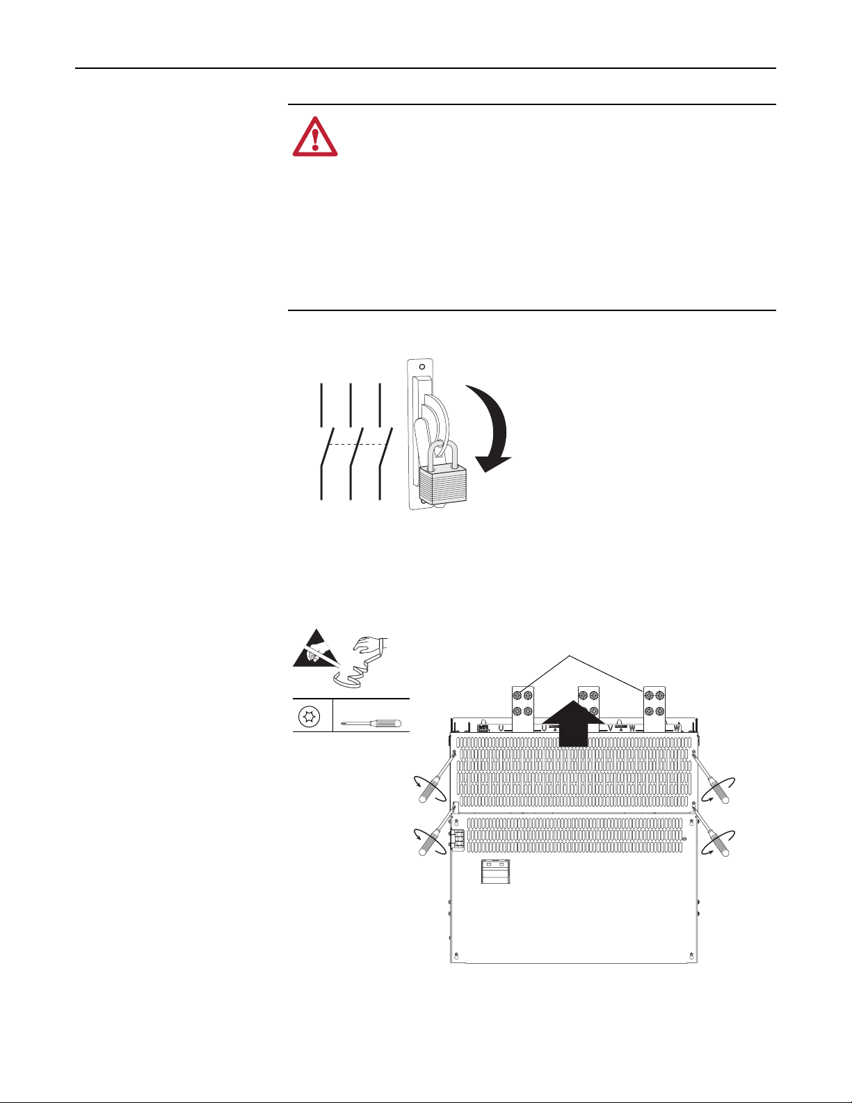
• Remove and lock-out all incoming power to the drive.
L1 L2 L3
I
O
Step 2: Remove the
Protective Covers and Open
the Control Panel
1. Loosen, but do not remove, the four hexalobular screws that secure the top
protective cover to the drive, then slide the cover up and off the drive
chassis. Tightening torque is noted in the illustration for reassembly.
AC current transducers located on
=
T15
Tightening torque:
1.5 N•m (13 lb•in)
U and W terminals behind cover
Publication 20P-IN059A-EN-P
Page 3
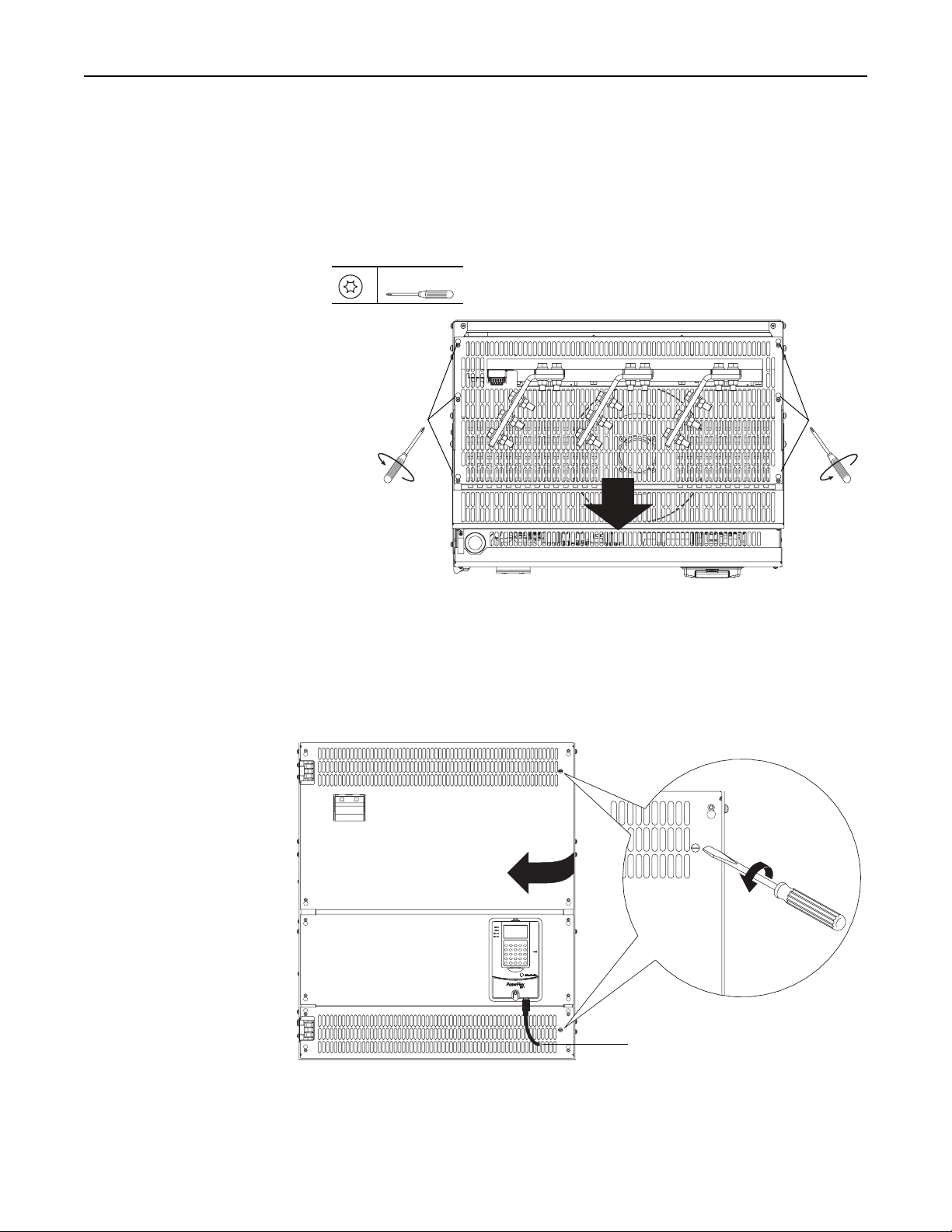
2. Loosen, but do not remove, the six hexalobular screws that secure the top air
flow plate to the drive, then slide the plate forward to lift it off the screws.
Tightening torque is noted in the illustration for reassembly.
Note: The air flow plate cannot be removed from the drive unless the AC
input wiring and bus bar extensions (if installed) are removed. However, the
plate must be removed to remove the AC input terminals below it.
3
T15
Tightening torque:
1.5 N•m (13 lb•in)
Loosen
screws
Top View of Drive
Loosen
screws
Pull plate forward to lift off screws
3. Disconnect the DPI cable from the HIM (if present).
4. Insert a flathead screwdriver into the holes in the right side of the protective
covers on the drive, turn the latch 90° counter-clockwise, and open the
control panel to the left.
Disconnect DPI cable
90°
Publication 20P-IN059A-EN-P
Page 4

4
Step 3: Remove the
Existing AC Current
Transducers
Important: Mark all connections and wires before removal to avoid
incorrect wiring during reassembly.
1. The U and W phase AC input terminal bus bars must be disconnected and
pulled up in order to remove the AC current transducers. Remove the wiring
from the U and W phase AC input terminal bus bars, if necessary.
2. Remove the four bolts and washers that secure the top insulator bar, over the
AC input terminal bus bars, to the drive frame and remove the insulator bar.
Disconnect wiring from
U and W phase AC
input terminal bus bars
Top insulator bar
XF XC
Remove bolts and
washers and
insulator bar
AC current
transducers
Publication 20P-IN059A-EN-P
Page 5

XF XC
5
3. Remove the bolt and washer that secures each of the U and W phase AC
input terminal bus bars to the rear insulator bar.
Remove bolt
and washer
4. Remove the two nuts and washers that secure the signal wires to the
terminals on each of the AC current transducers and remove the wires.
5. Loosen the two screws that secure each of the AC current transducers to the
U and W phase terminal bus bar. The current transducers will be loose on
the bus bars.
Remove nut, washer
and, signal wires
Loosen two
screws on CTs
Publication 20P-IN059A-EN-P
Page 6

6
6. Remove the four M12 bolts and washers that secure each of the U and W
phase AC input terminal bus bars to the input bus bars and carefully slide
the terminal bus bars up until the AC current transducers can be removed
from the bus bars.
Slide bus bars up until AC current
transducers can be removed
Step 4: Install the New AC
Current Transducers
W phase bus bar
Signal wireU phase bus bar
Remove bolts and
washers from U and
W phase bus bars
Install the new AC current transducers in reverse order of removal as detailed in
Step 3: Remove the Existing AC Current Transducers
above.
• Tightening torque for the M12 bolts is 45 N•m (398 lb•in).
• Verify that signal wire that was disconnected from the U and W phase bus
bars when removing the current transducers is re-installed.
Publication 20P-IN059A-EN-P
Page 7

7
Step 5: Close the Control
Panel, Replace the Covers
and Document the Change
1. Close the control panel and replace the top air flow plate and protective
cover in the order as described in Step 2: Remove the Protective Covers and
Open the Control Panel on page 2.
2. Record the installation of the new AC current transducers and date of
installation on the Field Installed Option label on the side of the drive (as
shown below).
Related Documentation
Allen-Bradley publications are available on the internet at
www.rockwellautomation.com/literature.
For . . . Read this document
In depth information regarding the
operation of PowerFlex Digital DC drives
User Manual - PowerFlex Digital DC Drives 20P-UM001…
Publication
Number
Publication 20P-IN059A-EN-P
Page 8

A
A
1S7A63
www.rockwellautomation.com
Power, Control and Information Solutions
mericas: Rockwell Automation, 1201 South Second Street, Milwaukee, WI 53204-2496 USA, Tel: (1) 414.382.2000,
Europe/Middle East/Africa:
sia Pacific: Rockwell Automation, Level 14, Core F, Cyberport 3, 100 Cyberport Road, Hong Kong, Tel: (852) 2887 4788, Fax: (852) 2508 1846
Rockwell Automation SA/NV, Vorstlaan/Boulevard du Souverain 36, 1170 Brussels, Belgium, Tel: (32) 2 663 0600, Fax: (32) 2 663 0640
Publication 20P-IN059A-EN-P - January 2011
Copyright © 2011 Rockwell Automation. All rights reserved. Printed in USA.
Fax: (1) 414.382.4444
 Loading...