

Page 1
Installation Instructions
!
d
Ultra1500 Battery
(Catalog Number 2090-DA-BAT)
This publication provides instructions for installing or replacing the 3.6V battery in an
Ultra1500
encoder to operate as an absolute multi-turn encoder.
Installing the Battery
The procedure varies slightly for a new installation versus maintenance or drive warnings:
Main and Control Power should be removed and software must be set when a battery is first
installed. Control Power should remain ON when a battery is replaced, but Main Power
should be removed (OFF).
Refer to Figure 1 to locate the battery compartment (BATT) on the Ultra1500 drive, and to
determine wire color and connector orientation to achieve proper polarity.
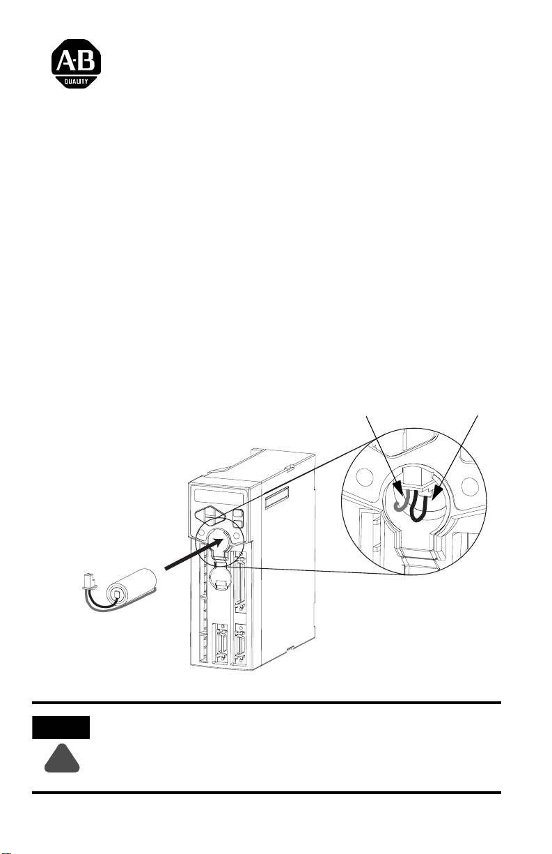
Figure 1 Ultra1500 Battery Orientation and Connection
®
servo drive. The battery allows a TL-Series motor equipped with an SA35 type
Battery connector is keyed:
Flat surface faces front of drive,
Rounded surfaces face inward.
ATTENTION
The 2090-DA-BAT is a non-rechargeable lithium battery, and unique storage and
transportation restrictions may apply.
If you are not familiar with current regulations, contact your local or state
environmental coordinator, the U.S. Department of Transportation (DOT), or the
U.S. Environmental Protection Agency (EPA).
Positive wire (red) on
left-side of connector.
When disconnecting the battery, pressure is
best applied to both sides of the connector.
A needle nose plier or similar tool can be use
to apply pressure.
Negative wire (black) on
right-side of connector.
Battery connector installed on
Ultra1500 drive
2092-IN001C-EN-P — July 2004
Page 2
To install a new battery, or replace an existing battery, perform the following steps:
!
1. For a new installation or if a battery low voltage fault has occurred, remove main and control AC
power from the drive. Otherwise, if this is a maintenance update or if a battery low voltage
warning has occurred, remove only the main AC power but retain the control AC power so that
the absolute position of the motor is not lost when the existing battery is disconnected.
ATTENTION
To avoid hazard of electrical shock, verify that all voltage on the DC bus
capacitors has been discharged before attempting to service, repair, or remove this
unit. This product connects to stored energy devices. You should only attempt the
procedures in this document if you are qualified to do so and familiar with
solid-state control equipment and the safety procedures in publication NFPA 70E.
2. Open the BATT compartment door. See Figure 1 for location. If the battery needs to be removed,
disconnect battery by carefully pulling downward on the connector. Slightly raise the BATT door
for clearance, and slide battery out of the drive.
Note: Pressure is best applied to both sides of the connector. A needle nose plier or similar tool
can be used to apply pressure.
3. Identify the polarity of the new battery and its connector as shown in Figure 1, and then slide the
battery into the drive.
4. Affix the connector as shown in Figure 1, and close the BATT compartment door.
5. If this is a new installation, make sure that the Encoder Backup Battery parameter is set to
INSTALLED (in the Encoders window [Ultra1500] of Ultraware
®
v1.60 or higher).
6. If this is a new installation or if a battery low voltage fault occurred, the axis must be homed to
establish the absolute reference position for motion.
For more information refer to our web site:
For Rockwell Automation Technical Support information refer to:
Allen-Bradley is a registered trademark of Rockwell Automation, Inc.
Ultra1500 and Ultraware are trademarks of Rockwell Automation, Inc.
www.ab.com/motion
www.ab.com/support
or Tel: (1) 440.646.5800
2092-IN001C-EN-P — July 2004
Supersedes Publication 2092-IN001B-EN-P July 2004 Copyright © 2005 Rockwell Automation, Inc. All rights reserved. Printed in the USA.
 Loading...