

Page 1
Installation Instructions
!
Resistive Brake Module
Unpacking Your Resistive Brake Module
(Catalog Numbers 2090-XB33-16, 2090-XB33-32,
2090-XB120-01, 2090-XB120-03, and 2090-XB120-06
This publication provides installation instructions for the
Allen-Bradley
instructions for mounting your RBM to the panel and wiring it to a drive
system. For installation and integration instructions specific to a drive
system, refer to Related Documentation on page 24.
Refer to the System Design for Control of Electrical Noise (publication
GMC-RM001x-EN-P) for greater detail on reducing electrical noise
when mounting your RBM.
There are no field replaceable components in an RBM.
Remove all packing material, wedges, and braces from within and
around the components. After unpacking, check the catalog number on
the item(s) nameplate against the purchase order.
Each RBM ships with:
• This installation sheet (publication 2090-IN009x-EN-P).
• One set of connectors for wiring the RBM to a drive:
• TB1 - Drive Connection
• TB2 - Motor Connection
• TB3 - I/O Connection
• TB4 - 230VAC Aux Power Connection (2090-XB120-xx only)
®
Bulletin 2090 Resistive Brake Module (RBM). Use these
Note: Power and I/O cables are not provided with the RBM. Refer to
Accessory Equipment on page 23 for catalog numbers of items
available from Rockwell Automation. I/O cables must be
supplied by the user.
ATTENTION
To avoid hazard of electrical shock, perform all
mounting and wiring prior to applying power to the
RBM or the drive system it connects to. Once power
is applied, connector terminals may have voltage
present even when not in use.
Publication 2090-IN009F-EN-P — November 2004
Page 2
2 Resistive Brake Module Installation Instructions
!
Important User Information
Because of the variety of uses for the products described in this publication,
those responsible for the application and use of this control equipment must
satisfy themselves that all necessary steps have been taken to assure that each
application and use meets all performance and safety requirements, including
any applicable laws, regulations, codes and standards.
The illustrations, charts, sample programs and layout examples shown in this
guide are intended solely for purposes of example. Since there are many
variables and requirements associated with any particular installation,
Allen-Bradley
intellectual property liability) for actual use based upon the examples shown in
this publication.
Allen-Bradley publication SGI-1.1, Safety Guidelines for the Application, Installation
and Maintenance of Solid-State Control (available from your local Allen-Bradley
office), describes some important differences between solid-state equipment
and electromechanical devices that should be taken into consideration when
applying products such as those described in this publication.
Reproduction of the contents of this copyrighted publication, in whole or part,
without written permission of Rockwell Automation, is prohibited.
Throughout this manual we use notes to make you aware of safety
considerations :
®
does not assume responsibility or liability (to include
ATTENTION
Attention statements help you to:
• identify a hazard
• avoid a hazard
• recognize the consequences
IMPORTANT
Identifies information about practices or circumstances
that can lead to personal injury or death, property damage
or economic loss.
Identifies information that is critical for successful
application and understanding of the product.
Publication 2090-IN009F-EN-P — November 2004
Page 3
Resistive Brake Module Installation Instructions 3
!
Understanding Your Resistive Brake Module
The RBM provides an alternative way to brake a drive system. It provides the
control system engineer with the opportunity to design safety controls into a
machine’s drive system that have two key features:
• Physically and electrically separate the drive power output from its
corresponding motor.
• Reduce the stopping time for a motor and its load should a failure occur to
the machine in which it is installed.
Drive commands are the preferred and quickest way to bring a drive system to
a controlled stop. The RBM provides a non-mechanical method for braking a
drive system, by draining motor energy through a resistive load that dissipates
the energy as waste heat.
The RBM can resistively brake a motor once per minute with the following
inertia mismatch:
Resistive Brake Module Inertia Mismatch
2090-XB33-16, 2090-XB33-32
2090-XB120-01, 2090-XB120-03, 2090-XB120-06
Refer to the Motion Control Selection Guide (publication GMC-SG001x-EN-P)
for details on applicable RBM and motor combinations.
15:1 inertia mismatch
A contactor in the RBM physically and electrically separates the motor leads
from the drive output, and provides status outputs to a customer designed
safety circuit. To maximize the stopping speed, braking resistors are sized to
match the motor and load for a specific axis of the drive system. The resistors
are placed across the phases and brake the motor by quickly dissipating the
energy stored there.
ATTENTION
Implementation of safety circuits and risk assessment is the
responsibility of the machine builder. Reference
international standards EN1050 and EN954 estimation and
safety performance categories. For more information refer
to Understanding the Machinery Directive (publication
SHB-900).
Publication 2090-IN009F-EN-P — November 2004
Page 4
4 Resistive Brake Module Installation Instructions
!
System Mounting Requirements
There are several things that you need to take into account when preparing to
mount the Resistive Brake Module:
IMPORTANT
• The panel on which you install your components must be a flat, rigid,
vertical surface that is not subject to shock, vibration, moisture, oil mist,
dust, or corrosive vapors.
• The RBM must be enclosed in a grounded conductive enclosure offering
protection as defined in standard EN 60529 (IEC 529) to IP55 such that it
is not accessible to an operator or unskilled person, in order to comply
with UL
requirements providing protection to IP66.
ATTENTION
Plan the installation of your system so that you can
perform all cutting, drilling, tapping, and welding with the
system removed from the enclosure. Because the system is
of the open type construction, be careful to keep any metal
debris from falling into it. Metal debris or other foreign
matter can become lodged in the circuitry, which can result
in damage to components.
®
and CE requirements. A NEMA 4X enclosure exceeds these
We recommend that all equipment and components of
a machine or process system have a common earth
ground point connected to their chassis.
A grounded system provides a ground path for short
circuit protection. Grounding your modules and panels
minimizes the shock hazard to personnel and damage
to equipment caused by short circuits, transient
overvoltages, and accidental connection of energized
conductors to the equipment chassis.
Publication 2090-IN009F-EN-P — November 2004
For CE grounding requirements, refer to the
appropriate drive system installation manual listed in
Related Documentation.
• The ambient temperature of the enclosure in which you install the RBM
must not exceed 50° C (122° F).
• You need to maintain minimum clearances (refer to Figure 2 and 3) for
proper airflow, easy module access, and proper cable bend radius.
• The RBM can operate at elevations to 1500 m (5000 ft) without derating,
however, the continuous current rating must be de-rated by 3% for each
additional 300 m (1000 ft) up to 3000 m (10,000 ft). Consult your local
Allen-Bradley representative prior to operating at over 3000 m (10,000 ft).
Refer to Specifications on page 19 for mounting dimensions, power dissipation,
and environmental specifications for the RBM.
Page 5
Resistive Brake Module Installation Instructions 5
Establishing Noise Zones
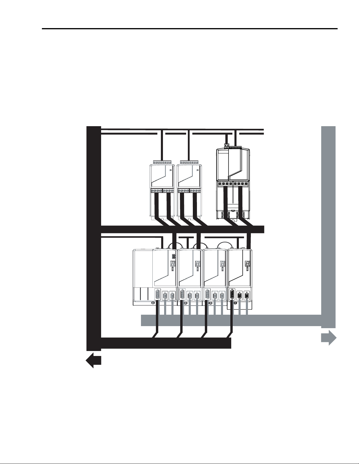
The figure below depicts noise zones for routing wiring. All wiring for the
RBM should be routed in a dirty zone. Refer to the appropriate drive system
installation manual listed in Related Documentation.
Figure 1
Noise Zones for Electrical Wiring
Dirty Wireway
Clean Wireway
Brake I/O Cables
230 VAC Power Cables
Resistive Brake Modules
One (1) 2090-XB120-xx
and
Two (2) 2090-XB33-xx
Power Cable
Shield Clamp
Motor Power Cables
Brake I/O Cables
Drive/System Modules
I/O and Feedback Cables
Route Encoder/Analog/Registration
Route 24V dc I/O
Shielded Cable
1 If system I/O cables contain dirty (relay, etc.) wires, route these signals with a separate cable in the dirty wireway.
1
Shielded Cable
Publication 2090-IN009F-EN-P — November 2004
Page 6
6 Resistive Brake Module Installation Instructions
Dimensions and Clearance Requirements
Mounting dimensions and clearance requirements for the 2090-XB33-xx are
shown in Figures 2 and 3, and for the 2090-XB120-xx in Figures 4 and 6.
IMPORTANT
The RBM must be mounted vertically, as shown, to ensure
proper contactor operation. The vertical mounting
tolerance is ±2°.
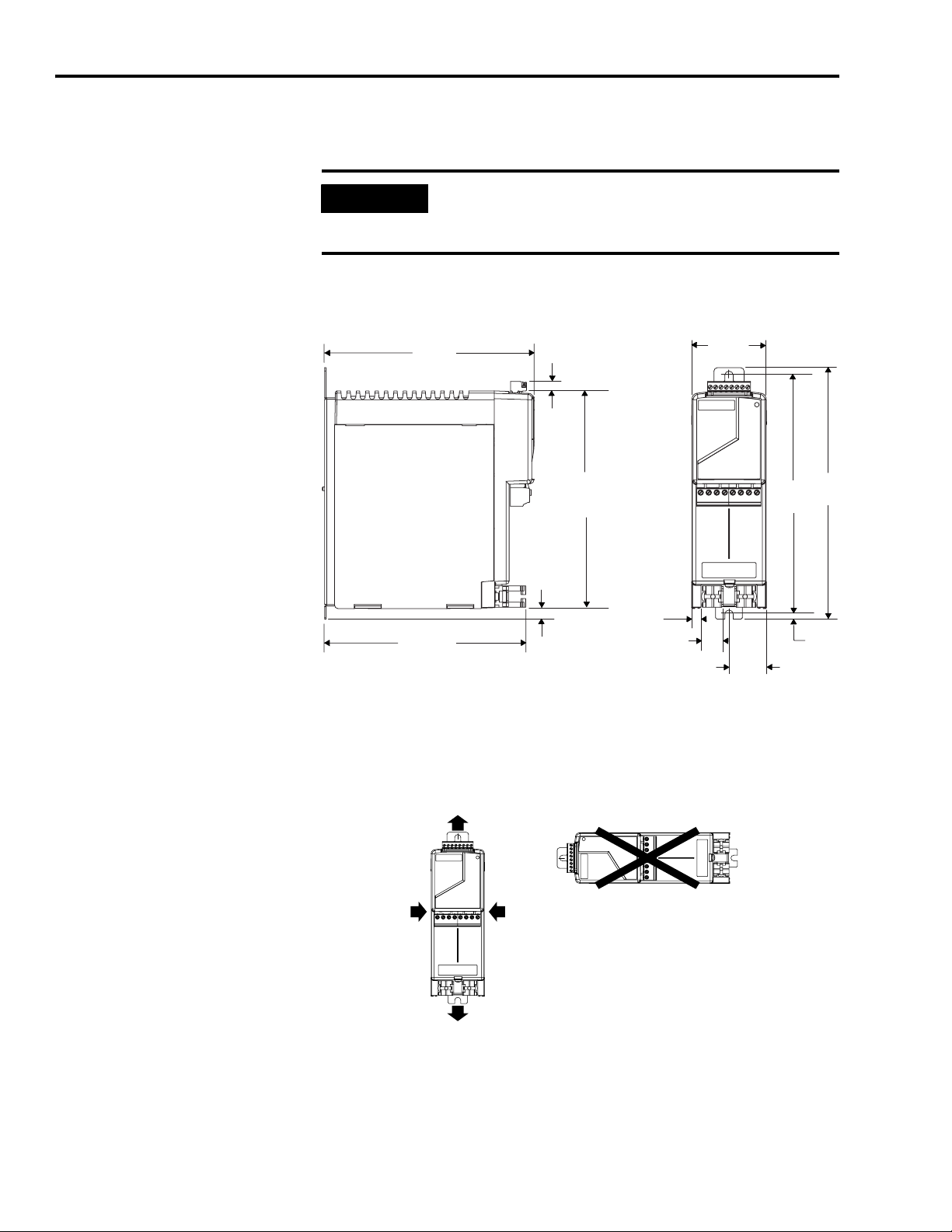
Figure 2
2090-XB33-xx Mounting Dimensions
198.6
(7.82)
6.1
(0.24)
205.4
(8.09)
11.7
(0.46)
70.0
(2.76)
226.5
(8.92)
238.3
(9.38)
190.6
(7.50)
Dimensions are in millimeters (inches).
Figure 3
2090-XB33-xx Minimum Clearance Requirements
50 mm (1.97 in.)
clearance for airflow
Clearance left
of RBM is not
required
50 mm (1.97 in.)
clearance for airflow
Clearance right
of RBM is not
required
10.0
(0.40)
20.0
(0.79)
35.0
(1.38)
4.6
(0.18)
Publication 2090-IN009F-EN-P — November 2004
Page 7
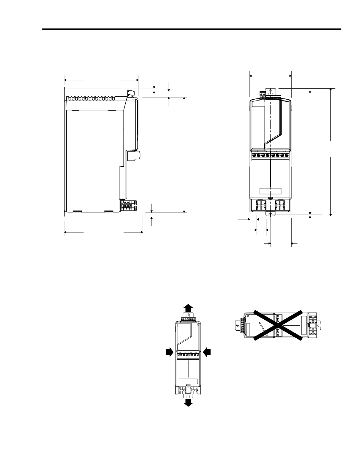
195.0
(7.68)
Resistive Brake Module Installation Instructions 7
Figure 4
2090-XB120-xx Mounting Dimensions
7.8
16.0
(0.31)
(0.63)
110.9
(4.37)
190.3
(7.49)
305.6
(12.03)
10.4
(0.41)
18.05
(0.71)
25.66
(1.01)
55.6
(2.19)
Dimensions are in millimeters (inches).
Figure 5
2090-XB120-xx Minimum Clearance Requirements
50 mm (1.97 in.)
clearance for airflow
328.17
(12.92)
339.8
(13.38)
4.57
(0.18)
Clearance left
of RBM is not
required
Clearance right
of RBM is not
required
50 mm (1.97 in.)
clearance for airflow
Publication 2090-IN009F-EN-P — November 2004
Page 8
8 Resistive Brake Module Installation Instructions
!
Installing Your Resistive Brake Module
These procedures assume you have prepared your panel and understand how
to bond the groundplane of your system.
ATTENTION
Refer to the System Design for Control of Electrical Noise Reference Manual
(publication GMC-RM001x-EN-P) for HF bonding techniques.
The RBM contains ESD (Electrostatic Discharge) sensitive
parts and assemblies. You are required to follow static
control precautions when you install, test, service, or repair
this assembly. If you do not follow ESD control
procedures, components can be damaged. If you are not
familiar with static control procedures, refer to
Allen-Bradley publication 8000-4.5.2, Guarding Against
Electrostatic Damage or any other applicable ESD Protection
Handbook.
Attaching Your Resistive Brake Module to the Panel
To mount your RBM:
1. Layout the position for your RBM in the enclosure.
IMPORTANT
Refer to the mounting dimensions and clearance requirements for each
type of RBM as listed below.
Dimensions for:
Mounting Figure 2 on page 6 Figure 4 on page 7
Clearance Figure 3 on page 6 Figure 5 on page 7
2. Attach the RBM to the cabinet. The recommended mounting hardware is
two M6 (1/4 in. - 20) bolts. A key-hole tab is at the top of the unit, and a
slotted mounting tab is at the bottom of the unit.
To improve EMC performance, mount the RBM on
the same panel as the drive system, and as close to the
drive as possible.
Typically the RBM should be positioned immediately
above the module it supports. Refer to Related
Documentation on page 24 for mounting instructions
and restrictions specific to a drive system, and
information on use with safety relays.
2090-XB33-xx 2090-XB120-xx
Publication 2090-IN009F-EN-P — November 2004
Page 9

Resistive Brake Module Installation Instructions 9
Ensure all fasteners are properly bonded to the subpanel. Refer to the
System Design for Control of Electrical Noise Reference Manual (publication
GMC-RM001x-EN-P) for HF bonding techniques.
Understanding RBM Connectors
IMPORTANT
To improve the bond between the RBM and subpanel,
construct your subpanel out of zinc plated (paint-free)
steel.
3. Tighten all mounting fasteners. The minimum recommended torque for
M6 (1/4 in. - 20) bolts is 1 Nm (9 in-lb).
RBMs have connectors and status indicators as listed in the following table:
RBM Connectors or Indicators
TB1 - Drive Connection X X
TB2 - Motor Connection X X
TB3 - I/O Connection X X
TB4 - 230VAC Aux Power Connection – X
Status LED X –
24 VDC Status LED – X
230 VAC Status LED – X
2090-XB33-xx 2090-XB120-xx
• Connectors and indicators locations are shown in Figure 6 on page 10 for
the 2090-XB33-xx, and Figure 7 on page 10 for the 2090-XB120-xx.
• Block diagrams of electrical functions are provided as Figure 8 on page 11
for the 2090-XB33-xx, and Figure 9 on page 12 for the 2090-XB120-xx.
• Connector functions for the 2090-XB33-xx, and the 2090-XB120-xx are
described in RBM Wiring Requirements on page 13.
Publication 2090-IN009F-EN-P — November 2004
Page 10

10 Resistive Brake Module Installation Instructions
Figure 6
2090-XB33-xx Resistive Brake Module Connectors and LED Indicator
Front view of 2090-XB33-xx Resistive
Brake Module
TB3 - I/O Connection
Status LED
TB1 - Drive Connection
TB2 - Motor Connection
TS_21
TS_22
CONSTAT_41
CONSTAT_42
SHIELD
COIL_A1
COIL_A2
SHIELD
Drive V-Phase
Drive U-Phase
Drive W-Phase
Power Cable
Shield Clamps (2)
Figure 7
2090-XB120-xx Resistive Brake Module Connectors and LED Indicators
Ground
Ground
Motor V-Phase
Motor U-Phase
Motor W-Phase
Front view 2090-XB120-xx Resistive
Brake Module
TB4 - 230VAC Aux Power Connection
TB3 - I/O Connection
24 VDC Status LED
230 VAC Status LED
TB1 - Drive Connection
TB2 - Motor Connection
TS_21
TS_22
CONSTAT_41
CONSTAT_42
SHIELD
COIL_A1
COIL_A2
230 VAC L1
230 VAC L2
SHIELD
Drive U-Phase
Power Cable
Shield Clamps (2)
Ground
Drive V-Phase
Drive W-Phase
Ground
Motor V-Phase
Motor U-Phase
Motor W-Phase
Publication 2090-IN009F-EN-P — November 2004
Page 11

Resistive Brake Module Installation Instructions 11
!
Wiring the RBM to a Drive System
This section provides wiring instructions for the Resistive Brake Module
within a general drive system. Refer to Related Documentation on page 24 for
installation and integration instructions containing wiring information specific
to a drive system. In addition:
ATTENTION
To comply with UL 508C, a Resistive Brake Module
must be protected upstream by a 2.5 kV overvoltage
control device.
Kinetix and Ultra servo drives from Rockwell
Automation meet this requirement. For additional
drive applicability, please consult your Allen-Bradley
representative.
• Figure 1 on page 5 depicts suggested routing of RBM wiring within the
dirty noise zone.
• Figure 6 and Figure 7 on page 10 show connector locations and provides
pinouts for each RBM connector.
• Recommended wire sizes and torque values for I/O signal wires and
power wires are provided in RBM Wiring Requirements on page 13 and in
Specifications.
TB1 - Drive
Connection
Ground
W Drive
V Drive
U Drive
Figure 8
2090-XB33-xx Resistive Brake Module Block Diagram
100S-C23
4
3
2
1
CR1
12
34
56
11 12
21 22
31 32
41 42
A1 A2
D1
Printed
Circuit
Board
4
3
2
1
1
2
3
4
5
6
7
8
TB2 - Motor
Connection
Ground
W Motor
V Motor
U Motor
Status LED
TB3 - I/O
TS_21
TS_22
CONSTAT_41
CONSTAT_42
SHIELD
COIL_A1
COIL_A2
SHIELD
T2 (Warning)T1 (Fault)
Publication 2090-IN009F-EN-P — November 2004
Page 12

12 Resistive Brake Module Installation Instructions
Figure 9
2090-XB120-xx Resistive Brake Module Block Diagram
TB1 - Drive
Connection
Ground
W Drive
V Drive
U Drive
TB2 - Motor
100S-C85
4
3
2
1
N/C
DC Interface Module
100-JE
A1
E1
E2
CR1
12
34
56
11 12
21 22
31 32
41 42
53 54
A1 A2
N/C
Printed
Circuit
Board
T1 (Fault)
Connection
4
Ground
3
W Motor
2
V Motor
1
U Motor
24VDC Status LED
230VAC Status LED
TB3 - I/O
1
TS_21
TS_22
2
3
CONSTAT_41
CONSTAT_42
4
SHIELD
5
COIL_A1
6
COIL_A2
7
SHIELD
8
TB4 - 230V ac
L1
T2 (Warning)
1
L2
2
Publication 2090-IN009F-EN-P — November 2004
Page 13

Resistive Brake Module Installation Instructions 13
RBM Wiring Requirements
Connector
Drive
Connection
Motor
Connection
Connects to:
Te rm i na l
-Pin
Signal
TB1-1 U Drive –
TB1-2 V Drive –
TB1-3 W Drive –
1
2
TB1-4
TB2-1 U Motor –
TB2-2 V Motor –
TB2-3 W Motor –
1
2
TB2-4
TB3-1
TS_21 In
Input/
Output
–
–
Description and Usage
230/460V power input from drive
230/460V power output to motor
RBM output with integral thermal
warning
Recommended
Wire Size 4
mm2 (AWG)
Minimum gauge
for power cable
is dependent on
the motor/drive
combination,
2090-XB33-xx
6 (10) maximum
2090-XB120-xx:
25 (3) maximum
Insulation Strip
Length
mm (in.)
2090-XB33-xx
10.0
(0.375)
2090-XB120-xx:
16.0
(0.63)
2090-XB33-xx
10.0
(0.375)
2090-XB120-xx:
16.0
(0.63)
Torq u e Va l ue
Nm (lb-in.)
2090-XB33-xx:
0.5 - 0.6
(4.4 - 5.3)
2090-XB120-xx:
2.5 - 2.9
(22.1 - 25.7)
2090-XB33-xx:
0.5 - 0.6
(4.4 - 5.3)
2090-XB120-xx:
2.5 - 2.9
(22.1 - 25.7)
Customer use of this auxiliary
contact may include:
TB3-2 TS_22 Out
• PLC or control string input that
RBM is nearing its thermal
limit
TB3-3 CONSTAT_41 In RBM output of a normally closed
contact
(Closed = motor disconnected
from drive)
Customer use of this auxiliary
contact may include:
TB3-4 CONSTAT_42 Out
• PLC input connection,
indicating RBM contactor
status
I/O Signals
5,6
• Safety relay input for safety
string
• Part of RBM safety string for
1.5 - 0.08
(16 - 28)
6.0
(0.25)
0.22 - 0.25
(1.9 - 2.2)
mechanical redundancy
TB3-5 SHIELD
3
–
I/O Shield internally terminated at
chassis ground
TB3-6 COIL_A1 In RBM contactor coil with integral
thermal fault. Applying 24V Coil
Power picks-up the contactor,
which connects drive power to
motor leads (i.e., motor rotates).
TB3-7 COIL_A2 Out
Customer use may include:
• Control from a safety relay
output or signal relay output
indicating system is clear for
rotation
TB3-8 SHIELD
230V Power
(2090-XB120-x
x only)
1 Connectors are keyed to prevent misconnection of power interface cables to and from the RBM.
2 Ground connection for the motor cable passes through the drive and motor connectors.
Cable shielding must be grounded to the chassis via the spring-loaded cable clamps.
3 I/O Shield terminations are connected internally to chassis ground.
4 Wire supplied by user should be stranded copper with 75° C (167° F) minimum rating. An earth ground connection is required for safe and proper operation. Local agency
rules apply.
5 For additional contactor applications, refer to the Allen-Bradley Safety Product Catalog (Publication S114-CA001A-EN-P).
6 I/O is powered by an external 24V (22.4 - 26.4), 0.5A power supply.
7 Provided by an external 230V (207 - 253), 1A power supply.
7
TB4-1 L1 – Auxiliary power input from
TB4-2 L2 –
3
–
I/O Shield internally terminated at
chassis ground
external 230 VAC power source
(2090-XB120-xx only)
4.0 - 0.2
(10 - 24)
7.0
(0.28)
0.5 - 0.6
(4.4 - 5.3)
Publication 2090-IN009F-EN-P — November 2004
Page 14

14 Resistive Brake Module Installation Instructions
!
Wiring Instructions
1. Allow five minutes for the power supplies to completely discharge before
proceeding.
ATTENTION
2. Separate the I/O signal cable and the power cables as shown in Figure 1
on page 5 and described below:
• I/O signal connections are at the top of the RBM (TB3).
• Power cable connections enter (TB1) and exit (TB2) at the bottom of
the RBM.
• Auxiliary power connections (2090-XB120-xx only) are at the top of
the RBM (TB4)
IMPORTANT
To avoid hazard of electrical shock, verify that all
voltage on the capacitors has been discharged before
attempting to service, repair, or remove this unit. This
product connects to stored energy devices. You should
only attempt the procedures in this document if you are
qualified to do so and familiar with solid-state control
equipment and the safety procedures in publication
NFPA 70E.
To ensure correct wiring, verify connector orientation
on the RBM before wiring each connector. Figure 6
and Figure 7 on page 10 show connector locations and
pinouts.
Publication 2090-IN009F-EN-P — November 2004
3. Prepare your I/O signal wires by stripping the appropriate length of
insulation from the end of the wire. Use caution not to nick, cut, or
otherwise damage strands as you remove the insulation.
Insert the wires into the TB3 terminal and torque the screws to the
specified value. Gently pull on the wire to make sure it does not come out
of its terminal. Re-insert and test any loose wires.
Strip this length of
If RBM is:
2090-XB33-xx 6.0 mm (0.25 in.)
2090-XB120-xx 7.0 mm (0.28 in.)
insulation from the I/O
wire:
Torque TB3 terminal screw
within this range:
0.22 - 0.25 Nm (1.9 - 2.2 in-lbs)
Page 15

Resistive Brake Module Installation Instructions 15
4. Prepare your power cables as shown in Figure 10. by stripping the
appropriate length of insulation from the end of the wire. Use caution not
to nick, cut, or otherwise damage strands as you remove the insulation.
Insert the wires into the proper terminal (TB1 or TB2) and torque the
screws. Gently pull on the wire to make sure it does not come out of its
terminal. Re-insert and test any loose wires.
Outer Insulation
Power Cable
Exposed Braid
46 mm (1.8 in.)
If RBM is:
Strip this length of
insulation from the
Torque TB1 or TB2 terminal
screw within this range:
power wire:
2090-XB33-xx 10.0 mm (0.375 in.) 0.5 - 0.6 Nm (4.4 - 5.3 lbs-in.)
2090-XB120-xx 16.0 mm (0.63 in.) 2.5 - 2.9 Nm (22.1 - 25.7 lbs-in.)
Figure 10
Shielded Power Cable Preparation
2090-XB33-xx Strip Length 10 mm (0.375 in.)
2090-XB120-xx Strip Length 16 mm (0.63 in.)
3
1
2
3
2090-XB33-xx: 76 mm (3.0 in.)
2090-XB120-xx: 119 mm (4.7 in.)
2090-XB33-xx: 122 mm (4.8 in.)
2090-XB120-xx: 165 mm (6.5 in.)
Motor Power Wires
5. Prepare your 230VAC auxiliary power cables (2090-XB120-xx only) by
stripping the appropriate length of insulation from the end of the wire.
Use caution not to nick, cut, or otherwise damage strands as you remove
the insulation.
Insert the wires into the TB4 terminal and torque the screws to the
specified value. Pull on each wire to ensure it is secured to the terminal.
Re-insert and test any loose wires.
Strip this length of
If RBM is:
2090-XB33-xx This terminal is not present
2090-XB120-xx 7.0 mm (0.28 in.) 0.5 - 0.6 Nm (4.4 to 5.3 lbs-in.)
insulation from the I/O
signal wire:
Torque TB4 terminal screws
within this range:
Publication 2090-IN009F-EN-P — November 2004
Page 16

16 Resistive Brake Module Installation Instructions
Applying the Power Cable Shield Clamp
To apply your power cable shield clamp:
1. Use a small flat blade screwdriver to depress the spring loaded clamping
plate as shown in Figure 11.
Figure 11
Depressing the Spring Clamp
Flat Blade Screwdriver
3.5 mm (0.14 in.) tip
Cable Clamp
Screwdriver
tip in slot
2. Position the exposed portion of the cable braid directly in line with the
clamp.
3. Release the spring, making sure the cable and cable braid are held secure
by the clamp.
4. Attach tie wrap around cable and clamp, if additional strain relief is
required (refer to Figure 12).
Figure 12
Motor Cable and Clamp
Exposed Braid
(under clamp)
Cable Clamp
Tie Wrap
Publication 2090-IN009F-EN-P — November 2004
Outer Insulation
Motor
Cable
Page 17

Resistive Brake Module Installation Instructions 17
Troubleshooting
There are no field replaceable components in an RBM. If problems persist
after attempting to troubleshoot the system, contact your Allen-Bradley
representative for further assistance.
24 VDC Status LED
The Status LED is ON when 24V is applied between COIL_A1 and
COIL_A2 (e.g., a Brake Enable signal is received from a drive).
Use the table below for troubleshooting the RBM using the 24 VDC Status
LED.
If 24 VDC Status LED is: RBM Contactor Status is: Potential Cause is: Possible Resolution is:
Steady Green
Blinking Green
(audible clicking)
Off
(intended)
Off
(unintended)
Contactor engaged – direct connection
between drive and motor
Contactor disengaged – no connection
between drive and motor
Contactor rapidly engaging/disengaging
Contactor disengaged
(connection open between drive and
motor)
No faults or failures N/A
Contactor failure
Recommended grounding not
followed
Control circuit improperly wired Verify control wiring and programming
No faults or failures N/A
+24V not applied between COIL_A1
and COIL_A2
T1 (Fault) thermostat open
Verify by monitoring CONSTAT_41/42
status (output is NC)
Contact AB representative
• Verify grounding
• Route wires away from noise sources
• Refer to GMC-RM001x-EN-P
• +24V supply is off
•Verify wiring
• Drive not enabled
• Contact AB representative
Duty cycle: exceeded; allow RBM to
cool.
Publication 2090-IN009F-EN-P — November 2004
Page 18

18 Resistive Brake Module Installation Instructions
230 VAC Auxiliary Power Status LED (2090-XB120-xx RBM only)
The 230 VAC Status LED is ON when 230V AC is applied to L1 and L2
(TB4) and the contactor is engaged by applying 24V DC across COIL_A1 and
COIL_A2 (e.g., a Brake Enable signal is received from a drive).
Use the table below for troubleshooting the RBM using the 230 VAC Status
LED. ‘1
If 230 VAC Status LED is: RBM Contactor Status is: Potential Cause is: Possible Resolution is:
Engaged No faults or failures N/A
Steady Green
Blinking Green
(audible clicking)
Off
(intended)
Off
(unintended)
Disengaged Contactor failure
Grounding
Rapidly engaging/disengaging
Engaged
Disengaged No faults or failures N/A
Engaged
Disengaged
230VAC is varying
Control circuit improperly wired Verify control wiring and programming
Contactor failure
(contacts welded together)
Contactor failure
(contacts welded together)
LED failure
+24V signal not functioning properly See other Troubleshooting tables
Contactor failure (coil damaged) Contact A-B representative
No 230V signal
Verify by monitoring CONSTAT_41/42
Contact AB representative
• Verify grounding
• Re-route wires
• Refer to GMC-RM001x-EN-P
• Check VAC Loading
• Check VAC Source
•Verify wiring
Verify by monitoring CONSTAT_41/42
Contact AB representative
Verify by monitoring CONSTAT_41/42
Contact AB representative
Verify by monitoring CONSTAT_41/42
Contact AB representative
•Verify wiring
• Verify 230VAC source
Publication 2090-IN009F-EN-P — November 2004
Page 19

Resistive Brake Module Installation Instructions 19
General Troubleshooting
Use the table below for troubleshooting motor faults that may result from the
RBM on a specific axis.
Condition: Potential Cause is: Possible Resolution is:
Specifications
No Rotation
(drive faults)
No Rotation
(no fault action)
Specifications for the Resistive Brake Module are provided below.
Catalog No.
2090-XB33-16 230 or 460 16
2090-XB33-32 230 or 460 32
2090-XB120-01 230 or 460 1
2090-XB120-06 230 or 460 6
Improper timing Adjust delay times of brake output signals
Improper wiring Verify wiring
Improper wiring Verify wiring
RBM contactor disengaged
(connection open between dr ive
and motor)
RBM contactor engaged
(direct connection between
drive and motor)
Drive
Voltage
Volts Ohms Joules Amps
Power Specifications (per phase):
Resistance
1
• +24V supply is off
• Verify wiring
• Drive not enabled
• Duty cycle: exceeded; allow RBM to cool.
• Contact AB representative
• Verify wiring
• Contact AB representative
Peak Energy Peak Drive Current
2 Amps
0-pk
150 33 23 30
290 106 75 45 2090-XB120-03 230 or 460 3
Continuous
Power
Watts
rms
1 Tolerance = +10%, - 10%
2 0-pk refers to peak of sine wave
Publication 2090-IN009F-EN-P — November 2004
Page 20

20 Resistive Brake Module Installation Instructions
Environmental Specifications Value
Vibration
• operating
Shock
• operating 15g, 11 msec half sine
Altitude 1500 m (5000 ft)
Humidity 5% to 95% non-condensing
Storage temperature
Ambient operating temperature
• minimum
• maximum
Air flow clearance
• above and below
• left and right
Temperature limits
• T1 (Fault)
• T2 (Warning output)
Duty cycle:
• 2090-XB33-16
• 2090-XB33-32
• 2090-XB120-01
• 2090-XB120-03
• 2090-XB120-06
1Power performance increases about 5.5W for every 1°C (3.1W/°F) drop in ambient temperature.
2 Refer to the Motion Control Selection Guide (publication GMC-SG001x-EN-P) for proper sizing.
1
Complete stop with
15:1 inertia mismatch
0.35 mm (0.014 in.) max.
displacement at 5-53 Hz
2g max. acceleration at
53 to 500 Hz
-25° C
70° C
0° C
50° C
50 mm
0 mm
80°±5° C
65°± 5° C
2
60 per hour, or 2
once per minute
(-13° F)
(158° F)
(32° F)
(122° F)
(1.97 in.)
(0 in.)
(176±9° F)
(119°±9 ° F)
Connectors
Ty pe
2090-XB33-xx
Drive Connection (TB1) 4-position plugable
Phoenix-type
Motor Connection (TB2) 0.5 - 0.6 (4.4 - 5.3)
I/O Terminals (TB3)
1
(7.62mm spacing)
8-position plugable
Phoenix-type
(5.08mm spacing)
2090-XB120-xx
Drive Connection (TB1) 4-position plugable
42 Series Molex
Motor Connection (TB2) 2.5 - 2.9 (22.1 - 25.7)
(12mm spacing)
8-position plugable
I/O Terminals (TB3)
Phoenix-type
(5.08mm spacing)
2-position plugable
230V Power Terminals (TB4)
Phoenix-type
(7.62mm spacing)
To rqu e
Nm (lbs-in.)
0.5 - 0.6 (4.4 - 5.3)
0.22 - 0.25 (1.9 - 2.2)
2.5 - 2.9 (22.1 - 25.7)
0.22 - 0.25 (1.9 - 2.2)
0.5 - 0.6 (4.4 - 5.3)
Publication 2090-IN009F-EN-P — November 2004
Page 21

Resistive Brake Module Installation Instructions 21
Wiring Requirements
Material Stranded copper
2090-XB33-xx
TB1 - Drive Connection and
TB2 - Motor Connection
TB3 - I/O
maximum 1
minimum 1
maximum
minimum
6 mm2
–
1.5 mm2
0.08 mm2
(10 AWG)
–
(16 AWG)
(28 AWG)
2090-XB120-xx
TB1 - Drive Connection and
TB2 - Motor Connection
maximum
minimum 1
1
25.0 mm2
2.50 mm2
(3 AWG)
(14 AWG)
TB3 - I/O
TB4 - 230V Input
maximum
minimum
maximum
minimum
1.50 mm2
0.08 mm2
4.0 mm2
0.20 mm2
(16 AWG)
(28 AWG)
(10 AWG)
(24 AWG)
Voltage
Drive, Motor, and 230V Aux 600V
I/O 250V
Temperature (per UL)
• preferred
• manufacturer minimum
• field wiring minimum
2
105° C
90° C
75° C
(221° F)
(194° F)
(167° F)
Maximum Length
•TB1 - Drive
• TB2 - Motor
• TB3 - I/O
• TB4 - 230V Input
1 Specific gauge of motor power cable depends on motor/drive combination.
2 Separate UL standards exist for manufactured and field wiring. Installation must comply with
local regulations.
3 If this product is installed within the European Union or EEC regions and requires the CE mark or
is installed in Australia and New Zealand and requires C-tick marking, refer to Related
Documentation on page 24 for installation and integration instructions defining total length
restrictions on a system level.
See system level
requirements for power
cable length restrictions.
N/A for I/O.
3
Mechanical Specifications Value
Mounting
• Hex cap screws
• Torque
1
metric (english)
minimum
M6
1 Nm
(1/4 in. - 20)
(9 in-lb)
Mounting position Vertical, within ±2°
Product Outline
2090-XB33-xx
• Height
• Depth
•Width
238.3 mm
198.6 mm
70.0 mm
(9.38 in.)
(7.82 in.)
(2.76 in.)
2090-XB120-xx
• Height
• Depth
•Width
339 mm
195 mm
110 mm
(13.38 in.)
(7.68 in.)
(4.37 in.)
Publication 2090-IN009F-EN-P — November 2004
Page 22

22 Resistive Brake Module Installation Instructions
Mechanical Specifications Value
Clearances 2
• Top
•Side
•Bottom
Weight
• 2090-XB33-16
• 2090-XB33-32
• 2090-XB120-01
• 2090-XB120-03
• 2090-XB120-06
1 Additional dimensional information is provided in Figure 2 on page 6.
2 Combustible material adjacent to the brake module may require additional restrictions
Safety Contactor Specifications - Allen-Bradley 100S Series
The information in this section is adapted from the Allen-Bradley Safety Product
Catalog (Publication S114-CA001x-EN-P). That document should be referred
to for the most recent information on the 100S Series Contactors.
50 mm
0 mm
50 mm
1.91 Kg (4.22 lbs)
2.75 Kg (6.06 lbs)
(i.e., Clearance based on ambient temperature of the brake module within the application).
(1.97 in.)
(0 in.)
(1.97 in.)
24V Coil Power
Specifications
Pickup 19.2 to 26.4 9.2 40 to 70
Dropout 2.4 to 14.6 0 17 to 23
Hold-In 14.6 to 26.4 9.2 N/A
I
e
[A] kW (50 Hz) HP (60 Hz)
AC-3 AC-1 230V 380V, 415V, 400V 500V 690V
23 32 7.5 11 11 11 2 3 5 7.5 15 15
I
e
[A] kW (50 Hz) HP (60 Hz)
Ratings for Switching AC Motors - AC-2, AC-3, AC-4
230V Coil Power
Specifications
Pickup 195.5 to 253.0 200/110 20.0 to 40.0
Dropout 69.0 to 138.0 0 10.0 to 60.0
Hold-In 138.0 to 253.0 16/4.5 N/A
Ratings for Switching AC Motors - AC-2, AC-3, AC-4
Voltage Range
Vdc
Voltage Range
Vac
Coil Consumption
Watts
∅ 3∅
1
115V 230V 200V 230V 460V 575V
Coil Consumption
VA/W
Operating Time
milliseconds
Operating Time
milliseconds
AC-3 AC-1 230V 380V, 415V, 400V 500V 690V
85 100 25 45 45 45 7.5 15 25 30 60 60
Publication 2090-IN009F-EN-P — November 2004
1
∅ 3∅
115V 230V 200V 230V 460V 575V
Page 23

Resistive Brake Module Installation Instructions 23
Auxiliary Contact Specifications
Auxiliary Contacts in Contactor Catalog Number 100-S 1
Current Switching
AC-1Ith
AC-15 at Rated Operating Voltage
DC-13 at Rated Operating g Voltage
Short-Circuit Protection
gG Fuse
Type 2 Coordination
Rated Impulse Voltage U
Insulation Voltage
(between control and load circuit DIN,VDE 0106,Part 101
(NAMUR recommendation)
Positively Guided Contacts
kV n/a
imp
at 40° C
(104° F)
at 60° C
(10°0 F)
V n/a
A10
A 6
V 24 48 120 240 400 500 600 690
A666321.51.20,7
V 2448125220440
A 3 1.5 0.6 0.3 0.2
A n/a
Between auxiliary contacts: 250 V
V
Between load and direct-connected aux. circuits:
690 V
Yes,
NO and NC mutually unrestricted, including N.C. in
relation to N.O.
1 Information adapted from the Allen-Bradley Safety Product Catalog (Publication S114-CA001A-EN-P), page 53.
Accessory Equipment
The cables provide an interface between the Resistive Brake Module and drive
power terminals. Refer to RBM Wiring Requirements on page 13 for pin,
description, and signal information about the connector kit.
Description Catalog Number
®
6000 Drive Interface Cable, Resistive Brake - 14 AWG, 66cm 2090-XXNRB-14F0P7
Kinetix
Kinetix 6000 Drive Interface Cable, Resistive Brake - 4, 8, or 10 AWG 2090-XXNRB-aFxxPyy
Ultra™ Drive Interface Cable, Resistive Brake - 14 AWG, 132cm 2090-XXNRB-14F1P3
Ultra Drive Interface Cable, Resistive Brake - 6, 8 or 10 AWG 2090-XXNRB-aFxxPyy
Connector Kit, Resistive Brake, 33A (TB1, TB2, TB3 Connectors) 2090-XNRBM-1
Connector Kit, Resistive Brake, 106A (TB1, TB2, TB3, TB4 Connectors) 2090-XNRBM-2
1 Where a = wire gauge in AWG.
2Where xx = cable length in full meters, and yy = length in decimeters.
1, 2
1,2
Publication 2090-IN009F-EN-P — November 2004
Page 24

Related Documentation
These publications provide additional information concerning related
Allen-Bradley products. To order printed copies, contact your Allen-Bradley
Distributor. To view and download, go to Literature Library at
http://www.rockwellautomation.com/literature.
For Information About Read This Document Publication Number
Installing, wiring, and troubleshooting a Kinetix 6000 drive Kinetix 6000 Installation Manual 2094-IN001x-EN-P
Configuring a Kinetix 6000 drive and system Kinetix 6000 Integration Manual 2094-IN002x-EN-P
Programming a motion application using Logix Logix Controller Motion Instruction Set Reference Manual 1756-RM007x-EN-P
ControlLogix™ motion and application examples ControlLogix Motion Module Programming Manual 1756-RM086x-EN-P
Configuring and troubleshooting ControlLogix motion modules
Minimizing and controlling system-level noise System Design for Control of Electrical Noise GMC-RM001x-EN-P
Sizing and configuring an application
Servo drives, motor, and accessories, including general technical
specifications
Information about international standards EN1050 and EN954
estimation and safety performance categories.
ControlLogix Motion Module Setup and Configuration
Manual
Motion Book Servo Sizing CD
(v4.0 or above)
1756-UM006x-EN-P
Motion Book-mmmyy
Motion Control Selection Guide GMC-SG001x-EN-P
Understanding the Machinery Directive SHB-900
For more information refer to our web site: www.ab.com/motion
For Allen-Bradley Technical Support information refer to: www.ab.com/support or Tel: (1) 440.646.5800
Allen-Bradley, A-B, and Kinetix are registered trademarks of Rockwell Automation.
ControlLogix, Ultra3000, and Ultra5000 are trademarks of Rockwell Automation.
Windows is a registered trademark of Microsoft Corporation.
UL is a registered trademark of Underwriters Laboratories, Inc.
Publication 2090-IN009F-EN-P — November 2004 319232-P06
Supersedes Publication 2090-IN009E-EN-P Copyright © 2004 Rockwell Automation. All rights reserved. Printed in USA.
 Loading...