

Page 1
Installation Instructions
o
Motor Feedback Breakout Board
Catalog Number 2090-UXBB-DM15
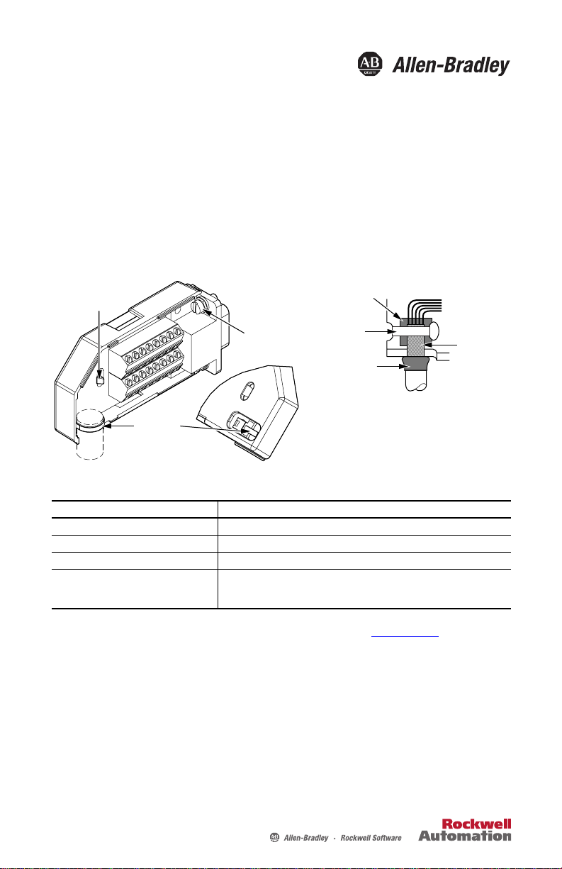
Install the Motor Feedback Breakout Board
Position cable shield against
Locking Tab
Cable Tie
this termination pad.
Mounting Screws (2)
2 x 4-40 UNC
Shrink-wrapped
Insulation
Follow these steps to form a compact connection.
1. Push the insulation down-and-over itself.
2. Move the insulation so it butts against the
outside wall of cover.
3. Tape or shrink-wrap the end of the insulation t
the cable.
Cable
Tie
Cable
Shield
Attribute 2090-UXBB-DM15
Cable diameter 11.4 mm (0.45 in.) max
Screw terminal wire size 0.06…1.31 mm
Recommended wire strip length 25…51 mm (1…2 in.)
Recommended torque
Mounting screw
Terminal screw
0.40 N•m (3.5 lb•in)
0.25 N•m (2.2 lb•in)
2
(30…16 AWG)
Refer to the Kinetix Motion Control Selection Guide, publication GMC-SG001, for
information about the compatability of the breakout board with your drive.
Page 2
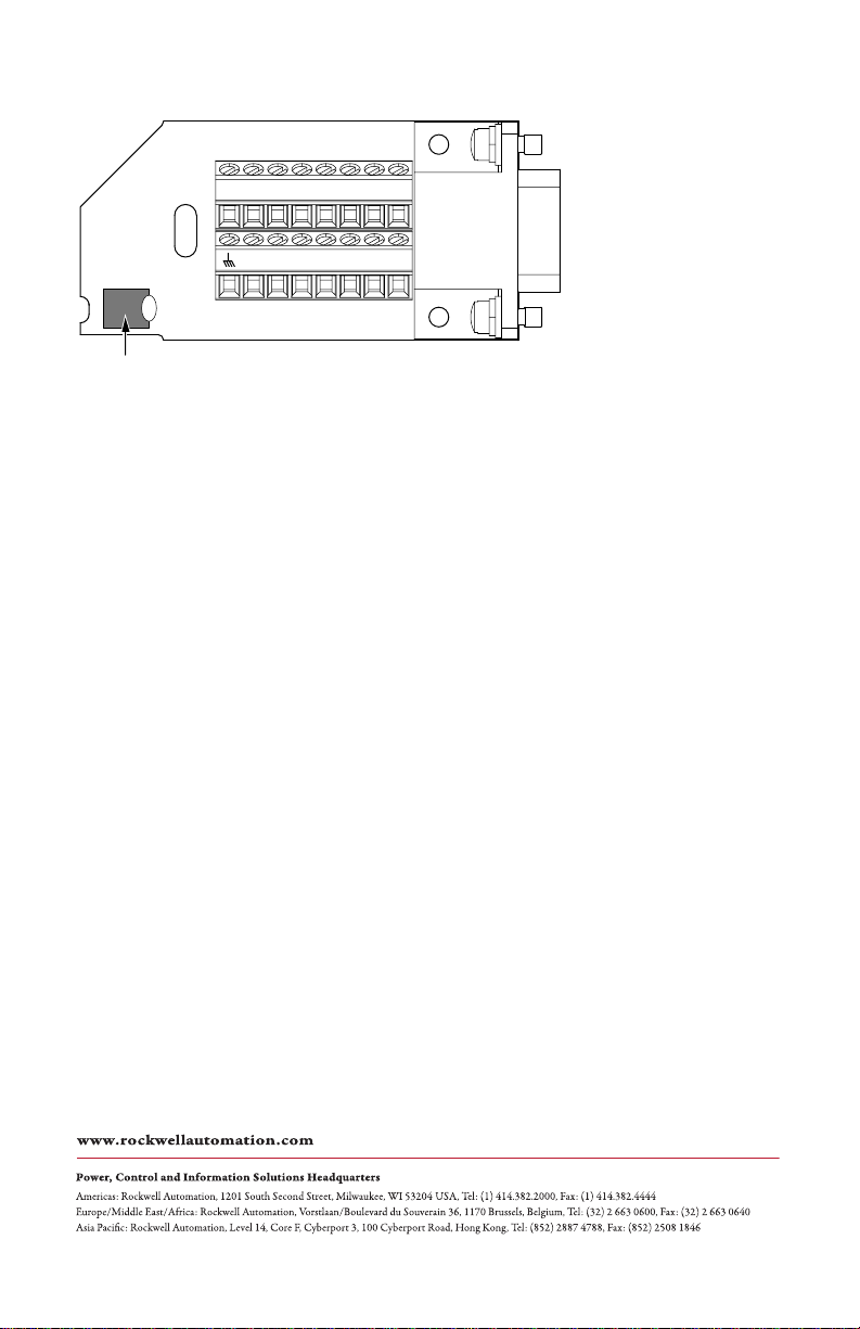
Connector Data
12345678
9101112131415
Cable Shield Termination Pad
Refer to your drive user manual for information on wiring the breakout board.
Allen-Bradley, Rockwell Automation, and Rockwell Software are trademarks of Rockwell Automation, Inc.
Trademarks not belonging to Rockwell Automation are property of their respective companies.
Rockwell Otomasyon Ticaret A.Ş., Kar Plaza İş Merkezi E Blok Kat:6 34752 İçerenköy, İstanbul, Tel: +90 (216) 5698400
Rockwell Automation Publication 2090-IN006B-EN-P - August 2010 PN-78225
Supersedes Publication 2090-IN006A-EN-P - August 2002 Copyright © 2010 Rockwell Automation, Inc. All rights reserved. Printed in the U.S.A.
 Loading...