

Page 1
Installation Instructions
900 Watt Passive Shunt Module
Ultra Series drives and controllers can require external power
dissipation when large inertial loads are present. To ensure that drive
faults due to excessive bus voltage do not occur, loads requiring
power dissipation that exceed a drive’s internal shunt capability
require the use of external shunt resistor(s).
The passive shunt (Catalog No. 1398-SR9PF or 2090-UCSR-P900) can
be used with the following products:
Drive Catalog No.
ULTRA 200 Drives 1398-DDM-075, -075X, -150, and -150X
ULTRA Plus Drives 1398-PDM-075 and 1398-PDM-150B
Ultra3000 Drives 2098-DSD-075, -075-SE, -075-DN, -075X, -075X-DN, -150,
-150-SE, -150-DN, -150X, and -150X-DN
Ultra5000 Drives 2098-IPD-075, -075-DN, -150, and -150-DN
ATTENTION
Using the passive shunt with modules not listed can
cause equipment damage or personal injury.
!
As a motor decelerates, power is returned from the motor to the drive
module, causing the bus voltage on the drive to increase. Ultra servo
amplifier products have circuitry that senses the voltage on the drive’s
DC bus and dissipates power when needed. When the bus voltage
reaches the shunt turn-on voltage of the drive, the internal shunt
circuitry allows the excessive regenerated power to be dissipated
through an external resistor. After the bus voltage is reduced to the
turn-off voltage level, the shunt transistor turns-off and no additional
power is dissipated by the shunt resistor.
1 Publication 2090-IN001A-EN-P — March 2001
Page 2
2 900 Watt Passive Shunt Module
Installing the Shunt
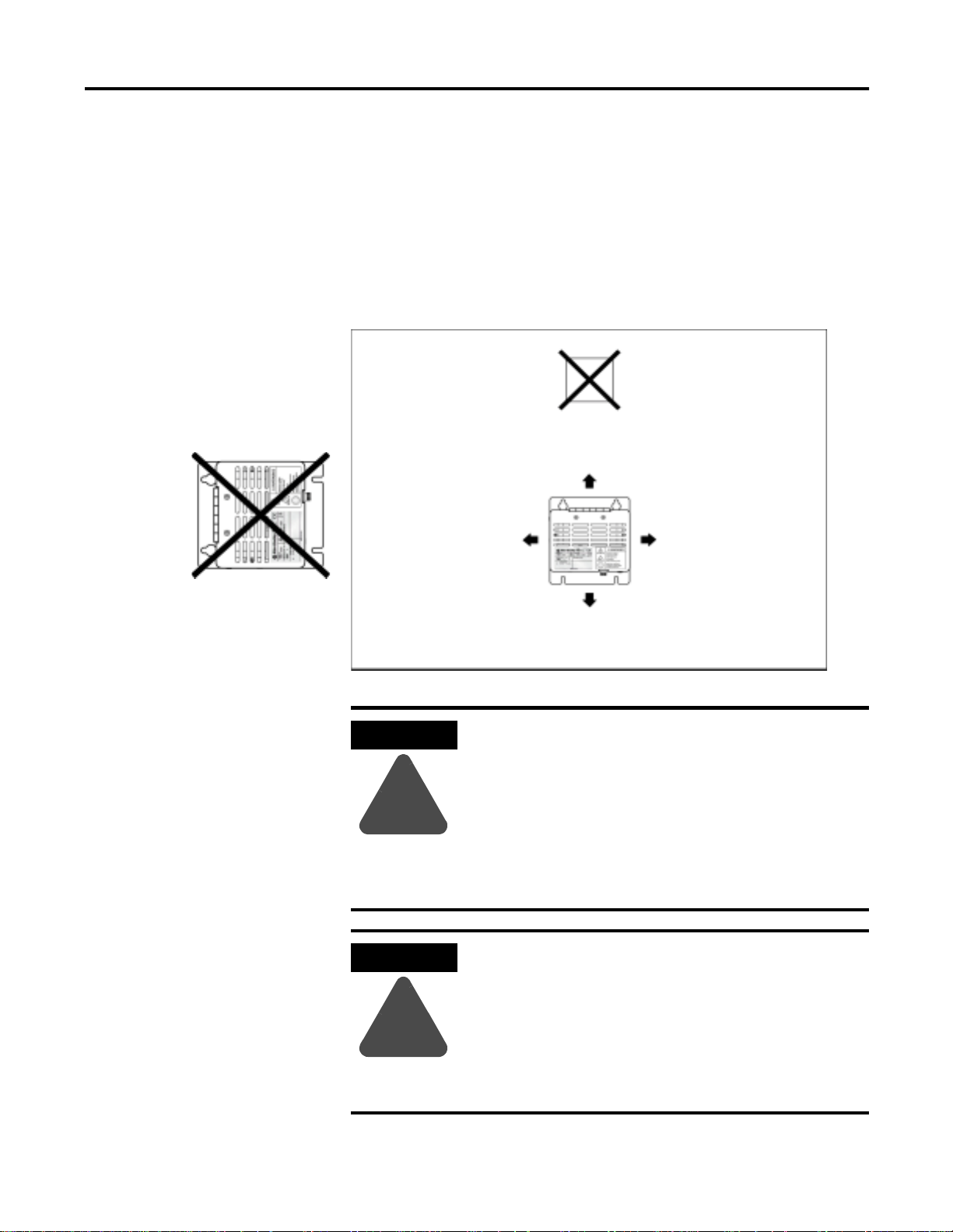
Do not mount shunt module
on its side
Orientation and Clearance
The following enclosure restrictions must be considered because the
shunt module dissipates excess regenerative power in the form of
heat. Refer to Figure 1 on page 2 and Figure 4 on page 9 for shunt
module spacing requirements.
Figure 1 Shunt Module Spacing Requirements Within an Enclosure
Do not mount temperature
sensitive components above
shunt module
155 mm (6.1 in.) min. of clearance
above the shunt module.
155 mm (6.1 in.) min. of
clearance on each side of the
shunt module.
155 mm (6.1 in.) min. of
clearance on each side of the
shunt module.
ATTENTION
!
ATTENTION
!
155 mm (6.1 in.) min. of clearance
below the shunt module
The shunt module can release a large amount of heat
over time.
Any materials above the shunt module or its
enclosure may need the protection of a metal plate
to keep from deteriorating.
Failure to observe this precaution could result in
damage to surrounding materials, possibly leading to
fire.
The shunt module can release a large amount of heat
inside an enclosure.
Ensure there is enough ventilation so as the
maximum ambient temperature of 50° C (122° F) is
not exceeded.
Failure to observe this precaution could result in
damage to the shunt module.
Publication 2090-IN001A-EN-P — March 2001
Page 3
900 Watt Passive Shunt Module 3
If the work environment dictates, mount the shunt module in an
enclosure providing protection against dust and splashing water
(IP54), or dust free and protected against water jets (IP65).
ATTENTION
!
Many NEMA (National Electrical Manufacturers Association) Type 4
cabinets provide this level of protection.
ATTENTION
Avoid contaminating electronic components.
Provide a quality air source to cabinets; free of
debris, oil, corrosives, or electrically conductive
contaminates. All cabinets should have scheduled
inspections and be cleaned as needed.
Failure to observe these safety procedures could
result in breakdown and damage to equipment.
If you mount the shunt module inside a cabinet, you
must make sure that the ambient temperature inside
the cabinet does not exceed 50° C (122° F).
!
Publication 2090-IN001A-EN-P — March 2001
Page 4

4 900 Watt Passive Shunt Module
900 Watt Continuous Dissipation Cabinet Layout
Figure 2 details the proper position and cable separation for mounting
a single shunt module with a one drive inside a cabinet.
Motor power cable
IMPORTANT
Only one passive shunt module can be used per
DDM/PDM/DSD-075, IPD-075 or damage to the
drive will result.
Figure 2 Typical Shunt Module Position and Conductor Routing for 900W Continuous Dissipation
AC power cable
155 mm (6.1 in.) of minimum clearance on all
sides of the shunt module
Always separate low voltage signal
wiring from high voltage power wiring to
reduce affects of EMI
Twist conductors (2 twists per foot min.)
Publication 2090-IN001A-EN-P — March 2001
Shielded metal conduit, shielded cable,
and ferrite filters are also recommended
for reducing the effects of EMI
When shielding is used, the shield must
be grounded to the shunt and drive as is
the motor power cable
Low voltage communications, Control I/O, and
Motor feedback cables
Page 5

900 Watt Passive Shunt Module 5
1,800 Watt Continuous Dissipation Cabinet Layout
Figure 3 details the proper position and cable separation for mounting
two shunt modules with one drive inside a cabinet. Two 900W shunt
modules are connected in a parallel, which doubles, to a total of
1,800W, the amount of continuous power dissipation on the DC bus.
Motor power cables
IMPORTANT
No more than two passive shunt modules can be
used per DDM/DSD/IPD-150, PDM-150B or damage
to the drive will result.
Figure 3 Typical Shunt Module Position and Conductor Routing for 1,800W Continuous Dissipation
AC power cables
155 mm (6.1 in.) of minimum clearance
on all sides of the shunt module
Twist conductors
Shielded metal
conduit, shielded
cable, and ferrite
filters are also
recommended for
reducing the effects
of EMI
(2 twists per foot min.)
Always separate low
voltage signal wiring
from high voltage
power wiring to reduce
affects of EMI
When shielding is used, the
shield must be grounded to the
shunt and drive as is the motor
power cable
Publication 2090-IN001A-EN-P — March 2001
Page 6

6 900 Watt Passive Shunt Module
Securing the Passive Shunt Module
The following procedure assumes you have prepared your mounting
panel. To mount your passive shunt module:
1. Install the top two mounting fasteners on the sub panel for the
shunt module. Refer to Product Specifications on page 8 for
specifications.
2. Mount the shunt module on the two fasteners.
3. Install the lower fasteners.
4. Tighten all mounting fasteners.
Wiring the Passive Shunt Module to a Drive
It is recommended to use shielded, high temperature (75° C, 600V),
8.4 mm
should be 3.05m (10 ft) with the shield grounded at both ends.
Unshielded wiring should be kept as short as possible.
Three recommended methods for wiring to reduce EMI noise can be
used to connect the passive shunt module with your drive.
You can use twisted conductors (2 twists per foot minimum) with
ferrite filters, shielded twisted cable, or shielded metal conduit.
When shielding is used, the shield must be grounded to the shunt and
drive chassis as is the motor power cable.
2
(8 AWG) copper wire. The maximum length of each wire
Publication 2090-IN001A-EN-P — March 2001
Page 7

900 Watt Passive Shunt Module 7
Connecting to the Shunt Terminal Block
1. Locate the external shunt terminal block (TB2) on your drive.
2.
Ensure there is no power applied to the drive.
3. Remove the jumper installed between terminals 1 and 2 of TB2.
4. Connect the lead wires to terminals 1 and 3 of TB2. Tighten screws
to 1.25 Nm (11 in-lbs).
5. Gently pull on each wire to make sure it does not release from its
terminal.
6. Re-insert and tighten any loose wires.
7. Open the front door of the passive shunt.
Insert wires
8. Connect the lead wires to terminal block inside front cover.
Polarity is not important. Tighten screws to 2.25 Nm (20 in-lb).
9. Close and secure cover of shunt module.
Publication 2090-IN001A-EN-P — March 2001
Page 8

8 900 Watt Passive Shunt Module
Product Specifications
Specifications for the passive shunt module are provided in the
following tables. Physical measurements are shown in Figure 4 on
page 9.
General Specifications Description
Weight net 3.31 kg (7 lbs)
Resistance
Power rating peak 10 kW
Fuse 10 Amp, 700 VDC, fast acting
Environmental Conditions Value
Vibration 2g at 10 to 2000 Hz
Shock 15g 11 msec half sine
Altitude 1500 m (5000 ft)
Humidity 5% to 95% non-condensing
Ambient operating temperature
shipping 4.08 kg (9 lbs)
18
Ω ± 10%
continuous 900 W
(Bussmann FWP10A14F)
1
0° to 50° C (32° to 122° F)
Air flow clearances 155 mm (6.1 in.) on all sides for air flow.
1
Power performance increases about 5.5 W for every 1°C (3.1 W/°F) drop in ambient temperature.
Mounting Hardware Size
Hex cap screws 1/4 in. - 20
Hex cap screws (metric) M6
Wiring Size
75°C copper wire
8.4mm
2
(8 AWG)
Terminal Block Screws Torque
Chrome plated brass 4.0 Nm (35 in.-lbs)
Publication 2090-IN001A-EN-P — March 2001
Page 9

Figure 4 900 Watt Passive Shunt Module Dimensions
900 Watt Passive Shunt Module 9
Measurements are in millimeters and (inches).
Publication 2090-IN001A-EN-P — March 2001
Page 10

10 900 Watt Passive Shunt Module
Notes
Publication 2090-IN001A-EN-P — March 2001
Page 11

900 Watt Passive Shunt Module 11
Publication 2090-IN001A-EN-P — March 2001
Page 12

Allen-Bradley is a registered trademark of Rockwell Automation.
Publication 2090-IN001A-EN-P — March 2001 PN 0013-1092-001-01
Supersedes Publication 1398-5.13 M ay 1999 © 2001 Rockwell International Corporation. Printed in the U.S.A.
 Loading...