

Page 1
Installation Instructions
Control Interface Breakout Boards
Catalog Numbers 2090-U3BB2-DM44, 2090-U3BB-DM12
About the Control Interface Breakout Board
These boards provide discrete wiring terminations for signals on the CN1 I/O connector. The
44-pin breakout board (catalog number 2090-U3BB2-DM44) can be used with any Ultra3000
drive. The 12-pin breakout board (catalog number 2090-U3BB-DM12) is intended for use with
SERCOS drives but may be used in non-SERCOS applications with minimal I/O requirements.
IMPORTANT
You must supply an external 5.2V DC auxiliary power source to retain control
power when main power is removed from Ultra3000 2098-DSD-005,
2098-DSD-010, and 2098-DSD-020 drives.
Page 2
2 Control Interface Breakout Boards
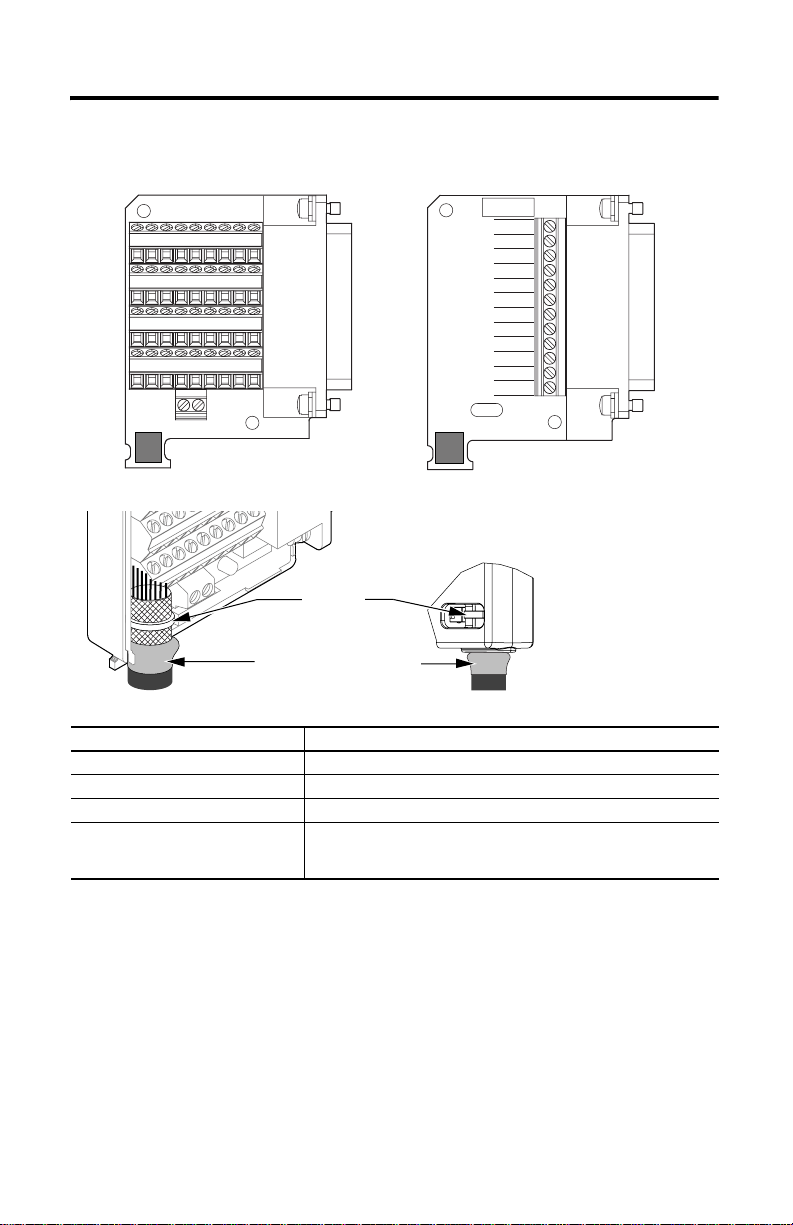
Install the Control Interface Breakout Board
44-pin Breakout Board 12-pin Breakout Board
5V AUX
1X-X+45 6 7 8 9
16 17 18 19 20 21 22 23 24
25 26 27 29 31 32 33 34 35
36 37 38 39 40 41 42 43 44
Follow these steps to form a compact connection.
1. Push the insulation down-and-over itself.
2. Move the insulation so it butts against the outside wall of
cover.
3. Tape or shrink-wrap the end of the insulation to the cable.
Cable Tie
CN1-3
CN1-2
CN1-31
CN1-32
CN1-33
CN1-34
CN1-37
CN1-38
CN1-27
CN1-43
CN1-44
SHIELD
Shrink-wrapped Insulation
Attribute 2090-U3BB2-DM44, 2090-U3BB-DM12
Cable diameter 12.7 mm (0.5 in.) max
2
Screw terminal wire size 0.06…1.31 mm
(30…16 AWG)
Recommended wire strip length 25…63 mm (1.0…2.5 in.)
Recommended torque
Mounting screws
Terminal screws
0.40 N•m (3.5 lb•in)
0.25 N•m (2.2 lb•in)
Rockwell Automation Publication 2090-IN007D-EN-P - August 2010
Page 3

Connector Data
Control Interface Breakout Boards 3
Catalog Number 2090-U3BB2-DM44
1X-X+456789
16 17 18 19 20 21 22 23 24
25 26 27 29 31 32 33 34 35
36 37 38 39 40 41 42 43 44
Shield Terminals
Cable Shield Termination Pad
Terminal Signal Terminal Signal Terminal Signal
1 EPWR_5V 20 IMOUT+ 35 INPUT5
(1)
X–
X+
4 AX+ 23 AOUT 38 INPUT8
5 AX– 24 ILIMIT 39 OUTPUT1
6 BX+ 25 CMND+ 40 OUTPUT2
7 BX– 26 CMND– 41 OUTPUT3
8 IX+ 27 IOCOM 42 OUTPUT4
9 IX– 29 IOPWR 43 RELAY+
16 AMOUT+ 31 INPUT1 44 RELAY–
17 AMOUT– 32 INPUT2 SHIELD
18 BMOUT+ 33 INPUT3 SHIELD
19 BMOUT– 34 INPUT4
(1) The 5.2V DC auxiliary power source is connected to the X+ (positive) and X– (negative) terminals. Do not ground the supply
AUX_COM 21 IMOUT– 36 INPUT6
(1)
5V_AUX_PWR 22 ACOM 37 INPUT7
elsewhere in the system, as X– is connected to the drive chassis ground.
Mounting
Screw (2)
2 x 4-40 UNC
Cover Alignment
Pin (2)
Rockwell Automation Publication 2090-IN007D-EN-P - August 2010
Page 4

Catalog Number 2090-U3BB-DM12
5V AUX
CN1-3
CN1-2
CN1-31
CN1-32
CN1-33
CN1-34
CN1-37
CN1-38
CN1-27
CN1-43
CN1-44
SHIELD
Mounting
Screw (2)
2 x 4-40 UNC
Cover Alignment
Pin (2)
Cable Shield Termination Pad
Connector
Pin
SERCOS Non-SERCOS SERCOS Non-SERCOS
CN1-3 AUXPWR
CN1-2 AUXCOM
Signal Connector
Pin
(1)
(1)
AUXPWR
AUXCOM
(1)
(1)
CN1-37 OTRAV+ INPUT7
CN1-38 OTRAV– INPUT8
Signal
CN1-31 ENABLE INPUT1 CN1-27 I/OCOM I/OCOM
CN1-32 HOME INPUT2 CN1-43 BRAKE+ RELAY+
CN1-33 REG1 INPUT3 CN1-44 BRAKE– RELAY–
CN1-34 REG2 INPUT4 SHIELD SHIELD SHIELD
(1) The 5.2V DC auxiliary power source is connected to the AUXPWR (positive) and AUXCOM (negative) terminals. Do not
ground the supply elsewhere in the system, as AUXCOM is connected to the drive chassis ground.
Allen-Bradley, Rockwell Automation, Rockwell Software, and Ultra3000 are trademarks of Rockwell Automation, Inc.
Tr ademarks not belonging to Rockwell Automation are property of their respective companies.
Rockwell Otomasyon Ticaret A.Ş., Kar Plaza İş Merkezi E Blok Kat:6 34752 İçerenköy, İstanbul, Tel: +90 (216) 5698400
Rockwell Automation Publication 2090-IN007D-EN-P - August 2010 PN-78228
Supersedes Publication 2090-IN007C-EN-P - January 2007 Copyright © 2010 Rockwell Automation, Inc. All rights reserved. Printed in the U.S.A.
 Loading...