

Page 1
Installation Instructions
IMPORTANT
Power with Brake Connector Kit for
TL-Series (Bulletin TLY)
Servo Motors
Catalog Number 2090-KPBM6-16AA
Topic Page
About the TL-Series Power with Brake Connector Kit 1
Important User Information 2
Before You Begin 3
Assemble the Power with Brake Connector Kit 5
Power Connector 6
Additional Resources 7
About the TL-Series Power with Brake Connector Kit
Use this connector kit to build your own power cable, or power with brake cable,
for use with any of these TL-Series servo motors:
This kit is compatible only with power cables from a TLY-A110, TLY-A120, TLY-A130,
TLY-A220, TLY-A230, TLY-A2530, TLY-A2540, or TLY-A310 servo motor.
Page 2
2 Power with Brake Connector Kit for TL-Series Servo Motors Installation Instructions
Important User Information
Solid state equipment has operational characteristics differing from those of electromechanical equipment.
Safety Guidelines for the Application, Installation and Maintenance of Solid State Controls (publication
SGI-1.1
available from your local Rockwell Automation sales office or online at
http://rockwellautomation.com/literature
equipment and hard-wired electromechanical devices. Because of this difference, and also because of the
wide variety of uses for solid state equipment, all persons responsible for applying this equipment must
satisfy themselves that each intended application of this equipment is acceptable.
In no event will Rockwell Automation, Inc. be responsible or liable for indirect or consequential damages
resulting from the use or application of this equipment.
The examples and diagrams in this manual are included solely for illustrative purposes. Because of the many
variables and requirements associated with any particular installation, Rockwell Automation, Inc. cannot
assume responsibility or liability for actual use based on the examples and diagrams.
No patent liability is assumed by Rockwell Automation, Inc. with respect to use of information, circuits,
equipment, or software described in this manual.
Reproduction of the contents of this manual, in whole or in part, without written permission of Rockwell
Automation, Inc., is prohibited.
Throughout this manual, when necessary, we use notes to make you aware of safety considerations.
WARNING: Identifies information about practices or circumstances that can cause an
explosion in a hazardous environment, which may lead to personal injury or death,
property damage, or economic loss.
) describes some important differences between solid state
ATTENTION: Identifies information about practices or circumstances that can lead to
personal injury or death, property damage, or economic loss. Attentions help you
identify a hazard, avoid a hazard and recognize the consequences.
SHOCK HAZARD: Labels may be on or inside the equipment, for example, drive or
motor, to alert people that dangerous voltage may be present.
BURN HAZARD: Labels may be on or inside the equipment, for example, drive or
motor, to alert people that surfaces may reach dangerous temperatures.
IMPORTANT Identifies information that is critical for successful application and understanding of
the product.
Publication 2090-IN018A-EN-P - June 2010
Page 3

Power with Brake Connector Kit for TL-Series Servo Motors Installation Instructions 3
Before You Begin
Identify the wire colors and pinouts specific to your TL-Series (Bulletin TLY) motor by
referring to the Power Connector information on page
ATTENTION: To prevent electrical shock, disconnect the connector, motor, and
drive from the power source before installing or servicing.
This device should be used only in an enclosure that prevents exposure to
contaminants.
ATTENTION: When installing a cable, restrain it so that uneven tension or
flexing at the connector does not occur.
Excessive and uneven force at the cable connector may result in damage to the
housing and contacts as the cable flexes.
Failure to observe this safety procedure could result in damage to the motor
and its components.
You should also refer to the manual for your drive to determine pinouts and wire connections
appropriate to these connections.
TL-Series (Bulletin TLY) motors are compatible with these Allen-Bradley drives:
• Kinetix 300
• Kinetix 2000
• Kinetix 6000
• Kinetix 6200
• Kinetix 6500
• Ultra3000
• Ultra5000
Refer to the Parts List on page
4 for wire sizes compatible with this connector kit.
6.
Publication 2090-IN018A-EN-P - June 2010
Page 4

4 Power with Brake Connector Kit for TL-Series Servo Motors Installation Instructions
IMPORTANT
Parts List
These items are supplied in the connector kit.
Item Qty. Wire Size Insulation
mm² (AWG) mm (in.) mm (in.)
Power sockets 8 0.8…1.4
Brake sockets 15 66505-9
Housing 1 N/A 205839-3
(1)
Backshell
(1) The maximum cable diameter, including wiring and jacket material, allowed by this backshell is 11.51 mm (0.45 in.),
(18…16)
1 N/A 206070-8
Diameter
2.54 (0.10) max 2.5 (0.1) 66101-4
Insulation
Strip Length
Tyco AMP Part No.
Tool List
Use these tools to assemble the connector kit.
Tools are not provided in the connector kit.
Required Tools
Item Tyco AMP Part No.
Hand crimp tool - power contacts 58495-1
Extraction tool - power contact 305183
Extraction tool - ground contact 725840-1
Insertion tool - power, brake, and ground contacts 91002-1
Wire cutter N/A
Wire stripper
Screwdriver, size 0 or 1 Phillips
Needle-nose pliers (optional)
Publication 2090-IN018A-EN-P - June 2010
Page 5

Power with Brake Connector Kit for TL-Series Servo Motors Installation Instructions 5
IMPORTANT
Assemble the Power with Brake Connector Kit
Follow these steps to assemble your TL-Series (Bulletin TLY) connector kit.
ATTENTION: To prevent electrical shock, disconnect the connector, motor, and
drive from the power source before installing or servicing.
This device should be used only in an enclosure that prevents exposure to
contaminants.
1. Slide the backshell onto the cable.
2. Remove the insulation from the end of the wires to expose a maximum of
2.5 mm (0.1 in.) of wire.
3. Crimp a socket on each wire.
4. Refer to the Parts List
Power Connector
position for each wire.
5. Insert the socket of each wire into the appropriate position at the back of the
connector housing.
6. Ground the cable shield.
7. Screw the backshell onto the connector housing.
8. Select the type of backshell clamp, and determine its appropriate
orientation.
The type and orientation of the backshell clamp is dependent on your application.
9. Tighten the backshell clamp screws until the backshell clamp applies
sufficient pressure on the cable jacket to retain the cable.
on page 4 for the correct socket type. Refer to the
table on page 6 for the correct wire and connector
Do not over-tighten the backshell clamp screws.
Applying excessive force may damage the threads in the plastic backshell.
Publication 2090-IN018A-EN-P - June 2010
Page 6
6 Power with Brake Connector Kit for TL-Series Servo Motors Installation Instructions
3
6
9
1
4
7
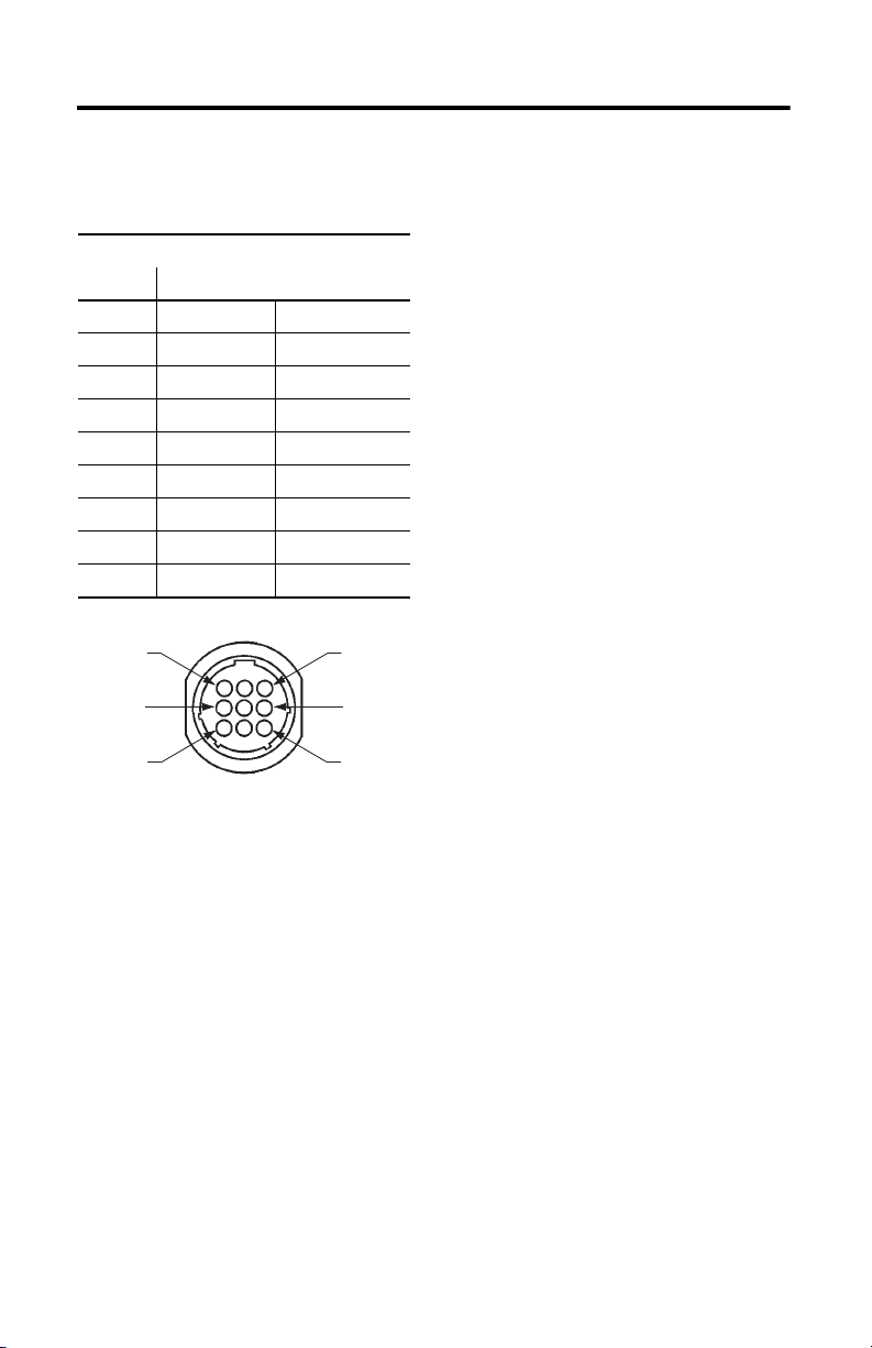
Front of Tyco AMP 206705-2 Housing
Power Connector
This table shows the pin connections for the power connector on a TL-Series motor.
Motor Power Connections
(2)
Pin Signal Wire Color
1 U Phase Red
2 V Phase Black
3 W Phase White
4 Reserved —
5 Ground Green/Yellow
6 Reserved —
(1)
7 MBRK+
8 Reserved —
9 MBRK-
Power Cable Pinouts
(1)
Yellow
Blue
(1) Brake pins are to be used only with brake motors, catalog numbers TLY-A/Bxxxx-xxx4xx.
(2) The wire is internal to the TL-Series motor. For consistency, wires of the same color should be used in any cable.
Publication 2090-IN018A-EN-P - June 2010
Page 7

Power with Brake Connector Kit for TL-Series Servo Motors Installation Instructions 7
Additional Resources
These documents contain additional information about related Rockwell Automation products.
Resource Description
Kinetix 300 Single-axis Servo Drives User
Manual, publication 2097-UM001
Kinetix 2000 Multi-axis Servo Drives User
Manual, publication 2093-UM001
Kinetix 6000 Multi-axis Servo Drives User
Manual, publication 2094-UM001
Kinetix 6200 and Kinetix 6500 Modular
Multi-axis Servo Drives User Manual,
publication 2094-UM002
Ultra3000 Digital Servo Drive Installation
Manual, publication 2098-IN003
Ultra3000 Digital Servo Drive Integration
Manual, publication 2098-IN005
Ultra5000 Intelligent Positioning Drives
Installation Manual, publication 2098-IN001
Allen-Bradley Industrial Automation Glossary,
publication AG-7.1
System Design for Control of Electrical Noise
Reference Manual, publication GMC-RM001
Kinetix Motion Control Selection Guide,
publication GMC-SG001
How to install, set up, and troubleshoot a servo-drive
system.
A glossary of industrial automation terms and
abbreviations.
Information, examples, and techniques designed to
minimize system failures caused by electrical noise.
Specifications, motor/servo-drive system combinations,
and accessories for Kinetix motion control products.
You can view or download publications at
http://rockwellautomation.com/literature. To order paper copies of technical
documentation, contact your local Rockwell Automation distributor or sales
representative.
Publication 2090-IN018A-EN-P - June 2010
Page 8

Rockwell Automation Support
Rockwell Automation provides technical information on the Web to assist you in using its products. At
http://www.rockwellautomation.com/support/
technical and application notes, sample code and links to software service packs, and a MySupport feature that
you can customize to make the best use of these tools.
For an additional level of technical phone support for installation, configuration and troubleshooting, we offer
TechConnect support programs. For more information, contact your local distributor or Rockwell Automation
representative, or visit http://www.rockwellautomation.com/support/
Installation Assistance
If you experience a problem within the first 24 hours of installation, please review the information that's
contained in this manual. You can also contact a special Customer Support number for initial help in getting your
product up and running.
United States or Canada 1.440.646.3434
Outside United States
or Canada
Use the Worldwide Locator
http://www.rockwellautomation.com/support/americas/phone_en.html
your local Rockwell Automation representative.
New Product Satisfaction Return
Rockwell Automation tests all of its products to ensure that they are fully operational when shipped from the
manufacturing facility. However, if your product is not functioning and needs to be returned, follow these
procedures.
, you can find technical manuals, a knowledge base of FAQs,
.
at
, or contact
United States
Outside United States
Contact your distributor. You must provide a Customer Support case number (call the
phone number above to obtain one) to your distributor to complete the return process.
Please contact your local Rockwell Automation representative for the return
procedure.
Documentation Feedback
Your comments will help us serve your documentation needs better. If you have any suggestions on how to
improve this document, complete this form, publication RA-DU002
http://www.rockwellautomation.com/literature/
Allen-Bradley, Kinetix, Rockwell Automation, Rockwell Software, TechConnect, TL-Series, Ultra3000, and Ultra5000 are
trademarks of Rockwell Automation, Inc.
Trademarks not belonging to Rockwell Automation are property of their respective companies.
Rockwell Otomasyon Ticaret A.Ş., Kar Plaza İş Merkezi E Blok Kat:6 34752 İçerenköy, İstanbul, Tel : +90 (216) 5698400
.
Publication 2090-IN018A-EN-P - June 2010 PN-17270
, available at
Copyright © 2010 Rockwell Automation, Inc. All rights reserved. Printed in the U.S.A.
 Loading...