

Page 1
Installation Instructions
Continuous-flex Feedback Cables
with SpeedTec DIN Connector
Catalog Numbers 2090-CFBM7DD-CEAFxx, 2090-CFBM7DF-CDAFxx,
2090-CFBM7DF-CEAFxx, 2090-CFBM7E7-CDAFxx, 2090-CFBM7E7-CEAFxx
Topic Page
About Continuous-flex Feedback Cables 1
Important User Information 2
Before You Begin 3
Install Cables 4
Schematics and Connector Pinouts for Cables 6
Specifications 11
Additional Resources 12
About Continuous-flex Feedback Cables
Continuous-flex feedback cables can be repeatedly flexed within a specified bend radius when
properly installed. A circular SpeedTec-ready receptacle and/or a SpeedTec plug is attached to
the cable.
Page 2
2 Continuous-flex Feedback Cables with SpeedTec DIN Connector
Important User Information
Solid state equipment has operational characteristics differing from those of electromechanical equipment.
Safety Guidelines for the Application, Installation and Maintenance of Solid State Controls, publication
, is available from your local Rockwell Automation sales office or online at
SGI-1.1
http://www.rockwellautomation.com/literature
equipment and hard-wired electromechanical devices. Because of this difference, and also because of the
wide variety of uses for solid state equipment, all persons responsible for applying this equipment must
satisfy themselves that each intended application of this equipment is acceptable.
In no event will Rockwell Automation, Inc. be responsible or liable for indirect or consequential damages
resulting from the use or application of this equipment.
The examples and diagrams in this manual are included solely for illustrative purposes. Because of the many
variables and requirements associated with any particular installation, Rockwell Automation, Inc. cannot
assume responsibility or liability for actual use based on the examples and diagrams.
No patent liability is assumed by Rockwell Automation, Inc. with respect to use of information, circuits,
equipment, or software described in this manual.
Reproduction of the contents of this manual, in whole or in part, without written permission of Rockwell
Automation, Inc., is prohibited.
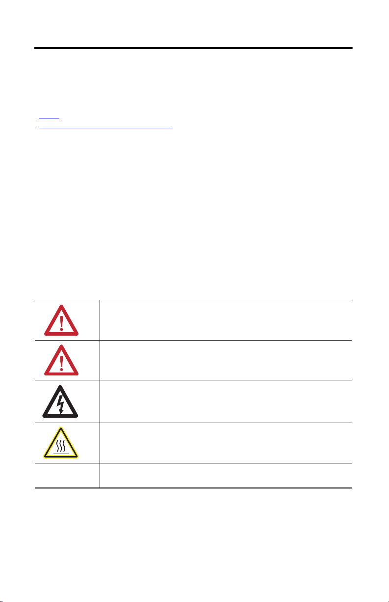
Throughout this manual, when necessary, we use notes to make you aware of safety considerations.
WARNING: Identifies information about practices or circumstances that can cause an
explosion in a hazardous environment, which may lead to personal injury or death,
property damage, or economic loss.
) describes some important differences between solid state
ATTENTION: Identifies information about practices or circumstances that can lead to
personal injury or death, property damage, or economic loss. Attentions help you
identify a hazard, avoid a hazard and recognize the consequences.
SHOCK HAZARD: Labels may be on or inside the equipment, for example, drive or
motor, to alert people that dangerous voltage may be present.
BURN HAZARD: Labels may be on or inside the equipment, for example, drive or
motor, to alert people that surfaces may reach dangerous temperatures.
IMPORTANT Identifies information that is critical for successful application and understanding of
the product.
Publication 2090-IN027B-EN-P - January 2011
Page 3
Continuous-flex Feedback Cables with SpeedTec DIN Connector 3
IMPORTANT
Before You Begin
Remove all packing material from within and around the item. After unpacking, verify the
catalog number against the purchase order, and visually inspect the cable and each connector for
damage. If necessary, notify the carrier of any shipping damage immediately.
Cables are stored and shipped in a coil, and will retain this shape unless you allow the cable to
straighten itself. To straighten a cable, hang a short cable from its mid-point or lay a long cable on
the floor in a straight line. Any coiling that persists in the cable should relax within the next
24 hours. Doing this results in a cable that is easier to install.
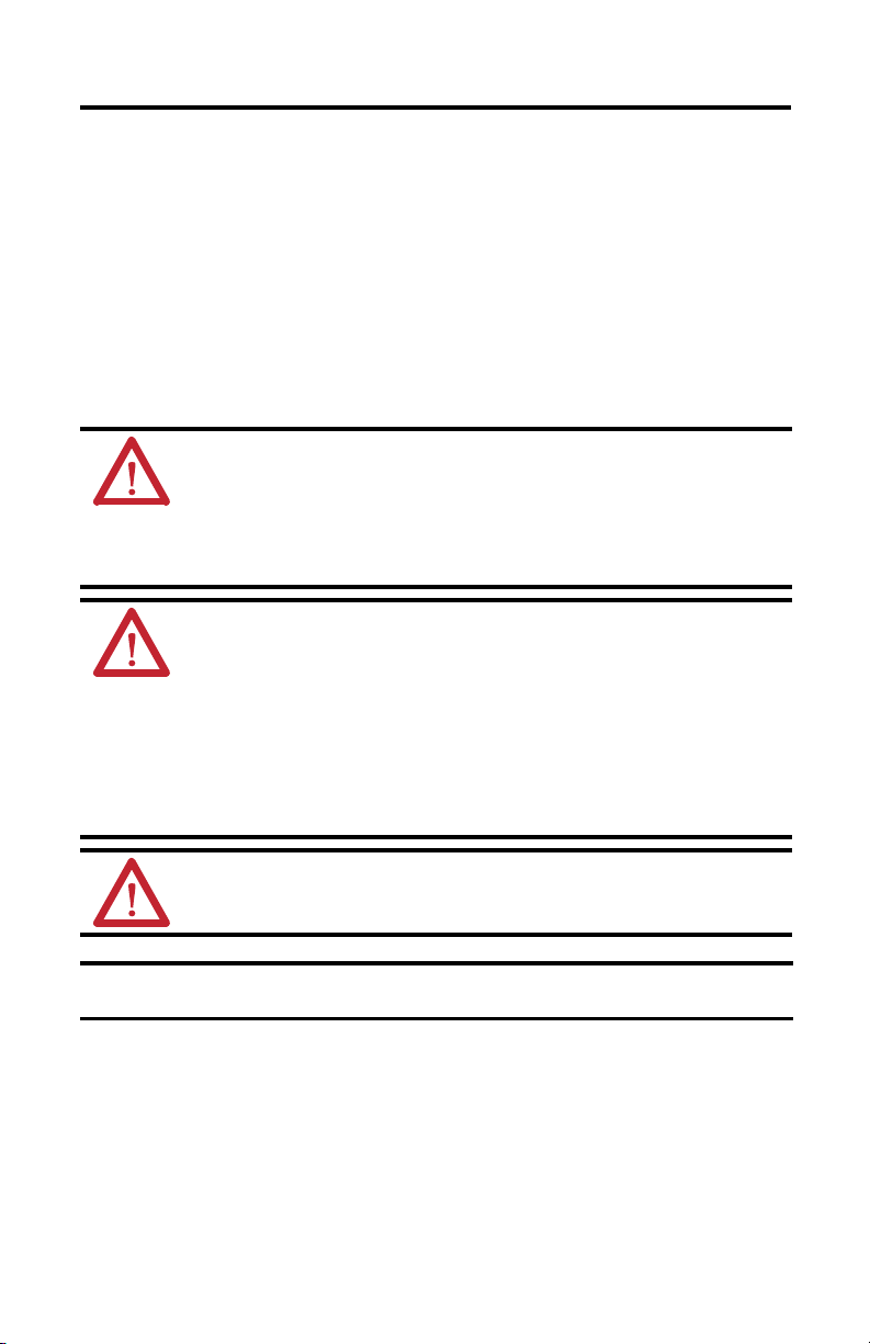
Observe the following precautions when installing the cables in a servo system. Failure to observe
these safety notices could result in personal injury or damage to the motor and equipment.
ATTENTION: Arcing or unexpected motion can occur if the power, brake, or
feedback cables are connected or disconnected while power is applied to the drive.
Always remove power to the servo drive before connecting or disconnecting cables
at the drive or at the motor.
Failure to observe these safety procedures could result in personal injury or
damage to the motor and equipment.
ATTENTION: The examples in this publication show the available connections,
some of which may not be appropriate for your specific installation. Refer to your
drive installation instructions or user manual for recommended wire trim lengths,
and wiring examples appropriate to your drive and motor application.
Do not connect unused wires. Unused wires may be trimmed and finished as
necessary to prevent accidental contact with other wires or wire shields, or with a
ground connection.
Failure to observe these safety procedures could result in personal injury or
damage to the motor and equipment.
ATTENTION: The maximum length of cabling between the drive and the motor
must not exceed 90 m (295.5 ft). Also, a maximum of two extension cables may be
connected from a motor to a drive.
Continuous-flex cables with SpeedTec connectors are incompatible with some
MP-Series motors.
Publication 2090-IN027B-EN-P - January 2011
Page 4
4 Continuous-flex Feedback Cables with SpeedTec DIN Connector
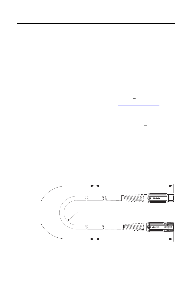
Flex Area
Dynamic and continuous
flexing permitted to the
operational bend radius.
2090-CFBM7E7-CEAFxx Shown
Installation Area
300 mm (12 in.) approx.
Bend Radius
Refer to Specifications
on
page 11 for the specific value.
Installation Area
300 mm (12 in.) approx.
Install Cables
Follow these steps when installing a cable.
1. Provide the recommended installation areas, and the correct offset from features, before
beginning any cable bend.
Features include these areas on the cable:
• Connectors
• Transitions from exposed wire to insulation (for example, flying leads)
• Exposed cable ground shields
The offset from these areas should be greater than or equal to (>
2. Keep cable bends within the bend radius listed in the Specifications
General guidelines for the bend radius of a cable are listed below, however, individual
cables may have additional restrictions:
• Standard cables have a static or one-time bend radius of 10 times (<10x) the cable
diameter.
• Continuous-flex cables have an operational bend radius of 12 times (<12x) the cable
diameter.
3. Observe these restrictions on the flex zone and installation areas when installing the
cable:
• The flex zone is the area in which the cable can flex many times without breakage.
• Installation areas require rigid mounting to prevent the cable from flexing where it
connects to other components.
1x) the cable diameter.
on page 11.
Publication 2090-IN027B-EN-P - January 2011
Page 5

Continuous-flex Feedback Cables with SpeedTec DIN Connector 5
IMPORTANT
SpeedTec Plug
Threaded Plug
Remove O-ring when mating with a
SpeedTec plug.
Install O-ring when mating with a
threaded plug.
O-ring in Groove
If an O-ring is installed, a SpeedTec plug will not engage with the receptacle.
4. Identify each connection on a cable with flying leads by attaching a label around the
outer insulation of each wire adjacent to the drive connection or connector kit terminals.
5. Remove the O-ring on the motor connector when using a feedback cable with a
SpeedTec feedback plug.
The type of plug on the feedback cable determines whether an O-ring is required on the
feedback receptacle. These cables have a SpeedTec feedback plug and do not require the
O-ring:
• 2090-CFBM7DD-CEAFxx
• 2090-CFBM7DF-CDAFxx
• 2090-CFBM7DF-CEAFxx
• 2090-CFBM7E7-CDAFxx
• 2090-CFBM7E7-CEAFxx
The O-ring dampens the effects of vibration at the cable-to-motor connection.
This creates a more secure connection for a cable with a threaded plug.
Publication 2090-IN027B-EN-P - January 2011
Page 6

6 Continuous-flex Feedback Cables with SpeedTec DIN Connector
Twisted Wire Pair
Connector Backshell Shielded 360°
Wire Connection
Shield
To
Motor
To
Drive
Schematics and Connector Pinouts for Cables
Wire colors and connector pinouts necessary to connect the cable to a servo system are shown in
the schematics.
2090-CFBM7DD-CEAFxx Cable
This cable is available in several cable lengths with a D-sub connector on the drive-end of the
cable. Refer to the Kinetix Motion Control Selection Guide, publication GMC-SG001
information and additional specifications.
, for this
1
2
3
4
5
6
9
10
11
13
14
12
2
13
3
4
5
SIN+/AM+
SIN-/AM-
COS+/BM+
COS-/BMDATA+/IM+/R1
DATA-/IM-/R2
EPWR 5V
ECOM
EPWR 9V
TS+
TSECOM
1
11
12
10
16
9
1514
8
17
7
6
22 AWG Black
22 AWG White/Black
22 AWG Red
22 AWG White/Red
22 AWG Green
22 AWG White/Green
22 AWG Gray
22 AWG White/Gray
22 AWG Orange
22 AWG White/Orange
10
5
1
SIN+/AM+
SIN-/AM-
COS+/BM+
COS-/BM-
DATA+/IM+
DATA-/IM-
EPWR 5V
ECOM
EPWR 9V
TS+
15
11
6
1
2
3
4
5
10
14
6
7
11
Publication 2090-IN027B-EN-P - January 2011
Page 7

Continuous-flex Feedback Cables with SpeedTec DIN Connector 7
Twisted Wire Pair
To
Motor
Connector Backshell Shielded 360°
Wire Connection
To
Drive
Shield
Connect Cable Shield to Ground
2090-CFBM7DF-CDAFxx Cable
This cable is available in several lengths with flying leads for connection to a drive. Refer to the
Kinetix Motion Control Selection Guide, publication GMC-SG001
additional specifications.
1
11
2
12
10
13
3
16
9
1514
8
17
4
7
5
6
, for this information and
SIN+/AM+
1
SIN-/AM-
2
COS+/BM+
3
COS-/BM-
4
DATA+/IM+
5
DATA-/IM-
6
EPWR 5V
9
ECOM
10
EPWR 9V
11
TS+
13
TS-
14
S1
15
S2
16
S3
17
Spare
7
ABS
8
ECOM
12
N/C
26 AWG Black
26 AWG White/Black
26 AWG Red
26 AWG White/Red
26 AWG Green
26 AWG White/Green
16 AWG Gray
16 AWG White/Gray
22 AWG Orange
22 AWG White/Orange
26 AWG Blue
26 AWG White/Blue
26 AWG Yellow
26 AWG White/Yellow
26 AWG Brown
26 AWG White/Brown
36 AWG Shield
N/C
N/C
SIN+/AM+
SIN-/AM-
COS+/BM+
COS-/BM-
DATA+/IM+
DATA-/IM-
EPWR 5V
EPWR 9V
ECOM
TS+
S1
S2
S3
Spare
ABS
Publication 2090-IN027B-EN-P - January 2011
Page 8

8 Continuous-flex Feedback Cables with SpeedTec DIN Connector
1
2
3
4
5
10
14
6
7
11
22 AWG Black
22 AWG White/Black
22 AWG Red
22 AWG White/Red
22 AWG Green
22 AWG White/Green
22 AWG Gray
22 AWG White/Gray
22 AWG Orange
22 AWG White/Orange
1
2
3
4
5
6
9
10
11
13
14
12
SIN+/AM+
SIN-/AM-
COS+/BM+
COS-/BMDATA+/IM+/R1
DATA-/IM-/R2
EPWR 5V
ECOM
EPWR 9V
TS+
TSECOM
SIN+/AM+
SIN-/AM-
COS+/BM+
COS-/BM-
DATA+/IM+
DATA-/IM-
EPWR 5V
ECOM
EPWR 9V
TS+
1
2
3
4
5
16
1514
13
12
11
10
9
8
7
6
17
Twisted Wire Pair
Connector Backshell Shielded 360°
Wire Connection
Shield
Connect Cable Shield to Ground
To
Motor
To
Drive
2090-CFBM7DF-CEAFxx Cable
This cable is available in several cable lengths with flying leads for connection to a drive. Refer to
the Kinetix Motion Control Selection Guide, publication GMC-SG001
and additional specifications.
, for this information
Publication 2090-IN027B-EN-P - January 2011
Page 9

Continuous-flex Feedback Cables with SpeedTec DIN Connector 9
1
2
3
4
5
10
14
6
7
11
22 AWG Black
22 AWG White/Black
22 AWG Red
22 AWG White/Red
22 AWG Green
22 AWG White/Green
22 AWG Gray
22 AWG White/Gray
22 AWG Orange
22 AWG White/Orange
1
2
3
4
5
6
9
10
11
13
14
12
SIN+/AM+
SIN-/AM-
COS+/BM+
COS-/BMDATA+/IM+/R1
DATA-/IM-/R2
EPWR 5V
ECOM
EPWR 9V
TS+
TSECOM
SIN+/AM+
SIN-/AM-
COS+/BM+
COS-/BM-
DATA+/IM+
DATA-/IM-
EPWR 5V
ECOM
EPWR 9V
TS+
1
2
3
4
5
16
1514
13
12
11
10
9
8
7
6
17
Twisted Wire Pair
Wire Connection
Shield
To
Motor
To
Drive
Connector Backshell Shielded 360°
Connect Cable Shield to Ground
2090-CFBM7E7-CDAFxx Cable
This extension cable is available in several lengths and with circular SpeedTec connectors on
both ends of the cable. Refer to the Kinetix Motion Control Selection Guide, publication
GMC-SG001
, for this information and additional specifications.
Publication 2090-IN027B-EN-P - January 2011
Page 10

10 Continuous-flex Feedback Cables with SpeedTec DIN Connector
1
2
3
4
5
10
14
6
7
11
22 AWG Black
22 AWG White/Black
22 AWG Red
22 AWG White/Red
22 AWG Green
22 AWG White/Green
22 AWG Gray
22 AWG White/Gray
22 AWG Orange
22 AWG White/Orange
1
2
3
4
5
6
9
10
11
13
14
12
SIN+/AM+
SIN-/AM-
COS+/BM+
COS-/BMDATA+/IM+/R1
DATA-/IM-/R2
EPWR 5V
ECOM
EPWR 9V
TS+
TSECOM
SIN+/AM+
SIN-/AM-
COS+/BM+
COS-/BM-
DATA+/IM+
DATA-/IM-
EPWR 5V
ECOM
EPWR 9V
TS+
1
2
3
4
5
16
1514
13
12
11
10
9
8
7
6
17
1
2
3
4
5
16
15
14
13
12
11
10
9
8
7
6
17
Twisted Wire Pair
Connector Backshell Shielded 360°
Wire Connection
Shield
To
Motor
To
Drive
2090-CFBM7E7-CEAFxx Cable
This extension cable is available in several lengths and with circular SpeedTec connectors on
both ends of the cable. Refer to the Kinetix Motion Control Selection Guide, publication
GMC-SG001
, for this information and additional specifications.
Publication 2090-IN027B-EN-P - January 2011
Page 11

Continuous-flex Feedback Cables with SpeedTec DIN Connector 11
Specifications
These specifications provide information that is useful when installing a cable. Additional
specifications for each cable are available in the Kinetix Motion Control Selection Guide,
publication GMC-SG001
2090-CFBM7DF-CDAFxx and 2090-CFBM7E7-CDAFxx Cables
.
Attribute
Diameter 12.0 mm (0.5 in.)
(1)
Bend radius
Flex area 140 mm (5.5 in.)
Installation areas
(1) Apply the bend radius multiplier for operational (12 x dia.) and static (10 x dia.) bend radius to cables with a different
diameter. Refer to the diagram to locate the areas for flex (operational) and static (installation) bend areas.
(2) The installation areas are approximately 300 mm (12 in.) in length at both ends of the cable. Secure this area with a rigid
mount that prevents the cable from flexing where it connects to other components.
(2)
2090-CFBM7xx-CDAFxx
120 mm (5.0 in.)
2090-CFBM7DD-CEAFxx, 2090-CFBM7DF-CEAFxx, and 2090-CFBM7E7-CEAFxx Cables
Attribute
Diameter 10.0 mm (0.395 in.)
Bend radius
(1) Apply the bend radius multiplier for operational (12 x dia.) and static (10 x dia.) bend radius to cables with a different
(2) The installation areas are approximately 300 mm (12 in.) in length at both ends of the cable. Secure this area with a rigid
(1)
Flex area 120 mm (5.0 in.)
(2)
Installation areas
diameter. Refer to the diagram to locate the areas for flex (operational) and static (installation) bend areas.
mount that prevents the cable from flexing where it connects to other components.
2090-CFBM7xx-CEAFxx
100 mm (4.0 in.)
Publication 2090-IN027B-EN-P - January 2011
Page 12

Additional Resources
These documents contain additional information concerning related Rockwell Automation
products.
Resource Description
Kinetix 300 EtherNet/IP Indexing Servo Drives
User Manual, publication 2097-UM001
Kinetix 2000 Multi-axis Servo Drive User
Manual, publication 2093-UM001
Kinetix 6000 Multi-axis Servo Drives User
Manual, publication 2094-UM001
Kinetix 6200 and Kinetix 6500 Modular
Multi-axis Servo Drives User Manual,
publication 2094-UM002
Kinetix 7000 High Power Servo Drive User
Manual, publication 2099-UM001
Ultra3000 Digital Servo Drive Installation
Manual, publication 2098-IN003
Manual, publication 2098-IN005
Ultra5000 Intelligent Positioning Drives
Installation Manual, publication 2098-IN00
Allen-Bradley Industrial Automation Glossary,
publication AG-7.1
System Design for Control of Electrical Noise
Reference Manual, publication GMC-RM001
Kinetix Motion Control Selection Guide,
publication GMC-SG001
Rockwell Automation Product Certification
website
http://www.rockwellautomation.com/products/
certification/
or Integration
How to install, set up, and troubleshoot a servo-drive
system.
1
A glossary of industrial automation terms and
abbreviations.
Information, examples, and techniques designed to
minimize system failures caused by electrical noise.
Specifications, motor/servo-drive system combinations,
and accessories for Kinetix motion control products.
Declarations of Conformity (DOC) for Rockwell Automation
products.
You can view or download publications at http://www.rockwellautomation.com/literature
.
To order paper copies of technical documentation, contact your local Rockwell Automation
distributor or sales representative.
Allen-Bradley, Kinetix, MP-Series, Rockwell Automation, Rockwell Software, Ultra3000, and Ultra5000 are trademarks of Rockwell
Automation, Inc.
Trademarks not belonging to Rockwell Automation are property of their respective companies.
Rockwell Otomasyon Ticaret A.Ş., Kar Plaza İş Merkezi E Blok Kat:6 34752 İçerenköy, İstanbul, Tel: +90 (216) 5698400
Publication 2090-IN027B-EN-P January 2011 PN-95742
Supersedes Publication 2090-IN027A-EN-P October 2009 Copyright © 2011 Rockwell Automation, Inc. All rights reserved. Printed in the U.S.A.
 Loading...